Page 105 of 255
5Carefully remove the diaphragm and
operating rod assembly from the housing.
Examine the diaphragm for signs of splits or
holes and renew if necessary.
6Ensure that the diaphragm housing and
cover mating surfaces are clean, then insert
the diaphragm into the housing, aligning the
hole in the diaphragm with the housing
vacuum gallery.
7Ensure that the diaphragm is not kinked or
distorted in any way then locate the spring in
diaphragm centre. Refit the cover, aligning the
cover port with the housing gallery, and
securely tighten the retaining screws.
8Reconnect the operating rod to the throttle
linkage, then refit the air cleaner and
reconnect the battery negative terminal.
1Disconnect the battery negative terminal.
2For improved access, remove the air cleaner.
3Thoroughly clean all external dirt from
around the power valve housing.
4Remove the three retaining screws then lift off
the power valve cover and remove the spring.5Withdraw the diaphragm from the housing
flange. Inspect the diaphragm for cracks or
holes and renew if necessary.
6Ensure that the diaphragm and housing
flange mating surfaces are clean then insert
the diaphragm into the housing, aligning the
hole in the diaphragm with the corresponding
hole in the housing flange.
7Ensure that the diaphragm is not kinked or
distorted in any way, then locate the spring in
diaphragm centre. Refit the cover and tighten
the retaining screws securely.
8Refit the air cleaner and reconnect the
battery.
1This procedure is as describedfor the
power valve. Note the following points.
a)If necessary disconnect the vacuum pipe
from the diaphragm cover, and ensure it is
securely reconnected on completion.
b)The diaphragm cover is retained by four
screws.1This procedure is as described for the
power valve. Note the following points.
a)The accelerator pump cover is secured by
four screws.
b)The diaphragm return spring is fitted
between the pump housing and the
diaphragm, not between the diaphragm
and the cover.
c)When removing the return spring, the
supply valve should come out on the end
of the spring, complete with the O-ring
seal. Check the valve and the O-ring for
damage, and renew them if necessary.
When refitting, ensure that the O-ring seal
is correctly fitted to the end of the valve.
1Remove the carburettor top cover.
2Note the position of the alignment marks on
the choke housing and bi-metal housing and,
if necessary, make additional alignment marks
to aid refitting. Remove the three screws and
lift off the bi-metal housing and retaining plate.
3Remove the internal heat shield.
4Remove the three choke housing screws,
noting that it may be necessary to disconnect
the fast idle cam return spring to access one
of the screws, then disconnect the choke link
from the operating lever and remove the
automatic choke unit. Recover the O-ring from
the rear of the unit.
5 Undo the three retaining screws then
remove the vacuum pulldown diaphragm
cover and withdraw the diaphragm. Examine
the diaphragm for signs of splits or holes and
renew if necessary.
26Weber 2V TLD carburettor -
automatic choke unit removal,
refitting and adjustment
25Weber 2V TLD carburettor -
accelerator pump diaphragm
renewal
24Weber 2V TLD carburettor -
low vacuum enrichment
diaphragm renewal
23Weber 2V TLD carburettor -
power valve diaphragm renewal
4•12Fuel and exhaust systems
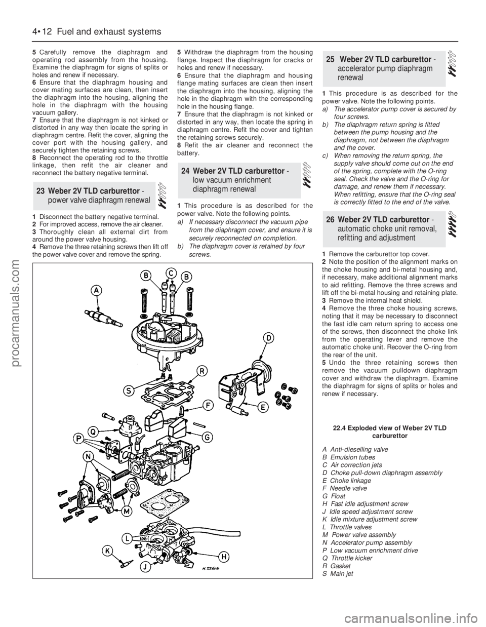
A Anti-dieselling valve
B Emulsion tubes
C Air correction jets
D Choke pull-down diaphragm assembly
E Choke linkage
F Needle valve
G Float
H Fast idle adjustment screw
J Idle speed adjustment screw
K Idle mixture adjustment screw
L Throttle valves
M Power valve assembly
N Accelerator pump assembly
P Low vacuum enrichment drive
Q Throttle kicker
R Gasket
S Main jet
22.4 Exploded view of Weber 2V TLD
carburettor
procarmanuals.com
Page 106 of 255
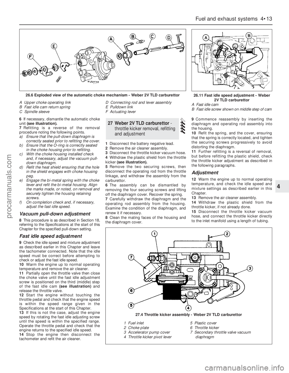
6If necessary, dismantle the automatic choke
unit (see illustration).
7Refitting is a reverse of the removal
procedure noting the following points.
a)Ensure that the pull-down diaphragm is
correctly seated prior to refitting the cover.
b)Ensure that the O-ring is correctly seated
in the choke housing prior to refitting.
c)With the choke housing installed check
and, if necessary, adjust the vacuum pull-
down diaphragm.
d)Refit the heat shield ensuring that the hole
in the shield engages with choke housing
peg.
e)Engage the bi-metal spring with the choke
lever and refit the bi-metal housing. Align
the marks made, or noted, on removal and
securely tighten the housing retaining
screws.
f)On completion check and, if necessary,
adjust the fast idle speed.
Vacuum pull-down adjustment
8This procedure is as described in Section 18,
referring to the Specifications at the start of this
Chapter for the specified pull-down setting.
Fast idle speed adjustment
9Check the idle speed and mixture adjustment
as described earlier in this Chapter and leave
the tachometer connected. Note that the idle
speed must be correct before attempting to
check or adjust the fast idle speed.
10Warm the engine up to normal operating
temperature and remove the air cleaner.
11Partially open the throttle valve then close
the choke valve until the fast idle adjustment
screw is positioned on the third (middle) step
of the fast idle cam(see illustration)and
release the throttle valve.
12Start the engine without touching the
throttle pedal and check that the engine speed
is within the speed range given in the
Specifications at the start of this Chapter.
13If this is not the case, adjust the engine
speed by rotating the fast idle adjusting screw
until the speed is within the specified range.
Operate the throttle pedal and check that the
engine returns to the specified idle speed.
14Stop the engine then disconnect the
tachometer and refit the air cleaner.1Disconnect the battery negative lead.
2Remove the air cleaner assembly.
3Disconnect the throttle kicker vacuum hose.
4Withdraw the plastic shield from the throttle
kicker(see illustration).
5Remove the two securing screws, then
disconnect the operating rod from the throttle
linkage, and withdraw the assembly from the
carburettor.
6The assembly can be dismantled by
removing the four securing screws and lifting
off the diaphragm cover. Recover the spring.
7Carefully withdraw the diaphragm and the
operating rod assembly from the housing.
Examine the condition of the diaphragm, and
renew it if necessary.
8Clean the mating faces of the housing and
the diaphragm cover.9Commence reassembly by inserting the
diaphragm and operating rod assembly into
the housing.
10Refit the spring, and the cover, ensuring
that the spring is correctly located, and tighten
the securing screws progressively to avoid
distorting the diaphragm.
11Further refitting is a reversal of removal,
but before refitting the plastic shield, check
the throttle kicker adjustment as described in
the following paragraphs.
Adjustment
12Warm the engine up to normal operating
temperature, and check the idle speed and
mixture settings as described earlier in this
Chapter.
13Remove the air cleaner assembly.
14Withdraw the plastic shield from the
throttle kicker, if not already done.
15Disconnect the throttle kicker vacuum
hose, and connect the throttle kicker directly
to the inlet manifold using a length of tubing.
27Weber 2V TLD carburettor -
throttle kicker removal, refitting
and adjustment
Fuel and exhaust systems 4•13
4
26.11 Fast idle speed adjustment - Weber
2V TLD carburettor
A Fast idle cam
B Fast idle screw shown on middle step of cam26.6 Exploded view of the automatic choke mechanism - Weber 2V TLD carburettor
A Upper choke operating link
B Fast idle cam return spring
C Spindle sleeveD Connecting rod and lever assembly
E Pulldown link
F Actuating lever
27.4 Throttle kicker assembly - Weber 2V TLD carburettor
1 Fuel inlet
2 Choke plate
3 Accelerator pump cover
4 Throttle kicker pivot lever5 Plastic cover
6 Throttle kicker
7 Secondary throttle valve vacuum
diaphragm
procarmanuals.com
Page 107 of 255
16Start the engine and note the engine
speed (rpm). The engine speed should
increase above the normal idle speed, and
should be as given in the Specifications.
17If the engine speed is not as specified,
remove the tamperproof plug from the top of
the throttle kicker housing, and turn the
adjustment screw to give the specified speed.
18On completion of adjustment, fit a new
tamperproof cap.
19Disconnect the tubing from the inlet
manifold, and reconnect the throttle kicker
vacuum hose.
20Refit the plastic shield and the air cleaner.
On 2.4 & 2.9 litre V6 models especially,
residual pressure will remain in the fuel lines
long after the vehicle was last used therefore
the fuel system must be depressurised before
any hose is disconnected; the system is
depressurised via the vent valve on the fuel
rail, noting that it may be necessary to depress
the valve several times before the pressure is
fully released. As an added precaution place a
rag over the valve as it is depressed to catch
any fuel which is forcibly expelled. Before
carrying out any operation on the fuel system
refer to the precautions given in Safety first! at
the beginning of this Manual and follow them
implicitly. Petrol is a highly dangerous and
volatile liquid and the precautions necessary
when handling it cannot be overstressed.
Access to the relays is obtained by
removing the facia top cover (crash pad).
The relays are located on the passenger
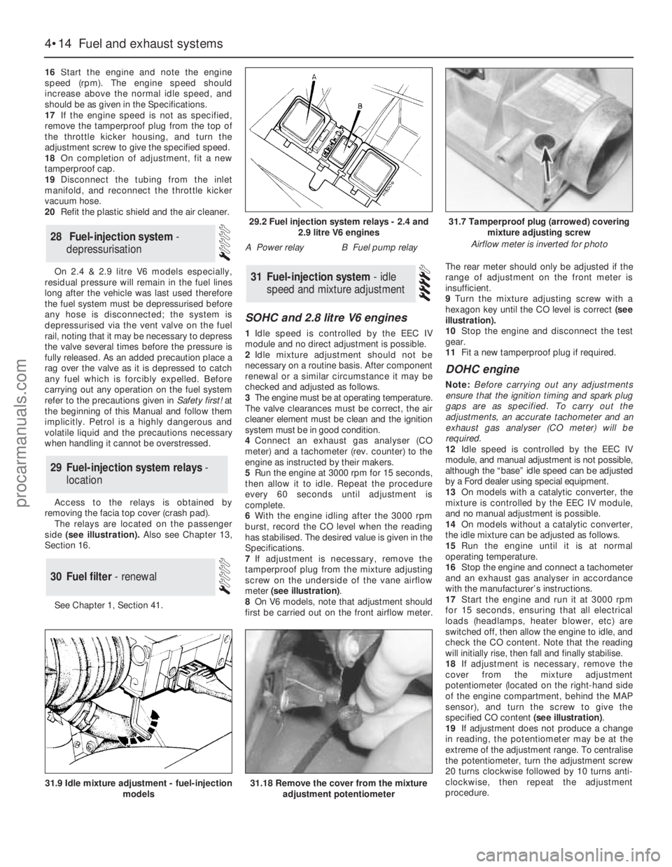
side(see illustration). Also see Chapter 13,
Section 16.
See Chapter 1, Section 41.
SOHC and 2.8 litre V6 engines
1Idle speed is controlled by the EEC IV
module and no direct adjustment is possible.
2Idle mixture adjustment should not be
necessary on a routine basis. After component
renewal or a similar circumstance it may be
checked and adjusted as follows.
3The engine must be at operating temperature.
The valve clearances must be correct, the air
cleaner element must be clean and the ignition
system must be in good condition.
4Connect an exhaust gas analyser (CO
meter) and a tachometer (rev. counter) to the
engine as instructed by their makers.
5Run the engine at 3000 rpm for 15 seconds,
then allow it to idle. Repeat the procedure
every 60 seconds until adjustment is
complete.
6With the engine idling after the 3000 rpm
burst, record the CO level when the reading
has stabilised. The desired value is given in the
Specifications.
7If adjustment is necessary, remove the
tamperproof plug from the mixture adjusting
screw on the underside of the vane airflow
meter (see illustration).
8On V6 models, note that adjustment should
first be carried out on the front airflow meter.The rear meter should only be adjusted if the
range of adjustment on the front meter is
insufficient.
9Turn the mixture adjusting screw with a
hexagon key until the CO level is correct (see
illustration).
10Stop the engine and disconnect the test
gear.
11Fit a new tamperproof plug if required.
DOHC engine
Note: Before carrying out any adjustments
ensure that the ignition timing and spark plug
gaps are as specified. To carry out the
adjustments, an accurate tachometer and an
exhaust gas analyser (CO meter) will be
required.
12Idle speed is controlled by the EEC IV
module, and manual adjustment is not possible,
although the “base” idle speed can be adjusted
by a Ford dealer using special equipment.
13On models with a catalytic converter, the
mixture is controlled by the EEC IV module,
and no manual adjustment is possible.
14On models without a catalytic converter,
the idle mixture can be adjusted as follows.
15Run the engine until it is at normal
operating temperature.
16Stop the engine and connect a tachometer
and an exhaust gas analyser in accordance
with the manufacturer’s instructions.
17Start the engine and run it at 3000 rpm
for 15 seconds, ensuring that all electrical
loads (headlamps, heater blower, etc) are
switched off, then allow the engine to idle, and
check the CO content. Note that the reading
will initially rise, then fall and finally stabilise.
18If adjustment is necessary, remove the
cover from the mixture adjustment
potentiometer (located on the right-hand side
of the engine compartment, behind the MAP
sensor), and turn the screw to give the
specified CO content (see illustration).
19If adjustment does not produce a change
in reading, the potentiometer may be at the
extreme of the adjustment range. To centralise
the potentiometer, turn the adjustment screw
20 turns clockwise followed by 10 turns anti-
clockwise, then repeat the adjustment
procedure.
31Fuel-injection system - idle
speed and mixture adjustment
30Fuel filter - renewal
29Fuel-injection system relays -
location
28Fuel-injection system -
depressurisation
4•14Fuel and exhaust systems
31.18 Remove the cover from the mixture
adjustment potentiometer31.9 Idle mixture adjustment - fuel-injection
models
29.2 Fuel injection system relays - 2.4 and
2.9 litre V6 engines
A Power relayB Fuel pump relay
31.7 Tamperproof plug (arrowed) covering
mixture adjusting screw
Airflow meter is inverted for photo
procarmanuals.com
Page 108 of 255
20Checking and adjustment should be
completed within 30 seconds of the meter
readings stabilising. If this has not been
possible, run the engine at 3000 rpm for 15
seconds, then allow the engine to idle. Re-
check the CO content and carry out further
adjustments if necessary.
21On completion of adjustment, stop the
engine and disconnect the tachometer and the
exhaust gas analyser. Refit the cover to the
adjustment screw.
2.4 & 2.9 litre V6 engines
22As with the 2.8 V6, idle speed is
electronically controlled. Basic idle speed
adjustment can only be carried out by a Ford
dealer using special equipment.
23On models not equipped with a catalytic
converter, mixture adjustment can be carried
out as described above.
24On models equipped with a catalytic
converter, the mixture is controlled by the EEC IV
module and no manual adjustment is possible.
SOHC and V6 engines
1Disconnect the battery negative lead.
2Free the throttle position sensor multi-plug
from its clip. On the OHCmodels this is below
the idle speed control valve, on the underside
of the inlet manifold; on V6 engines it is
located below the throttle valve housing.
3Relieve the locktabs and unbolt the throttle
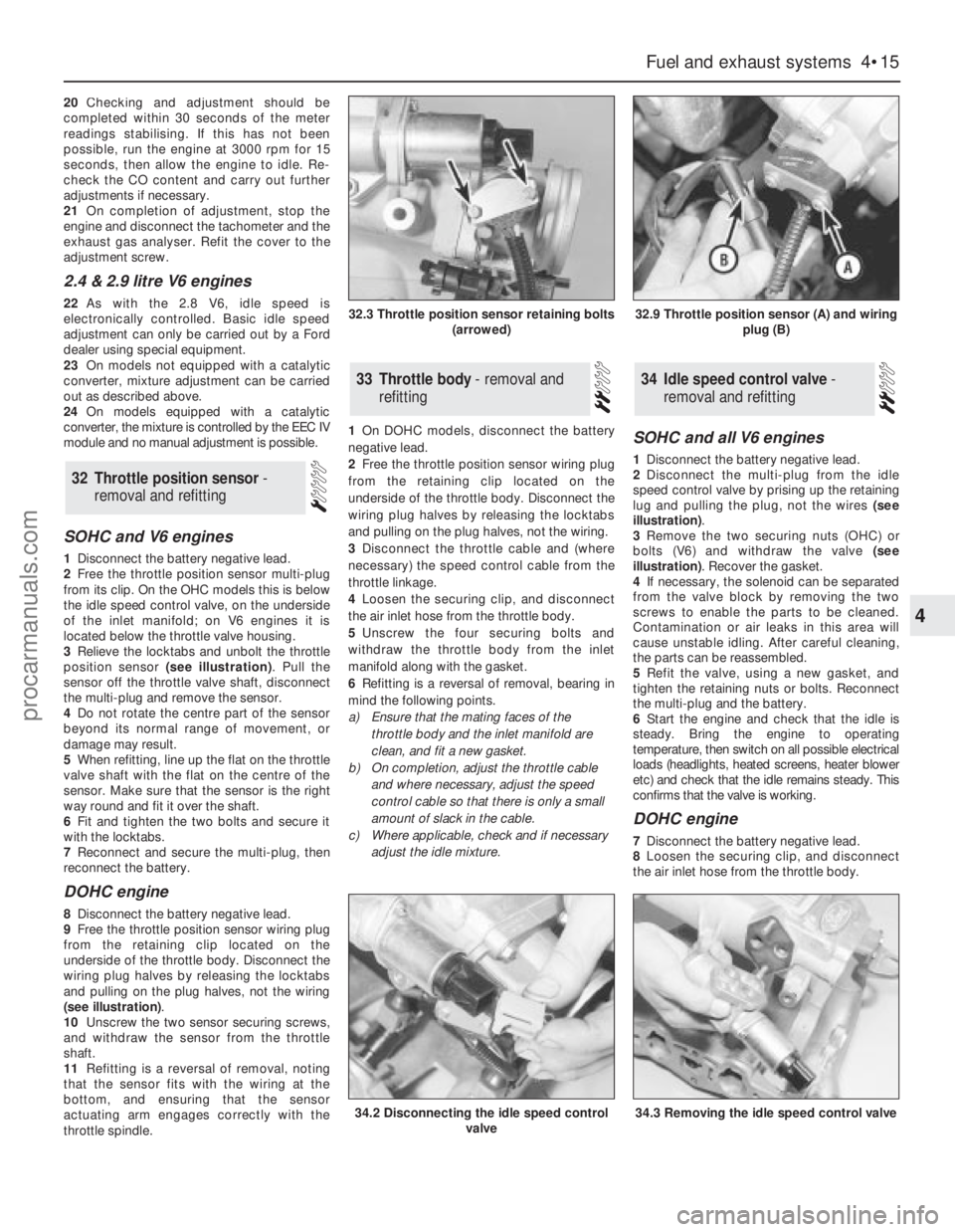
position sensor (see illustration). Pull the
sensor off the throttle valve shaft, disconnect
the multi-plug and remove the sensor.
4Do not rotate the centre part of the sensor
beyond its normal range of movement, or
damage may result.
5When refitting, line up the flat on the throttle
valve shaft with the flat on the centre of the
sensor. Make sure that the sensor is the right
way round and fit it over the shaft.
6Fit and tighten the two bolts and secure it
with the locktabs.
7Reconnect and secure the multi-plug, then
reconnect the battery.
DOHC engine
8Disconnect the battery negative lead.
9Free the throttle position sensor wiring plug
from the retaining clip located on the
underside of the throttle body. Disconnect the
wiring plug halves by releasing the locktabs
and pulling on the plug halves, not the wiring
(see illustration).
10Unscrew the two sensor securing screws,
and withdraw the sensor from the throttle
shaft.
11Refitting is a reversal of removal, noting
that the sensor fits with the wiring at the
bottom, and ensuring that the sensor
actuating arm engages correctly with the
throttle spindle.1On DOHC models, disconnect the battery
negative lead.
2Free the throttle position sensor wiring plug
from the retaining clip located on the
underside of the throttle body. Disconnect the
wiring plug halves by releasing the locktabs
and pulling on the plug halves, not the wiring.
3Disconnect the throttle cable and (where
necessary) the speed control cable from the
throttle linkage.
4Loosen the securing clip, and disconnect
the air inlet hose from the throttle body.
5Unscrew the four securing bolts and
withdraw the throttle body from the inlet
manifold along with the gasket.
6Refitting is a reversal of removal, bearing in
mind the following points.
a)Ensure that the mating faces of the
throttle body and the inlet manifold are
clean, and fit a new gasket.
b)On completion, adjust the throttle cable
and where necessary, adjust the speed
control cable so that there is only a small
amount of slack in the cable.
c)Where applicable, check and if necessary
adjust the idle mixture.
SOHC and all V6 engines
1Disconnect the battery negative lead.
2Disconnect the multi-plug from the idle
speed control valve by prising up the retaining
lug and pulling the plug, not the wires (see
illustration).
3Remove the two securing nuts (OHC) or
bolts (V6) and withdraw the valve (see
illustration). Recover the gasket.
4If necessary, the solenoid can be separated
from the valve block by removing the two
screws to enable the parts to be cleaned.
Contamination or air leaks in this area will
cause unstable idling. After careful cleaning,
the parts can be reassembled.
5Refit the valve, using a new gasket, and
tighten the retaining nuts or bolts. Reconnect
the multi-plug and the battery.
6Start the engine and check that the idle is
steady. Bring the engine to operating
temperature, then switch on all possible electrical
loads (headlights, heated screens, heater blower
etc) and check that the idle remains steady. This
confirms that the valve is working.
DOHC engine
7Disconnect the battery negative lead.
8Loosen the securing clip, and disconnect
the air inlet hose from the throttle body.
34Idle speed control valve -
removal and refitting33Throttle body - removal and
refitting
32Throttle position sensor -
removal and refitting
Fuel and exhaust systems 4•15
4
32.3 Throttle position sensor retaining bolts
(arrowed)32.9 Throttle position sensor (A) and wiring
plug (B)
34.2 Disconnecting the idle speed control
valve34.3 Removing the idle speed control valve
procarmanuals.com
Page 109 of 255
9Unscrew the securing nut, and release the
air inlet tube from the bracket on the engine
compartment front panel.
10Disconnect the wiring plug from the idle
speed control valve.
11Release the air cleaner lid securing clips,
then remove the air inlet tube, plenum
chamber, and air cleaner lid as an assembly,
disconnecting the breather hose from the air
inlet tube.
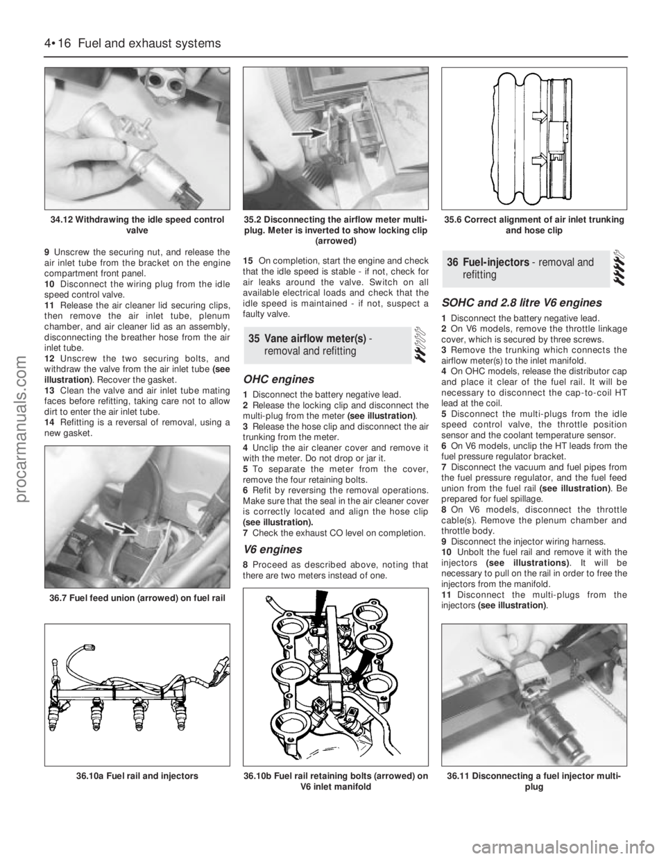
12Unscrew the two securing bolts, and
withdraw the valve from the air inlet tube (see
illustration). Recover the gasket.
13Clean the valve and air inlet tube mating
faces before refitting, taking care not to allow
dirt to enter the air inlet tube.
14Refitting is a reversal of removal, using a
new gasket.15On completion, start the engine and check
that the idle speed is stable - if not, check for
air leaks around the valve. Switch on all
available electrical loads and check that the
idle speed is maintained - if not, suspect a
faulty valve.
OHC engines
1Disconnect the battery negative lead.
2Release the locking clip and disconnect the
multi-plug from the meter (see illustration).
3Release the hose clip and disconnect the air
trunking from the meter.
4Unclip the air cleaner cover and remove it
with the meter. Do not drop or jar it.
5To separate the meter from the cover,
remove the four retaining bolts.
6Refit by reversing the removal operations.
Make sure that the seal in the air cleaner cover
is correctly located and align the hose clip
(seeillustration).
7Check the exhaust CO level on completion.
V6 engines
8Proceed as described above, noting that
there are two meters instead of one.
SOHC and 2.8 litre V6 engines
1Disconnect the battery negative lead.
2On V6 models, remove the throttle linkage
cover, which is secured by three screws.
3Remove the trunking which connects the
airflow meter(s) to the inlet manifold.
4On OHCmodels, release the distributor cap
and place it clear of the fuel rail. It will be
necessary to disconnect the cap-to-coil HT
lead at the coil.
5Disconnect the multi-plugs from the idle
speed control valve, the throttle position
sensor and the coolant temperature sensor.
6On V6 models, unclip the HT leads from the
fuel pressure regulator bracket.
7Disconnect the vacuum and fuel pipes from
the fuel pressure regulator, and the fuel feed
union from the fuel rail (see illustration). Be
prepared for fuel spillage.
8On V6 models, disconnect the throttle
cable(s). Remove the plenum chamber and
throttle body.
9Disconnect the injector wiring harness.
10Unbolt the fuel rail and remove it with the
injectors (see illustrations). It will be
necessary to pull on the rail in order to free the
injectors from the manifold.
11Disconnect the multi-plugs from the
injectors (see illustration).
36Fuel-injectors - removal and
refitting
35Vane airflow meter(s) -
removal and refitting
4•16Fuel and exhaust systems
34.12 Withdrawing the idle speed control
valve
36.7 Fuel feed union (arrowed) on fuel rail
36.10a Fuel rail and injectors36.10b Fuel rail retaining bolts (arrowed) on
V6 inlet manifold36.11 Disconnecting a fuel injector multi-
plug
35.2 Disconnecting the airflow meter multi-
plug. Meter is inverted to show locking clip
(arrowed)35.6 Correct alignment of air inlet trunking
and hose clip
procarmanuals.com
Page 110 of 255
12Extract the retaining clips and pull the
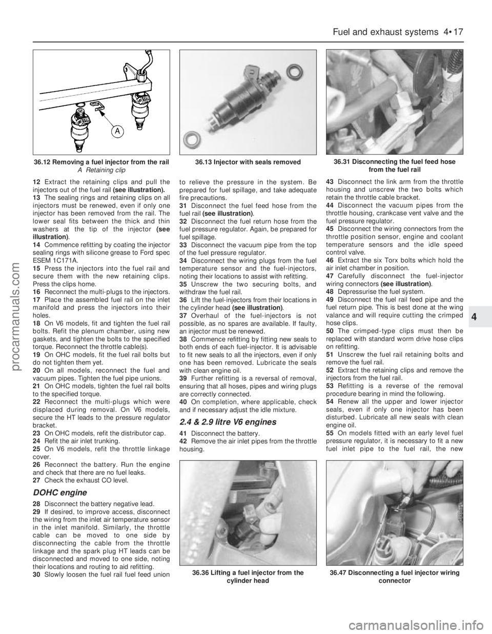
injectors out of the fuel rail(see illustration).
13The sealing rings and retaining clips on all
injectors must be renewed, even if only one
injector has been removed from the rail. The
lower seal fits between the thick and thin
washers at the tip of the injector (see
illustration).
14Commence refitting by coating the injector
sealing rings with silicone grease to Ford spec
ESEM 1C171A.
15Press the injectors into the fuel rail and
secure them with the new retaining clips.
Press the clips home.
16Reconnect the multi-plugs to the injectors.
17Place the assembled fuel rail on the inlet
manifold and press the injectors into their
holes.
18On V6 models, fit and tighten the fuel rail
bolts. Refit the plenum chamber, using new
gaskets, and tighten the bolts to the specified
torque. Reconnect the throttle cable(s).
19On OHCmodels, fit the fuel rail bolts but
do not tighten them yet.
20On all models, reconnect the fuel and
vacuum pipes. Tighten the fuel pipe unions.
21On OHCmodels, tighten the fuel rail bolts
to the specified torque.
22Reconnect the multi-plugs which were
displaced during removal. On V6 models,
secure the HT leads to the pressure regulator
bracket.
23On OHCmodels, refit the distributor cap.
24Refit the air inlet trunking.
25On V6 models, refit the throttle linkage
cover.
26Reconnect the battery. Run the engine
and check that there are no fuel leaks.
27Check the exhaust CO level.
DOHC engine
28Disconnect the battery negative lead.
29If desired, to improve access, disconnect
the wiring from the inlet air temperature sensor
in the inlet manifold. Similarly, the throttle
cable can be moved to one side by
disconnecting the cable from the throttle
linkage and the spark plug HT leads can be
disconnected and moved to one side, noting
their locations and routing to aid refitting.
30Slowly loosen the fuel rail fuel feed unionto relieve the pressure in the system. Be
prepared for fuel spillage, and take adequate
fire precautions.
31Disconnect the fuel feed hose from the
fuel rail (see illustration).
32Disconnect the fuel return hose from the
fuel pressure regulator. Again, be prepared for
fuel spillage.
33Disconnect the vacuum pipe from the top
of the fuel pressure regulator.
34Disconnect the wiring plugs from the fuel
temperature sensor and the fuel-injectors,
noting their locations to assist with refitting.
35Unscrew the two securing bolts, and
withdraw the fuel rail.
36Lift the fuel-injectors from their locations in
the cylinder head (see illustration).
37Overhaul of the fuel-injectors is not
possible, as no spares are available. If faulty,
an injector must be renewed.
38Commence refitting by fitting new seals to
both ends of each fuel-injector. It is advisable
to fit new seals to all the injectors, even if only
one has been removed. Lubricate the seals
with clean engine oil.
39Further refitting is a reversal of removal,
ensuring that all hoses, pipes and wiring plugs
are correctly connected.
40On completion, where applicable, check
and if necessary adjust the idle mixture.
2.4 & 2.9 litre V6 engines
41Disconnect the battery.
42Remove the air inlet pipes from the throttle
housing.43Disconnect the link arm from the throttle
housing and unscrew the two bolts which
retain the throttle cable bracket.
44Disconnect the vacuum pipes from the
throttle housing, crankcase vent valve and the
fuel pressure regulator.
45Disconnect the wiring connectors from the
throttle position sensor, engine and coolant
temperature sensors and the idle speed
control valve.
46Extract the six Torx bolts which hold the
air inlet chamber in position.
47Carefully disconnect the fuel-injector
wiring connectors (see illustration).
48Depressurise the fuel system.
49Disconnect the fuel rail feed pipe and the
fuel return pipe. This is best done at the wing
valance and will require cutting the crimped
hose clips.
50The crimped-type clips must then be
replaced with standard worm drive hose clips
on refitting.
51Unscrew the fuel rail retaining bolts and
remove the fuel rail.
52Extract the retaining clips and remove the
injectors from the fuel rail.
53Refitting is a reverse of the removal
procedure bearing in mind the following.
54Renew all the upper and lower injector
seals, even if only one injector has been
disturbed. Lubricate all new seals with clean
engine oil.
55On models fitted with an early level fuel
pressure regulator, it is necessary to fit a new
fuel inlet pipe to the fuel rail, the new
Fuel and exhaust systems 4•17
4
36.12 Removing a fuel injector from the rail
A Retaining clip36.13 Injector with seals removed36.31 Disconnecting the fuel feed hose
from the fuel rail
36.36 Lifting a fuel injector from the
cylinder head36.47 Disconnecting a fuel injector wiring
connector
procarmanuals.com
Page 111 of 255
connector is supplied with a captive “tell-tale”
ring, the purpose being to hold the connector
teeth retracted. When the two halves of the
connector are pressed together, the ring is
ejected to show that the connection has been
successfully made. Fit the fuel pipe connector
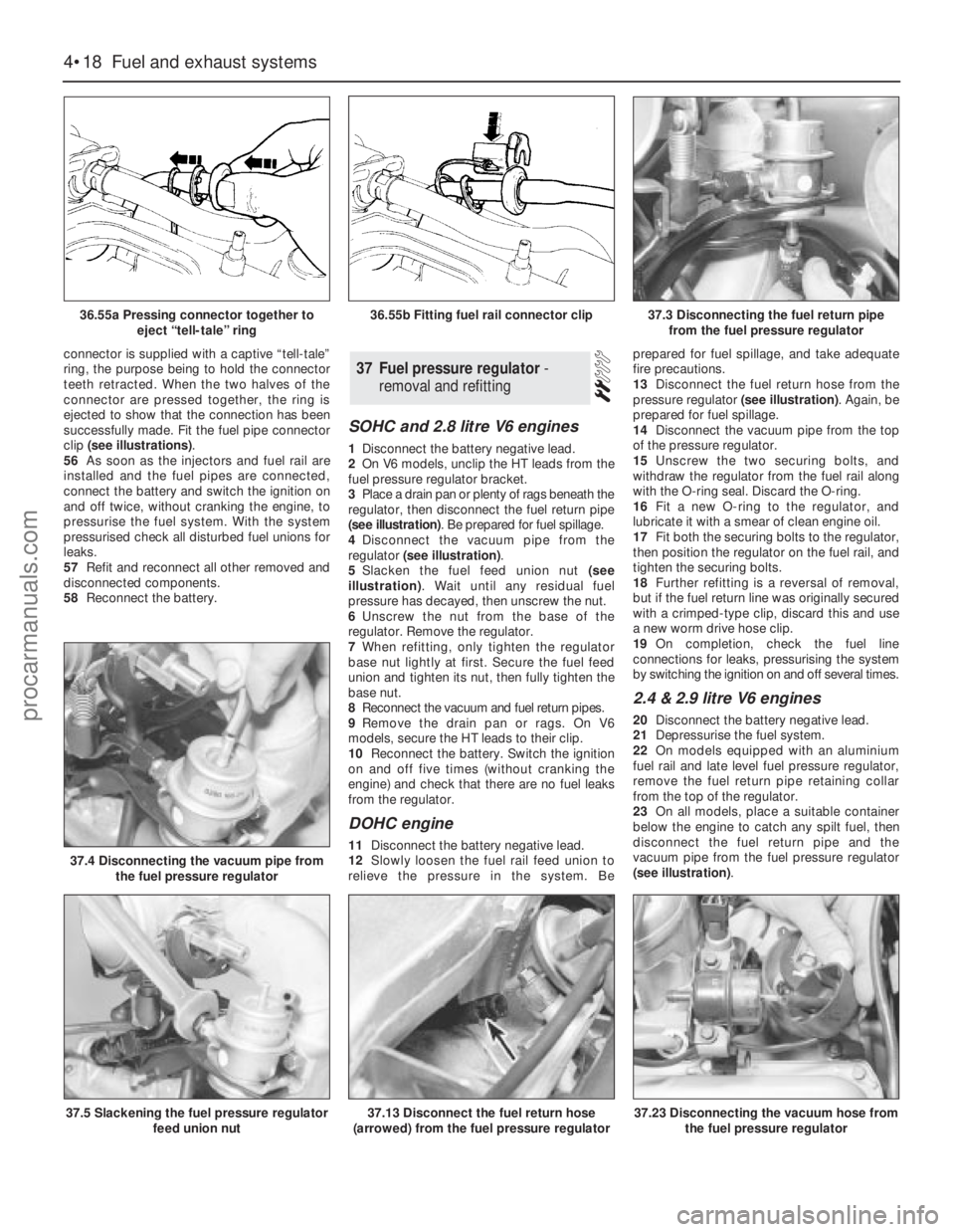
clip (see illustrations).
56As soon as the injectors and fuel rail are
installed and the fuel pipes are connected,
connect the battery and switch the ignition on
and off twice, without cranking the engine, to
pressurise the fuel system. With the system
pressurised check all disturbed fuel unions for
leaks.
57Refit and reconnect all other removed and
disconnected components.
58Reconnect the battery.
SOHC and 2.8 litre V6 engines
1Disconnect the battery negative lead.
2On V6 models, unclip the HT leads from the
fuel pressure regulator bracket.
3Place a drain pan or plenty of rags beneath the
regulator, then disconnect the fuel return pipe
(see illustration). Be prepared for fuel spillage.
4Disconnect the vacuum pipe from the
regulator (see illustration).
5Slacken the fuel feed union nut (see
illustration). Wait until any residual fuel
pressure has decayed, then unscrew the nut.
6Unscrew the nut from the base of the
regulator. Remove the regulator.
7When refitting, only tighten the regulator
base nut lightly at first. Secure the fuel feed
union and tighten its nut, then fully tighten the
base nut.
8Reconnect the vacuum and fuel return pipes.
9Remove the drain pan or rags. On V6
models, secure the HT leads to their clip.
10Reconnect the battery. Switch the ignition
on and off five times (without cranking the
engine) and check that there are no fuel leaks
from the regulator.
DOHC engine
11Disconnect the battery negative lead.
12Slowly loosen the fuel rail feed union to
relieve the pressure in the system. Beprepared for fuel spillage, and take adequate
fire precautions.
13Disconnect the fuel return hose from the
pressure regulator (see illustration). Again, be
prepared for fuel spillage.
14Disconnect the vacuum pipe from the top
of the pressure regulator.
15Unscrew the two securing bolts, and
withdraw the regulator from the fuel rail along
with the O-ring seal. Discard the O-ring.
16Fit a new O-ring to the regulator, and
lubricate it with a smear of clean engine oil.
17Fit both the securing bolts to the regulator,
then position the regulator on the fuel rail, and
tighten the securing bolts.
18Further refitting is a reversal of removal,
but if the fuel return line was originally secured
with a crimped-type clip, discard this and use
a new worm drive hose clip.
19On completion, check the fuel line
connections for leaks, pressurising the system
by switching the ignition on and off several times.
2.4 & 2.9 litre V6 engines
20Disconnect the battery negative lead.
21Depressurise the fuel system.
22On models equipped with an aluminium
fuel rail and late level fuel pressure regulator,
remove the fuel return pipe retaining collar
from the top of the regulator.
23On all models, place a suitable container
below the engine to catch any spilt fuel, then
disconnect the fuel return pipe and the
vacuum pipe from the fuel pressure regulator
(see illustration).
37Fuel pressure regulator -
removal and refitting
4•18Fuel and exhaust systems
36.55a Pressing connector together to
eject “tell-tale” ring
37.4 Disconnecting the vacuum pipe from
the fuel pressure regulator
37.5 Slackening the fuel pressure regulator
feed union nut37.13 Disconnect the fuel return hose
(arrowed) from the fuel pressure regulator37.23 Disconnecting the vacuum hose from
the fuel pressure regulator
36.55b Fitting fuel rail connector clip37.3 Disconnecting the fuel return pipe
from the fuel pressure regulator
procarmanuals.com
Page 112 of 255
24Unbolt and remove the regulator from the
fuel rail. Remove the sealing O-ring and
discard it; a new one must be used on
refitting.
25Refitting is a reverse of the removal
procedure applying a smear of clean engine oil
to the new regulator O-ring. On models
equipped with a late level regulator, ensure
that the return pipe is securely held in position
by the retaining collar.
26On completion, switch the ignition on and
off five times without cranking the engine to
pressurise the fuel system.
27With the system pressurised check all
disturbed fuel unions for signs of leakage.
1The potentiometer is located on the right-
hand side of the engine compartment, behind
the MAP sensor.
2Disconnect the battery negative lead.
3Remove the securing screw, then withdraw
the potentiometer and disconnect the wiring
plug.
4Refitting is a reversal of removal. On
completion adjust the idle mixture.1On 2.4 & 2.9 litre V6 engines, disconnect the
battery.
2Disconnect the switch wiring connector.
3Slacken and remove the switch from the
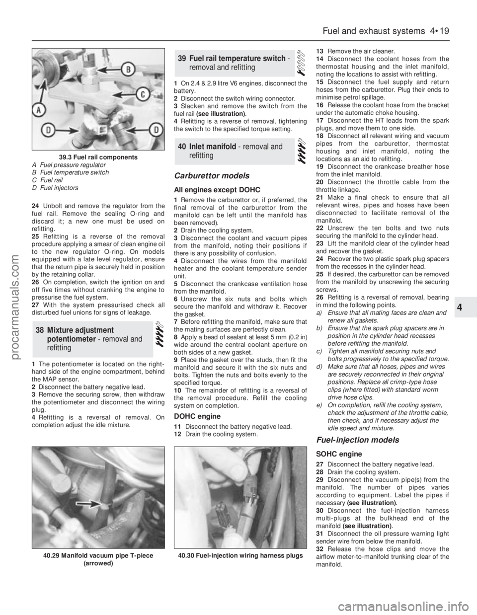
fuel rail (see illustration).
4Refitting is a reverse of removal, tightening
the switch to the specified torque setting.
Carburettor models
All engines except DOHC
1Remove the carburettor or, if preferred, the
final removal of the carburettor from the
manifold can be left until the manifold has
been removed).
2Drain the cooling system.
3Disconnect the coolant and vacuum pipes
from the manifold, noting their positions if
there is any possibility of confusion.
4Disconnect the wires from the manifold
heater and the coolant temperature sender
unit.
5Disconnect the crankcase ventilation hose
from the manifold.
6Unscrew the six nuts and bolts which
secure the manifold and withdraw it. Recover
the gasket.
7Before refitting the manifold, make sure that
the mating surfaces are perfectly clean.
8Apply a bead of sealant at least 5 mm (0.2 in)
wide around the central coolant aperture on
both sides of a new gasket.
9Place the gasket over the studs, then fit the
manifold and secure it with the six nuts and
bolts. Tighten the nuts and bolts evenly to the
specified torque.
10The remainder of refitting is a reversal of
the removal procedure. Refill the cooling
system on completion.
DOHC engine
11Disconnect the battery negative lead.
12Drain the cooling system.13Remove the air cleaner.
14Disconnect the coolant hoses from the
thermostat housing and the inlet manifold,
noting the locations to assist with refitting.
15Disconnect the fuel supply and return
hoses from the carburettor. Plug their ends to
minimise petrol spillage.
16Release the coolant hose from the bracket
under the automatic choke housing.
17Disconnect the HT leads from the spark
plugs, and move them to one side.
18Disconnect all relevant wiring and vacuum
pipes from the carburettor, thermostat
housing and inlet manifold, noting the
locations as an aid to refitting.
19Disconnect the crankcase breather hose
from the inlet manifold.
20Disconnect the throttle cable from the
throttle linkage.
21Make a final check to ensure that all
relevant wires, pipes and hoses have been
disconnected to facilitate removal of the
manifold.
22Unscrew the ten bolts and two nuts
securing the manifold to the cylinder head.
23Lift the manifold clear of the cylinder head
and recover the gasket.
24Recover the two plastic spark plug spacers
from the recesses in the cylinder head.
25If desired, the carburettor can be removed
from the manifold by unscrewing the securing
screws.
26Refitting is a reversal of removal, bearing
in mind the following points.
a)Ensure that all mating faces are clean and
renew all gaskets.
b)Ensure that the spark plug spacers are in
position in the cylinder head recesses
before refitting the manifold.
c)Tighten all manifold securing nuts and
bolts progressively to the specified torque.
d)Make sure that all hoses, pipes and wires
are securely reconnected in their original
positions. Replace all crimp-type hose
clips (where fitted) with standard worm
drive hose clips.
e)On completion, refill the cooling system,
check the adjustment of the throttle cable,
then check, and if necessary adjust the
idle speed and mixture.
Fuel-injection models
SOHC engine
27Disconnect the battery negative lead.
28Drain the cooling system.
29Disconnect the vacuum pipe(s) from the
manifold. The number of pipes varies
according to equipment. Label the pipes if
necessary (see illustration).
30Disconnect the fuel-injection harness
multi-plugs at the bulkhead end of the
manifold (see illustration).
31Disconnect the oil pressure warning light
sender wire from below the manifold.
32Release the hose clips and move the
airflow meter-to-manifold trunking clear of the
manifold.
40Inlet manifold - removal and
refitting
39Fuel rail temperature switch -
removal and refitting
38Mixture adjustment
potentiometer - removal and
refitting
Fuel and exhaust systems 4•19
4
39.3 Fuel rail components
A Fuel pressure regulator
B Fuel temperature switch
C Fuel rail
D Fuel injectors
40.29 Manifold vacuum pipe T-piece
(arrowed)40.30 Fuel-injection wiring harness plugs
procarmanuals.com
 1
1 2
2 3
3 4
4 5
5 6
6 7
7 8
8 9
9 10
10 11
11 12
12 13
13 14
14 15
15 16
16 17
17 18
18 19
19 20
20 21
21 22
22 23
23 24
24 25
25 26
26 27
27 28
28 29
29 30
30 31
31 32
32 33
33 34
34 35
35 36
36 37
37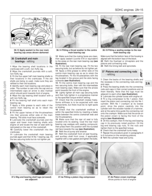 38
38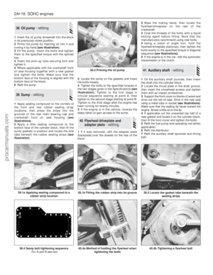 39
39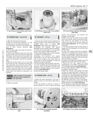 40
40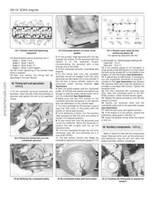 41
41 42
42 43
43 44
44 45
45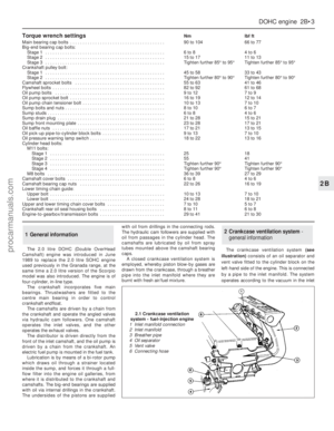 46
46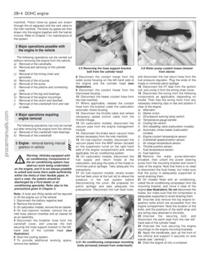 47
47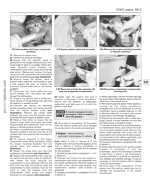 48
48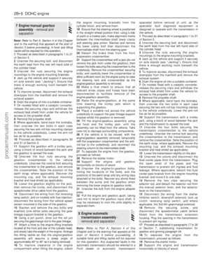 49
49 50
50 51
51 52
52 53
53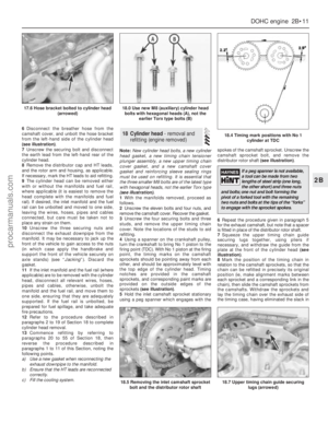 54
54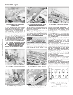 55
55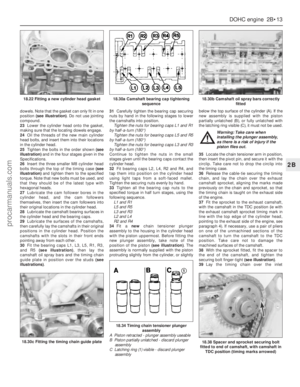 56
56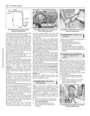 57
57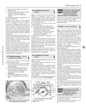 58
58 59
59 60
60 61
61 62
62 63
63 64
64 65
65 66
66 67
67 68
68 69
69 70
70 71
71 72
72 73
73 74
74 75
75 76
76 77
77 78
78 79
79 80
80 81
81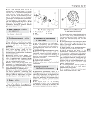 82
82 83
83 84
84 85
85 86
86 87
87 88
88 89
89 90
90 91
91 92
92 93
93 94
94 95
95 96
96 97
97 98
98 99
99 100
100 101
101 102
102 103
103 104
104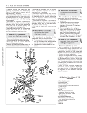 105
105 106
106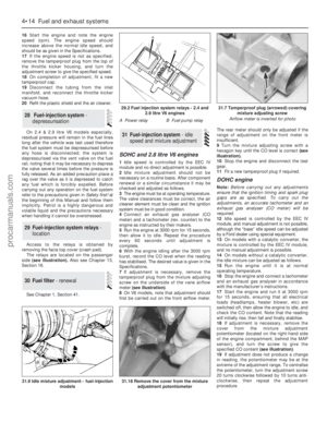 107
107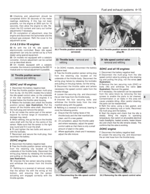 108
108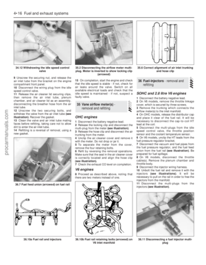 109
109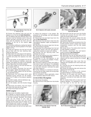 110
110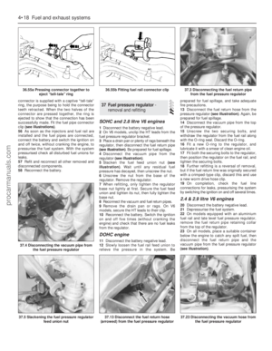 111
111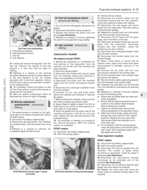 112
112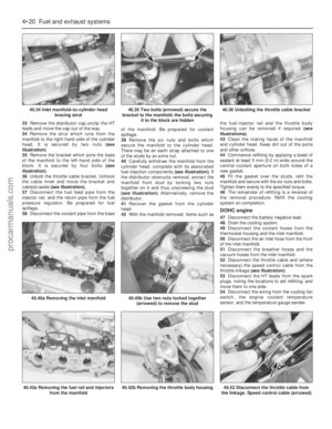 113
113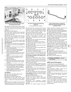 114
114 115
115 116
116 117
117 118
118 119
119 120
120 121
121 122
122 123
123 124
124 125
125 126
126 127
127 128
128 129
129 130
130 131
131 132
132 133
133 134
134 135
135 136
136 137
137 138
138 139
139 140
140 141
141 142
142 143
143 144
144 145
145 146
146 147
147 148
148 149
149 150
150 151
151 152
152 153
153 154
154 155
155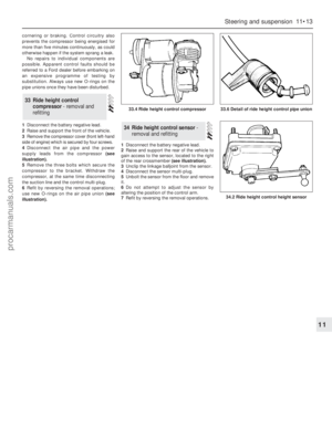 156
156 157
157 158
158 159
159 160
160 161
161 162
162 163
163 164
164 165
165 166
166 167
167 168
168 169
169 170
170 171
171 172
172 173
173 174
174 175
175 176
176 177
177 178
178 179
179 180
180 181
181 182
182 183
183 184
184 185
185 186
186 187
187 188
188 189
189 190
190 191
191 192
192 193
193 194
194 195
195 196
196 197
197 198
198 199
199 200
200 201
201 202
202 203
203 204
204 205
205 206
206 207
207 208
208 209
209 210
210 211
211 212
212 213
213 214
214 215
215 216
216 217
217 218
218 219
219 220
220 221
221 222
222 223
223 224
224 225
225 226
226 227
227 228
228 229
229 230
230 231
231 232
232 233
233 234
234 235
235 236
236 237
237 238
238 239
239 240
240 241
241 242
242 243
243 244
244 245
245 246
246 247
247 248
248 249
249 250
250 251
251 252
252 253
253 254
254


