1985 FORD GRANADA roof rack
[x] Cancel search: roof rackPage 102 of 255
1Check the cost and availability of spare parts
before deciding to dismantle the carburettor. If
the unit has seen much service, fitting a new or
reconditioned carburettor may prove more
satisfactory than any attempt at overhaul.
2Obtain a carburettor repair kit, which will
contain the necessary gaskets, diaphragms
and other renewable items.
3With the carburettor removed from the
vehicle, clean it thoroughly externally and
place it on a clean worksurface.
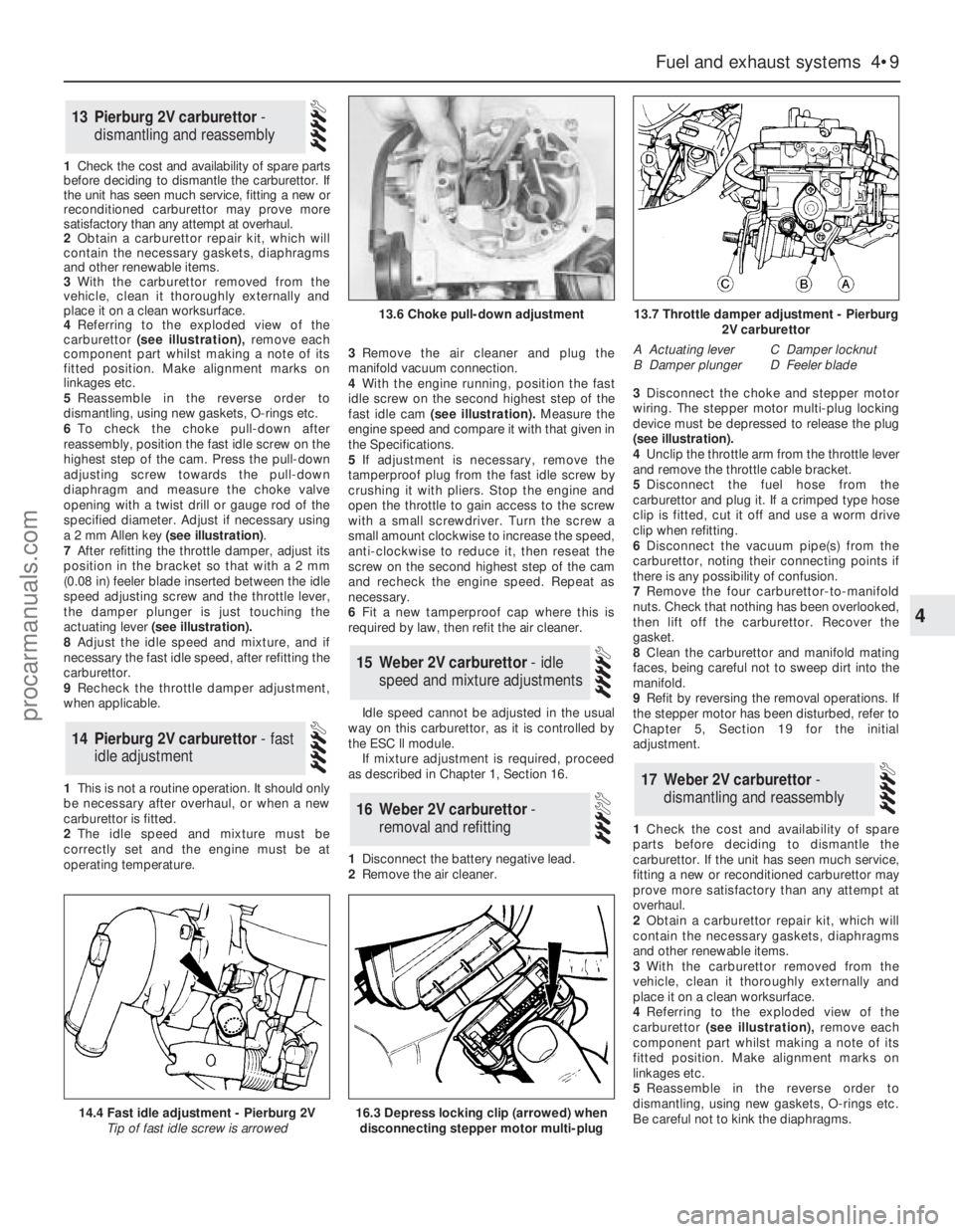
4 Referringto the exploded view of the
carburettor(see illustration),remove each
component part whilst making a note of its
fitted position. Make alignment marks on
linkages etc.
5Reassemble in the reverse order to
dismantling, using new gaskets, O-rings etc.
6To check the choke pull-down after
reassembly, position the fast idle screw on the
highest step of the cam. Press the pull-down
adjusting screw towards the pull-down
diaphragm and measure the choke valve
opening with a twist drill or gauge rod of the
specified diameter. Adjust if necessary using
a 2 mm Allen key (see illustration).
7After refitting the throttle damper, adjust its
position in the bracket so that with a 2 mm
(0.08 in) feeler blade inserted between the idle
speed adjusting screw and the throttle lever,
the damper plunger is just touching the
actuating lever(see illustration).
8Adjust the idle speed and mixture, and if
necessary the fast idle speed, after refitting the
carburettor.
9Recheck the throttle damper adjustment,
when applicable.
1This is not a routine operation. It should only
be necessary after overhaul, or when a new
carburettor is fitted.
2The idle speed and mixture must be
correctly set and the engine must be at
operating temperature.3Remove the air cleaner and plug the
manifold vacuum connection.
4With the engine running, position the fast
idle screw on the second highest step of the
fast idle cam(see illustration).Measure the
engine speed and compare it with that given in
the Specifications.
5If adjustment is necessary, remove the
tamperproof plug from the fast idle screw by
crushing it with pliers. Stop the engine and
open the throttle to gain access to the screw
with a small screwdriver. Turn the screw a
small amount clockwise to increase the speed,
anti-clockwise to reduce it, then reseat the
screw on the second highest step of the cam
and recheck the engine speed. Repeat as
necessary.
6Fit a new tamperproof cap where this is
required by law, then refit the air cleaner.
Idle speed cannot be adjusted in the usual
way on this carburettor, as it is controlled by
the ESC ll module.
If mixture adjustment is required, proceed
as described in Chapter 1, Section 16.
1Disconnect the battery negative lead.
2Remove the air cleaner.3Disconnect the choke and stepper motor
wiring. The stepper motor multi-plug locking
device must be depressed to release the plug
(seeillustration).
4Unclip the throttle arm from the throttle lever
and remove the throttle cable bracket.
5Disconnect the fuel hose from the
carburettor and plug it. If a crimped type hose
clip is fitted, cut it off and use a worm drive
clip when refitting.
6Disconnect the vacuum pipe(s) from the
carburettor, noting their connecting points if
there is any possibility of confusion.
7Remove the four carburettor-to-manifold
nuts. Check that nothing has been overlooked,
then lift off the carburettor. Recover the
gasket.
8Clean the carburettor and manifold mating
faces, being careful not to sweep dirt into the
manifold.
9Refit by reversing the removal operations. If
the stepper motor has been disturbed, refer to
Chapter 5, Section 19 for the initial
adjustment.
1Check the cost and availability of spare
parts before deciding to dismantle the
carburettor. If the unit has seen much service,
fitting a new or reconditioned carburettor may
prove more satisfactory than any attempt at
overhaul.
2Obtain a carburettor repair kit, which will
contain the necessary gaskets, diaphragms
and other renewable items.
3With the carburettor removed from the
vehicle, clean it thoroughly externally and
place it on a clean worksurface.
4 Referringto the exploded view of the
carburettor(see illustration),remove each
component part whilst making a note of its
fitted position. Make alignment marks on
linkages etc.
5Reassemble in the reverse order to
dismantling, using new gaskets, O-rings etc.
Be careful not to kink the diaphragms.
17Weber 2V carburettor -
dismantling and reassembly
16Weber 2V carburettor -
removal and refitting
15Weber 2V carburettor - idle
speed and mixture adjustments
14Pierburg 2V carburettor - fast
idle adjustment
13Pierburg 2V carburettor -
dismantling and reassembly
Fuel and exhaust systems 4•9
4
14.4 Fast idle adjustment - Pierburg 2V
Tip of fast idle screw is arrowed
13.6 Choke pull-down adjustment13.7 Throttle damper adjustment - Pierburg
2V carburettor
A Actuating lever
B Damper plungerC Damper locknut
D Feeler blade
16.3 Depress locking clip (arrowed) when
disconnecting stepper motor multi-plug
procarmanuals.com
Page 127 of 255
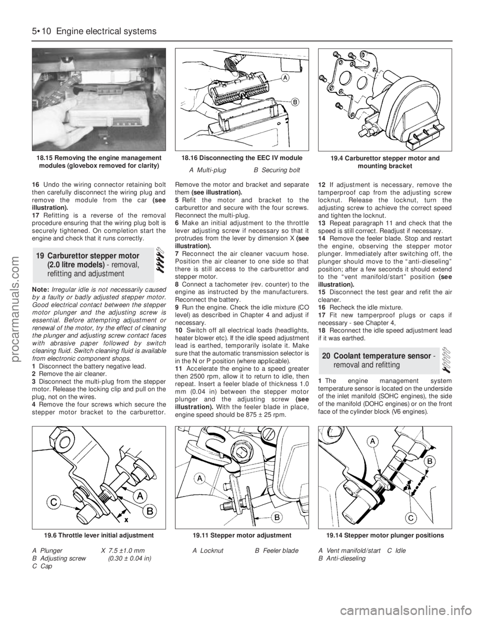
16Undo the wiring connector retaining bolt
then carefully disconnect the wiring plug and
remove the module from the car (see
illustration).
17Refitting is a reverse of the removal
procedure ensuring that the wiring plug bolt is
securely tightened. On completion start the
engine and check that it runs correctly.
Note: Irregular idle is not necessarily caused
by a faulty or badly adjusted stepper motor.
Good electrical contact between the stepper
motor plunger and the adjusting screw is
essential. Before attempting adjustment or
renewal of the motor, try the effect of cleaning
the plunger and adjusting screw contact faces
with abrasive paper followed by switch
cleaning fluid. Switch cleaning fluid is available
from electronic component shops.
1Disconnect the battery negative lead.
2Remove the air cleaner.
3Disconnect the multi-plug from the stepper
motor. Release the locking clip and pull on the
plug, not on the wires.
4Remove the four screws which secure the
stepper motor bracket to the carburettor.Remove the motor and bracket and separate
them (see illustration).
5Refit the motor and bracket to the
carburettor and secure with the four screws.
Reconnect the multi-plug.
6Make an initial adjustment to the throttle
lever adjusting screw if necessary so that it
protrudes from the lever by dimension X (see
illustration).
7Reconnect the air cleaner vacuum hose.
Position the air cleaner to one side so that
there is still access to the carburettor and
stepper motor.
8Connect a tachometer (rev. counter) to the
engine as instructed by the manufacturers.
Reconnect the battery.
9Run the engine. Check the idle mixture (CO
level) as described in Chapter 4 and adjust if
necessary.
10Switch off all electrical loads (headlights,
heater blower etc). If the idle speed adjustment
lead is earthed, temporarily isolate it. Make
sure that the automatic transmission selector is
in the N or P position (where applicable).
11Accelerate the engine to a speed greater
then 2500 rpm, allow it to return to idle, then
repeat. Insert a feeler blade of thickness 1.0
mm (0.04 in) between the stepper motor
plunger and the adjusting screw(see
illustration).With the feeler blade in place,
engine speed should be 875 ±25 rpm. 12If adjustment is necessary, remove the
tamperproof cap from the adjusting screw
locknut. Release the locknut, turn the
adjusting screw to achieve the correct speed
and tighten the locknut.
13Repeat paragraph 11 and check that the
speed is still correct. Readjust if necessary.
14Remove the feeler blade. Stop and restart
the engine, observing the stepper motor
plunger. Immediately after switching off, the
plunger should move to the “anti-dieseling”
position; after a few seconds it should extend
to the “vent manifold/start” position (see
illustration).
15Disconnect the test gear and refit the air
cleaner.
16Recheck the idle mixture.
17Fit new tamperproof plugs or caps if
necessary - see Chapter 4,
18Reconnect the idle speed adjustment lead
if it was earthed.
1The engine management system
temperature sensor is located on the underside
of the inlet manifold (SOHC engines), the side
of the manifold (DOHC engines) or on the front
face of the cylinder block (V6 engines).
20Coolant temperature sensor -
removal and refitting
19Carburettor stepper motor
(2.0 litre models) - removal,
refitting and adjustment
5•10Engine electrical systems
18.16 Disconnecting the EEC IV module
A Multi-plugB Securing bolt
19.6 Throttle lever initial adjustment
A Plunger
B Adjusting screw
C CapX 7.5 ±1.0 mm
(0.30 ±0.04 in)
19.11 Stepper motor adjustment
A LocknutB Feeler blade
19.14 Stepper motor plunger positions
A Vent manifold/start
B Anti-dieselingC Idle
19.4 Carburettor stepper motor and
mounting bracket18.15 Removing the engine management
modules (glovebox removed for clarity)
procarmanuals.com
Page 163 of 255
3Apply masking tape to the front and sides of
the roof aperture to protect the paintwork.
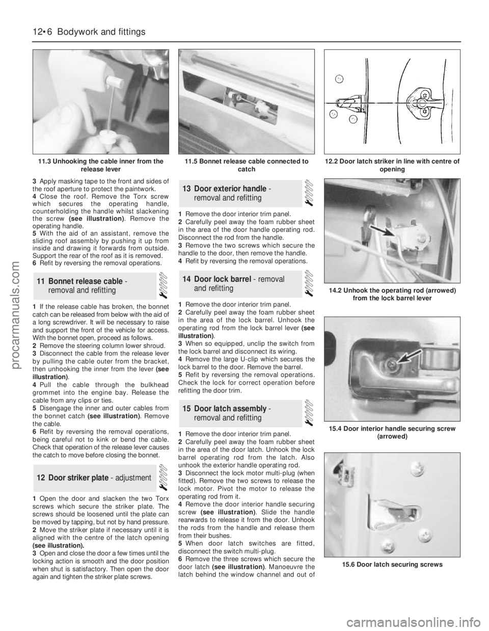
4Close the roof. Remove the Torx screw
which secures the operating handle,
counterholding the handle whilst slackening
the screw (see illustration). Remove the
operating handle.
5With the aid of an assistant, remove the
sliding roof assembly by pushing it up from
inside and drawing it forwards from outside.
Support the rear of the roof as it is removed.
6Refit by reversing the removal operations.
1If the release cable has broken, the bonnet
catch can be released from below with the aid of
a long screwdriver. It will be necessary to raise
and support the front of the vehicle for access.
With the bonnet open, proceed as follows.
2Remove the steering column lower shroud.
3Disconnect the cable from the release lever
by pulling the cable outer from the bracket,
then unhooking the inner from the lever (see
illustration).
4Pull the cable through the bulkhead
grommet into the engine bay. Release the
cable from any clips or ties.
5Disengage the inner and outer cables from
the bonnet catch (see illustration). Remove
the cable.
6Refit by reversing the removal operations,
being careful not to kink or bend the cable.
Check that operation of the release lever causes
the catch to move before closing the bonnet.
1Open the door and slacken the two Torx
screws which secure the striker plate. The
screws should be loosened until the plate can
be moved by tapping, but not by hand pressure.
2Move the striker plate if necessary until it is
aligned with the centre of the latch opening
(see illustration).
3Open and close the door a few times until the
locking action is smooth and the door position
when shut is satisfactory. Then open the door
again and tighten the striker plate screws.1Remove the door interior trim panel.
2Carefully peel away the foam rubber sheet
in the area of the door handle operating rod.
Disconnect the rod from the handle.
3Remove the two screws which secure the
handle to the door, then remove the handle.
4Refit by reversing the removal operations.
1Remove the door interior trim panel.
2Carefully peel away the foam rubber sheet
in the area of the lock barrel. Unhook the
operating rod from the lock barrel lever (see
illustration).
3When so equipped, unclip the switch from
the lock barrel and disconnect its wiring.
4Remove the large U-clip which secures the
lock barrel to the door. Remove the barrel.
5Refit by reversing the removal operations.
Check the lock for correct operation before
refitting the door trim.
1Remove the door interior trim panel.
2Carefully peel away the foam rubber sheet
in the area of the door latch. Unhook the lock
barrel operating rod from the latch. Also
unhook the exterior handle operating rod.
3Disconnect the lock motor multi-plug (when
fitted). Remove the two screws to release the
lock motor. Pivot the motor to release the
operating rod from it.
4Remove the door interior handle securing
screw (see illustration). Slide the handle
rearwards to release it from the door. Unhook
the rods from the handle and release them
from their bushes.
5When door latch switches are fitted,
disconnect the switch multi-plug.
6Remove the three screws which secure the
door latch (see illustration). Manoeuvre the
latch behind the window channel and out of
15Door latch assembly -
removal and refitting
14Door lock barrel - removal
and refitting
13Door exterior handle -
removal and refitting
12Door striker plate - adjustment
11Bonnet release cable -
removal and refitting
12•6Bodywork and fittings
11.3 Unhooking the cable inner from the
release lever
14.2 Unhook the operating rod (arrowed)
from the lock barrel lever
15.4 Door interior handle securing screw
(arrowed)
15.6 Door latch securing screws
11.5 Bonnet release cable connected to
catch12.2 Door latch striker in line with centre of
opening
procarmanuals.com
Page 189 of 255
20When refitting, check the switch for
correct operation before refitting the shrouds
and steering wheel centre cover. When fitting
the shrouds, be careful not to trap the switch
rubber gaiter.
Models from April 1992
21Note that if access to the switch retaining
screws cannot be gained with the steering
wheel in position, then the steering wheel
must first be removed.
Windscreen wipe/wash switch
Models before April 1992
22Proceed as described in the previous sub-
section for the direction indicator switch.
Depending on equipment, the wipe/wash
switch may have more than one multi-plug
connected to it.
Models from April 1992
23Note that if access to the switch retaining
screws cannot be gained with the steering
wheel in position, then the steering wheel
must first be removed.
Door pillar switch (for courtesy
light)
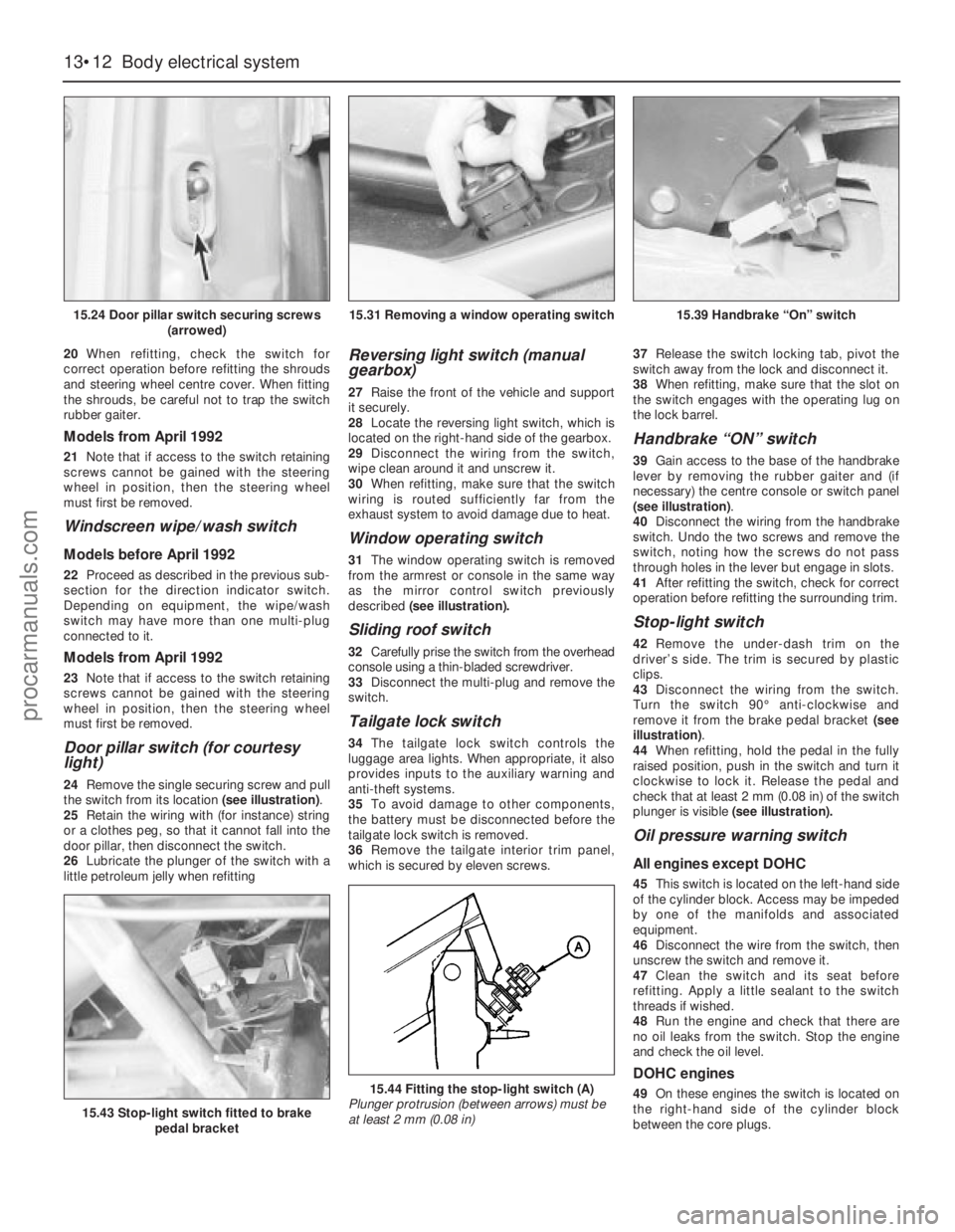
24Remove the single securing screw and pull
the switch from its location (see illustration).
25Retain the wiring with (for instance) string
or a clothes peg, so that it cannot fall into the
door pillar, then disconnect the switch.
26Lubricate the plunger of the switch with a
little petroleum jelly when refitting
Reversing light switch (manual
gearbox)
27Raise the front of the vehicle and support
it securely.
28Locate the reversing light switch, which is
located on the right-hand side of the gearbox.
29Disconnect the wiring from the switch,
wipe clean around it and unscrew it.
30When refitting, make sure that the switch
wiring is routed sufficiently far from the
exhaust system to avoid damage due to heat.
Window operating switch
31The window operating switch is removed
from the armrest or console in the same way
as the mirror control switch previously
described (see illustration).
Sliding roof switch
32Carefully prise the switch from the overhead
console using a thin-bladed screwdriver.
33Disconnect the multi-plug and remove the
switch.
Tailgate lock switch
34The tailgate lock switch controls the
luggage area lights. When appropriate, it also
provides inputs to the auxiliary warning and
anti-theft systems.
35To avoid damage to other components,
the battery must be disconnected before the
tailgate lock switch is removed.
36Remove the tailgate interior trim panel,
which is secured by eleven screws.37Release the switch locking tab, pivot the
switch away from the lock and disconnect it.
38When refitting, make sure that the slot on
the switch engages with the operating lug on
the lock barrel.
Handbrake “ON” switch
39Gain access to the base of the handbrake
lever by removing the rubber gaiter and (if
necessary) the centre console or switch panel
(see illustration).
40Disconnect the wiring from the handbrake
switch. Undo the two screws and remove the
switch, noting how the screws do not pass
through holes in the lever but engage in slots.
41After refitting the switch, check for correct
operation before refitting the surrounding trim.
Stop-light switch
42Remove the under-dash trim on the
driver’s side. The trim is secured by plastic
clips.
43Disconnect the wiring from the switch.
Turn the switch 90°anti-clockwise and
remove it from the brake pedal bracket (see
illustration).
44When refitting, hold the pedal in the fully
raised position, push in the switch and turn it
clockwise to lock it. Release the pedal and
check that at least 2 mm (0.08 in) of the switch
plunger is visible (see illustration).
Oil pressure warning switch
All engines except DOHC
45This switch is located on the left-hand side
of the cylinder block. Access may be impeded
by one of the manifolds and associated
equipment.
46Disconnect the wire from the switch, then
unscrew the switch and remove it.
47Clean the switch and its seat before
refitting. Apply a little sealant to the switch
threads if wished.
48Run the engine and check that there are
no oil leaks from the switch. Stop the engine
and check the oil level.
DOHC engines
49On these engines the switch is located on
the right-hand side of the cylinder block
between the core plugs.
13•12Body electrical system
15.24 Door pillar switch securing screws
(arrowed)
15.43 Stop-light switch fitted to brake
pedal bracket
15.44 Fitting the stop-light switch (A)
Plunger protrusion (between arrows) must be
at least 2 mm (0.08 in)
15.31 Removing a window operating switch15.39 Handbrake “On” switch
procarmanuals.com
Page 193 of 255
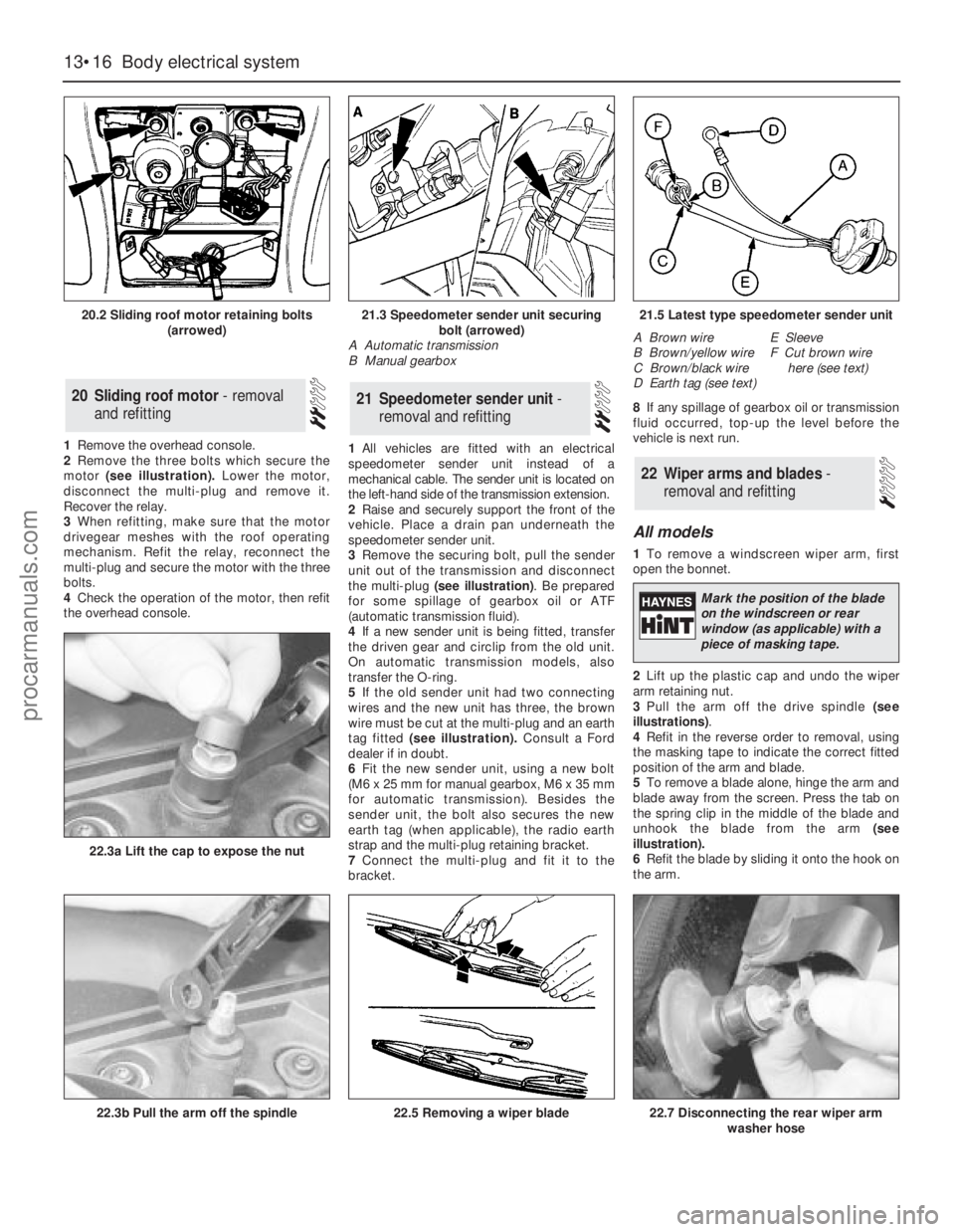
1Remove the overhead console.
2Remove the three bolts which secure the
motor (see illustration).Lower the motor,
disconnect the multi-plug and remove it.
Recover the relay.
3When refitting, make sure that the motor
drivegear meshes with the roof operating
mechanism. Refit the relay, reconnect the
multi-plug and secure the motor with the three
bolts.
4Check the operation of the motor, then refit
the overhead console.1All vehicles are fitted with an electrical
speedometer sender unit instead of a
mechanical cable. The sender unit is located on
the left-hand side of the transmission extension.
2Raise and securely support the front of the
vehicle. Place a drain pan underneath the
speedometer sender unit.
3Remove the securing bolt, pull the sender
unit out of the transmission and disconnect
the multi-plug (see illustration). Be prepared
for some spillage of gearbox oil or ATF
(automatic transmission fluid).
4If a new sender unit is being fitted, transfer
the driven gear and circlip from the old unit.
On automatic transmission models, also
transfer the O-ring.
5If the old sender unit had two connecting
wires and the new unit has three, the brown
wire must be cut at the multi-plug and an earth
tag fitted (see illustration).Consult a Ford
dealer if in doubt.
6Fit the new sender unit, using a new bolt
(M6 x 25 mm for manual gearbox, M6 x 35 mm
for automatic transmission). Besides the
sender unit, the bolt also secures the new
earth tag (when applicable), the radio earth
strap and the multi-plug retaining bracket.
7Connect the multi-plug and fit it to the
bracket.8If any spillage of gearbox oil or transmission
fluid occurred, top-up the level before the
vehicle is next run.
All models
1To remove a windscreen wiper arm, first
open the bonnet.
2Lift up the plastic cap and undo the wiper
arm retaining nut.
3Pull the arm off the drive spindle (see
illustrations).
4Refit in the reverse order to removal, using
the masking tape to indicate the correct fitted
position of the arm and blade.
5To remove a blade alone, hinge the arm and
blade away from the screen. Press the tab on
the spring clip in the middle of the blade and
unhook the blade from the arm (see
illustration).
6Refit the blade by sliding it onto the hook on
the arm.
22Wiper arms and blades -
removal and refitting
21Speedometer sender unit -
removal and refitting20Sliding roof motor - removal
and refitting
13•16Body electrical system
20.2 Sliding roof motor retaining bolts
(arrowed)
22.3b Pull the arm off the spindle
22.3a Lift the cap to expose the nut
22.5 Removing a wiper blade22.7 Disconnecting the rear wiper arm
washer hose
21.3 Speedometer sender unit securing
bolt (arrowed)
A Automatic transmission
B Manual gearbox21.5 Latest type speedometer sender unit
A Brown wire
B Brown/yellow wire
C Brown/black wire
D Earth tag (see text)E Sleeve
F Cut brown wire
here (see text)
Mark the position of the blade
on the windscreen or rear
window (as applicable) with a
piece of masking tape.
procarmanuals.com
Page 199 of 255
High frequency units
14Remove the instrument panel surround
and the facia top.
15Remove the two screws which secure the
speaker bracket. Disconnect the wiring and
withdraw the speaker and bracket together.
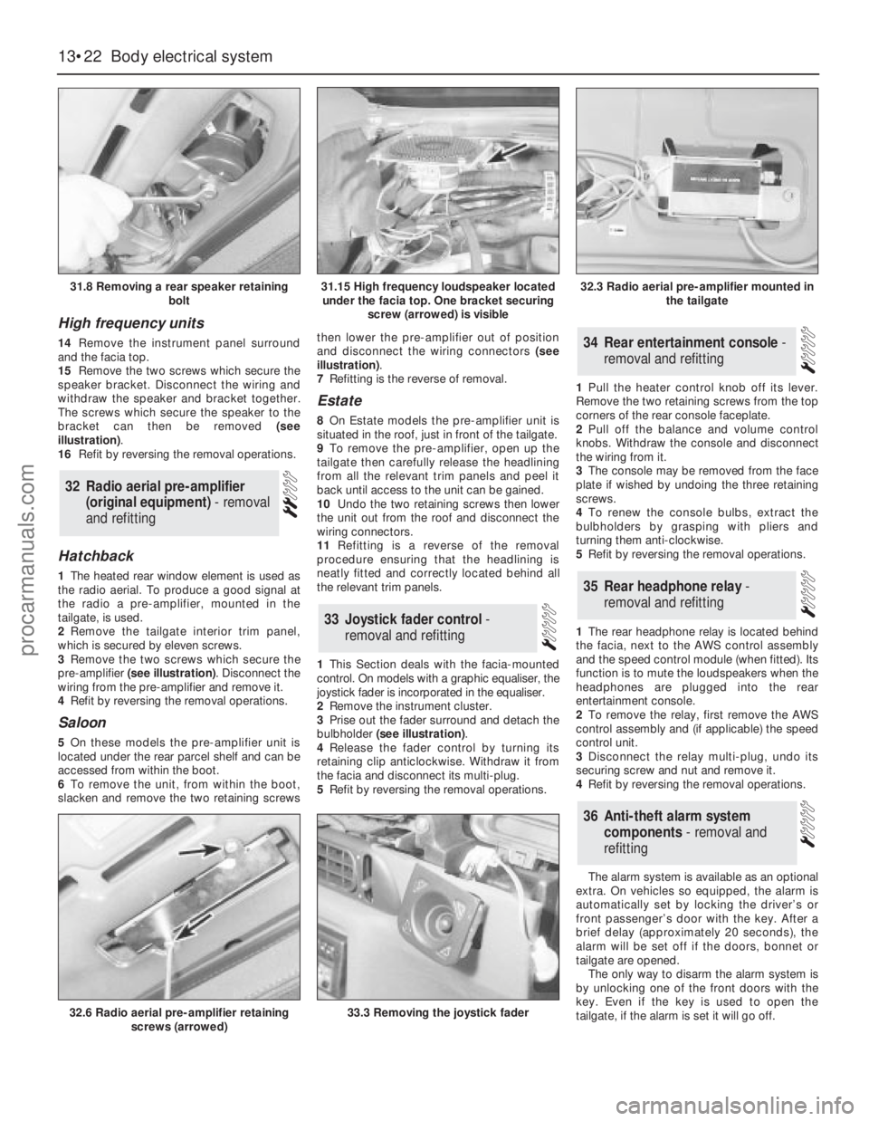
The screws which secure the speaker to the
bracket can then be removed (see
illustration).
16Refit by reversing the removal operations.
Hatchback
1The heated rear window element is used as
the radio aerial. To produce a good signal at
the radio a pre-amplifier, mounted in the
tailgate, is used.
2Remove the tailgate interior trim panel,
which is secured by eleven screws.
3Remove the two screws which secure the
pre-amplifier (see illustration). Disconnect the
wiring from the pre-amplifier and remove it.
4Refit by reversing the removal operations.
Saloon
5On these models the pre-amplifier unit is
located under the rear parcel shelf and can be
accessed from within the boot.
6To remove the unit, from within the boot,
slacken and remove the two retaining screwsthen lower the pre-amplifier out of position
and disconnect the wiring connectors (see
illustration).
7Refitting is the reverse of removal.
Estate
8On Estate models the pre-amplifier unit is
situated in the roof, just in front of the tailgate.
9To remove the pre-amplifier, open up the
tailgate then carefully release the headlining
from all the relevant trim panels and peel it
back until access to the unit can be gained.
10Undo the two retaining screws then lower
the unit out from the roof and disconnect the
wiring connectors.
11Refitting is a reverse of the removal
procedure ensuring that the headlining is
neatly fitted and correctly located behind all
the relevant trim panels.
1This Section deals with the facia-mounted
control. On models with a graphic equaliser, the
joystick fader is incorporated in the equaliser.
2Remove the instrument cluster.
3Prise out the fader surround and detach the
bulbholder (see illustration).
4Release the fader control by turning its
retaining clip anticlockwise. Withdraw it from
the facia and disconnect its multi-plug.
5Refit by reversing the removal operations.1Pull the heater control knob off its lever.
Remove the two retaining screws from the top
corners of the rear console faceplate.
2Pull off the balance and volume control
knobs. Withdraw the console and disconnect
the wiring from it.
3The console may be removed from the face
plate if wished by undoing the three retaining
screws.
4To renew the console bulbs, extract the
bulbholders by grasping with pliers and
turning them anti-clockwise.
5Refit by reversing the removal operations.
1The rear headphone relay is located behind
the facia, next to the AWS control assembly
and the speed control module (when fitted). Its
function is to mute the loudspeakers when the
headphones are plugged into the rear
entertainment console.
2To remove the relay, first remove the AWS
control assembly and (if applicable) the speed
control unit.
3Disconnect the relay multi-plug, undo its
securing screw and nut and remove it.
4Refit by reversing the removal operations.
The alarm system is available as an optional
extra. On vehicles so equipped, the alarm is
automatically set by locking the driver’s or
front passenger’s door with the key. After a
brief delay (approximately 20 seconds), the
alarm will be set off if the doors, bonnet or
tailgate are opened.
The only way to disarm the alarm system is
by unlocking one of the front doors with the
key. Even if the key is used to open the
tailgate, if the alarm is set it will go off.
36Anti-theft alarm system
components - removal and
refitting
35Rear headphone relay -
removal and refitting
34Rear entertainment console -
removal and refitting
33Joystick fader control -
removal and refitting
32Radio aerial pre-amplifier
(original equipment) - removal
and refitting
13•22Body electrical system
31.8 Removing a rear speaker retaining
bolt
32.6 Radio aerial pre-amplifier retaining
screws (arrowed)33.3 Removing the joystick fader
31.15 High frequency loudspeaker located
under the facia top. One bracket securing
screw (arrowed) is visible32.3 Radio aerial pre-amplifier mounted in
the tailgate
procarmanuals.com
Page 238 of 255
REF•3
The following list contains only those tools and
instruments freely available to the public, and not
those special tools produced by the vehicle
manufacturer specifically for its dealer network.
You will find occasional references to these
manufacturer’s special tools in the text of this
manual. Generally, an alternative method of doing
the job without the vehicle manufacturer’s special
tool is given. However, sometimes there is no
alternative to using them. Where this is the case
and the relevant tool cannot be bought or
borrowed, you will have to entrust the work to a
franchised garage.
MValve spring compressor (see illustration)
MValve grinding tool
MPiston ring compressor (see illustration)
MPiston ring removal/installation tool (see
illustration)
MCylinder bore hone (see illustration)
MBalljoint separator
MCoil spring compressors (where applicable)
MTwo/three-legged hub and bearing puller
(see illustration)
MImpact screwdriver
MMicrometer and/or vernier calipers (see
illustrations)
MDial gauge (see illustration)
MStroboscopic timing light (see illustration)
MDwell angle meter/tachometer
MUniversal electrical multi-meter
MCylinder compression gauge (see
illustration)
MHand-operated vacuum pump and gauge
(see illustration)
MClutch plate alignment set (see
illustration)
MBrake shoe steady spring cup removal tool
(see illustration)
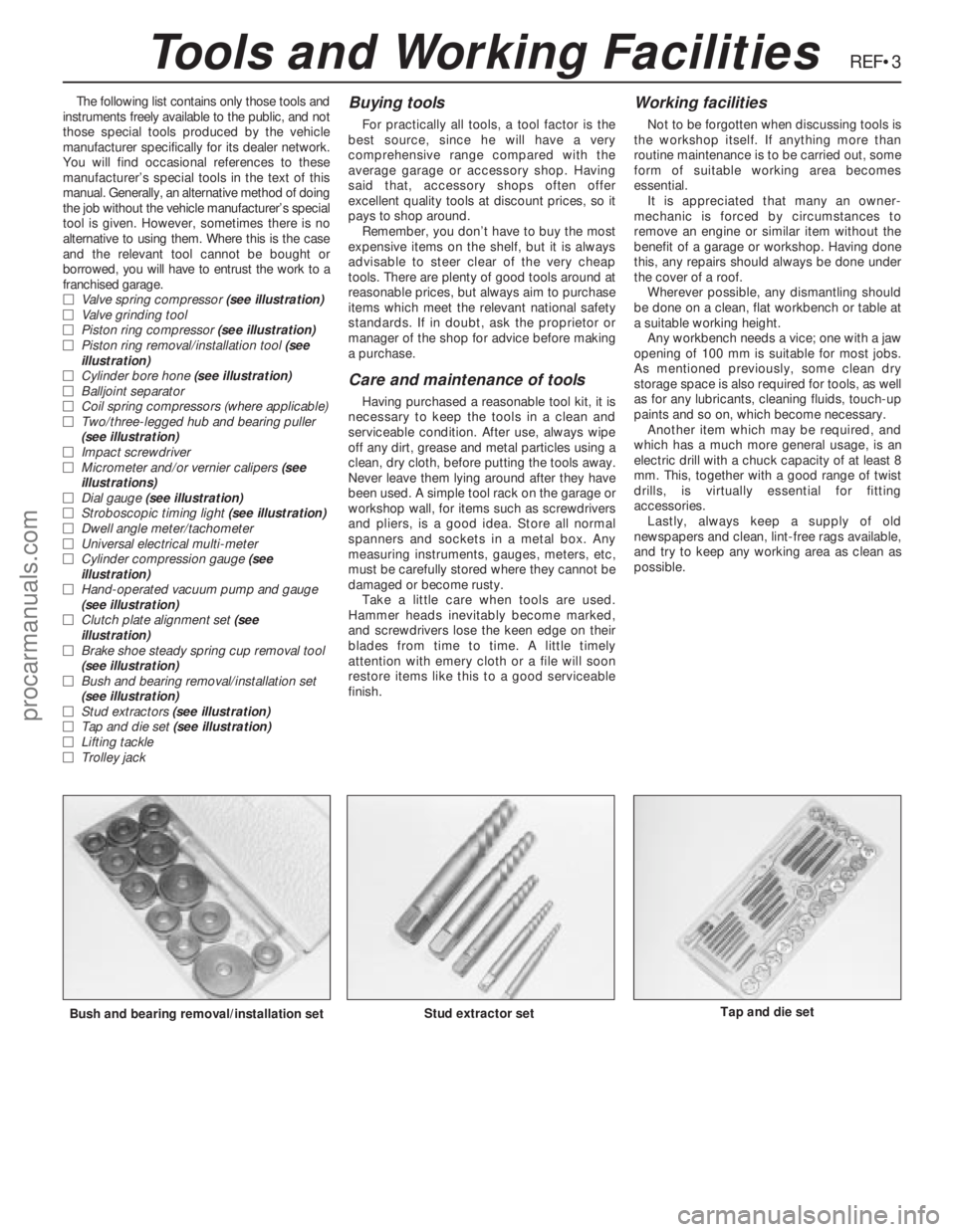
MBush and bearing removal/installation set
(see illustration)
MStud extractors (see illustration)
MTap and die set (see illustration)
MLifting tackle
MTrolley jackBuying tools
For practically all tools, a tool factor is the
best source, since he will have a very
comprehensive range compared with the
average garage or accessory shop. Having
said that, accessory shops often offer
excellent quality tools at discount prices, so it
pays to shop around.
Remember, you don’t have to buy the most
expensive items on the shelf, but it is always
advisable to steer clear of the very cheap
tools. There are plenty of good tools around at
reasonable prices, but always aim to purchase
items which meet the relevant national safety
standards. If in doubt, ask the proprietor or
manager of the shop for advice before making
a purchase.
Care and maintenance of tools
Having purchased a reasonable tool kit, it is
necessary to keep the tools in a clean and
serviceable condition. After use, always wipe
off any dirt, grease and metal particles using a
clean, dry cloth, before putting the tools away.
Never leave them lying around after they have
been used. A simple tool rack on the garage or
workshop wall, for items such as screwdrivers
and pliers, is a good idea. Store all normal
spanners and sockets in a metal box. Any
measuring instruments, gauges, meters, etc,
must be carefully stored where they cannot be
damaged or become rusty.
Take a little care when tools are used.
Hammer heads inevitably become marked,
and screwdrivers lose the keen edge on their
blades from time to time. A little timely
attention with emery cloth or a file will soon
restore items like this to a good serviceable
finish.
Working facilities
Not to be forgotten when discussing tools is
the workshop itself. If anything more than
routine maintenance is to be carried out, some
form of suitable working area becomes
essential.
It is appreciated that many an owner-
mechanic is forced by circumstances to
remove an engine or similar item without the
benefit of a garage or workshop. Having done
this, any repairs should always be done under
the cover of a roof.
Wherever possible, any dismantling should
be done on a clean, flat workbench or table at
a suitable working height.
Any workbench needs a vice; one with a jaw
opening of 100 mm is suitable for most jobs.
As mentioned previously, some clean dry
storage space is also required for tools, as well
as for any lubricants, cleaning fluids, touch-up
paints and so on, which become necessary.
Another item which may be required, and
which has a much more general usage, is an
electric drill with a chuck capacity of at least 8
mm. This, together with a good range of twist
drills, is virtually essential for fitting
accessories.
Lastly, always keep a supply of old
newspapers and clean, lint-free rags available,
and try to keep any working area as clean as
possible.
Bush and bearing removal/installation setStud extractor setTap and die set
Tools and Working Facilities
procarmanuals.com
Page 239 of 255
REF•4
Whenever servicing, repair or overhaul work
is carried out on the car or its components, it is
necessary to observe the following procedures
and instructions. This will assist in carrying out
the operation efficiently and to a professional
standard of workmanship.
Joint mating faces and gaskets
When separating components at their
mating faces, never insert screwdrivers or
similar implements into the joint between the
faces in order to prise them apart. This can
cause severe damage which results in oil
leaks, coolant leaks, etc upon reassembly.
Separation is usually achieved by tapping
along the joint with a soft-faced hammer in
order to break the seal. However, note that this
method may not be suitable where dowels are
used for component location.
Where a gasket is used between the mating
faces of two components, ensure that it is
renewed on reassembly, and fit it dry unless
otherwise stated in the repair procedure. Make
sure that the mating faces are clean and dry,
with all traces of old gasket removed. When
cleaning a joint face, use a tool which is not
likely to score or damage the face, and remove
any burrs or nicks with an oilstone or fine file.
Make sure that tapped holes are cleaned
with a pipe cleaner, and keep them free of
jointing compound, if this is being used, unless
specifically instructed otherwise.
Ensure that all orifices, channels or pipes
are clear, and blow through them, preferably
using compressed air.
Oil seals
Oil seals can be removed by levering them
out with a wide flat-bladed screwdriver or
similar implement. Alternatively, a number of
self-tapping screws may be screwed into the
seal, and these used as a purchase for pliers
or some similar device in order to pull the seal
free.
Whenever an oil seal is removed from its
working location, either individually or as part
of an assembly, it should be renewed.
The very fine sealing lip of the seal is easily
damaged, and will not seal if the surface it
contacts is not completely clean and free from
scratches, nicks or grooves.
Protect the lips of the seal from any surface
which may damage them in the course of
fitting. Use tape or a conical sleeve where
possible. Lubricate the seal lips with oil before
fitting and, on dual-lipped seals, fill the space
between the lips with grease.
Unless otherwise stated, oil seals must be
fitted with their sealing lips toward the
lubricant to be sealed.
Use a tubular drift or block of wood of the
appropriate size to install the seal and, if the
seal housing is shouldered, drive the seal
down to the shoulder. If the seal housing is
unshouldered, the seal should be fitted with its
face flush with the housing top face (unless
otherwise instructed).
Screw threads and fastenings
Seized nuts, bolts and screws are quite a
common occurrence where corrosion has set
in, and the use of penetrating oil or releasing
fluid will often overcome this problem if the
offending item is soaked for a while before
attempting to release it. The use of an impact
driver may also provide a means of releasing
such stubborn fastening devices, when used
in conjunction with the appropriate
screwdriver bit or socket. If none of these
methods works, it may be necessary to resort
to the careful application of heat, or the use of
a hacksaw or nut splitter device.
Studs are usually removed by locking two
nuts together on the threaded part, and then
using a spanner on the lower nut to unscrew
the stud. Studs or bolts which have broken off
below the surface of the component in which
they are mounted can sometimes be removed
using a proprietary stud extractor. Always
ensure that a blind tapped hole is completely
free from oil, grease, water or other fluid
before installing the bolt or stud. Failure to do
this could cause the housing to crack due to
the hydraulic action of the bolt or stud as it is
screwed in.
When tightening a castellated nut to accept
a split pin, tighten the nut to the specified
torque, where applicable, and then tighten
further to the next split pin hole. Never slacken
the nut to align the split pin hole, unless stated
in the repair procedure.
When checking or retightening a nut or bolt
to a specified torque setting, slacken the nut
or bolt by a quarter of a turn, and then
retighten to the specified setting. However,
this should not be attempted where angular
tightening has been used.
For some screw fastenings, notably cylinder
head bolts or nuts, torque wrench settings are
no longer specified for the latter stages of
tightening, “angle-tightening” being called up
instead. Typically, a fairly low torque wrench
setting will be applied to the bolts/nuts in
the correct sequence, followed by one or
more stages of tightening through specified
angles.
Locknuts, locktabs and washers
Any fastening which will rotate against a
component or housing in the course of
tightening should always have a washer
between it and the relevant component or
housing.
Spring or split washers should always be
renewed when they are used to lock a critical
component such as a big-end bearing
retaining bolt or nut. Locktabs which are
folded over to retain a nut or bolt should
always be renewed.
Self-locking nuts can be re-used in non-
critical areas, providing resistance can be felt
when the locking portion passes over the bolt
or stud thread. However, it should be noted
that self-locking stiffnuts tend to lose theireffectiveness after long periods of use, and in
such cases should be renewed as a matter of
course.
Split pins must always be replaced with new
ones of the correct size for the hole.
When thread-locking compound is found on
the threads of a fastener which is to be re-
used, it should be cleaned off with a wire
brush and solvent, and fresh compound
applied on reassembly.
Special tools
Some repair procedures in this manual
entail the use of special tools such as a press,
two or three-legged pullers, spring
compressors, etc. Wherever possible, suitable
readily-available alternatives to the
manufacturer’s special tools are described,
and are shown in use. Unless you are highly-
skilled and have a thorough understanding of
the procedures described, never attempt to
bypass the use of any special tool when the
procedure described specifies its use. Not
only is there a very great risk of personal injury,
but expensive damage could be caused to the
components involved.
Environmental considerations
When disposing of used engine oil, brake
fluid, antifreeze, etc, give due consideration to
any detrimental environmental effects. Do not,
for instance, pour any of the above liquids
down drains into the general sewage system,
or onto the ground to soak away. Many local
council refuse tips provide a facility for waste
oil disposal, as do some garages. If none of
these facilities are available, consult your local
Environmental Health Department for further
advice.
With the universal tightening-up of
legislation regarding the emission of
environmentally-harmful substances from
motor vehicles, most current vehicles have
tamperproof devices fitted to the main
adjustment points of the fuel system. These
devices are primarily designed to prevent
unqualified persons from adjusting the fuel/air
mixture, with the chance of a consequent
increase in toxic emissions. If such devices are
encountered during servicing or overhaul, they
should, wherever possible, be renewed or
refitted in accordance with the vehicle
manufacturer’s requirements or current
legislation.
Note: It is
antisocial and
illegal to dump
oil down the
drain. To find
the location of
your local oil
recycling
bank, call this
number free.
General Repair Procedures
procarmanuals.com