1985 FORD GRANADA parking brake
[x] Cancel search: parking brakePage 9 of 255

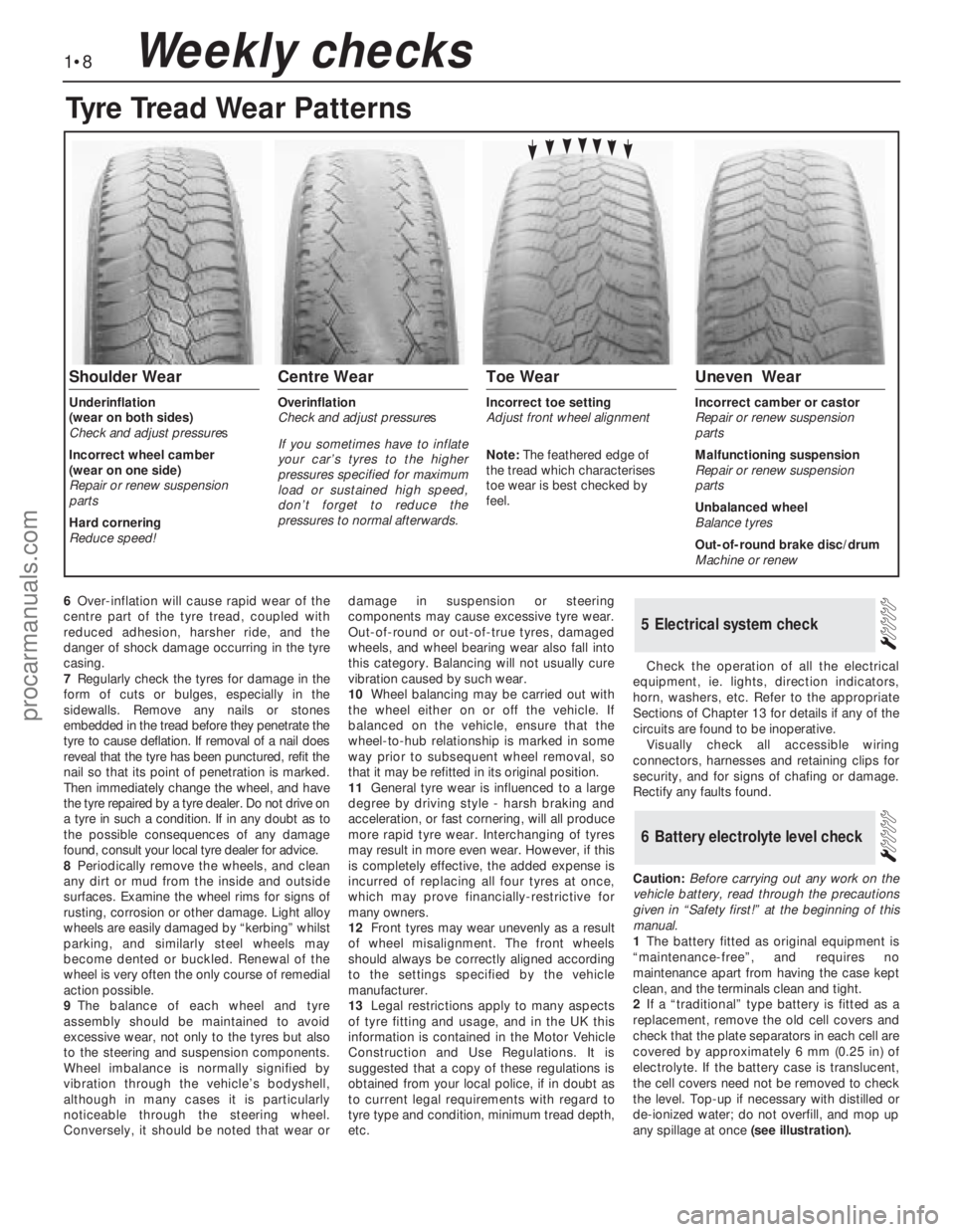
6Over-inflation will cause rapid wear of the
centre part of the tyre tread, coupled with
reduced adhesion, harsher ride, and the
danger of shock damage occurring in the tyre
casing.
7Regularly check the tyres for damage in the
form of cuts or bulges, especially in the
sidewalls. Remove any nails or stones
embedded in the tread before they penetrate the
tyre to cause deflation. If removal of a nail does
reveal that the tyre has been punctured, refit the
nail so that its point of penetration is marked.
Then immediately change the wheel, and have
the tyre repaired by a tyre dealer. Do not drive on
a tyre in such a condition. If in any doubt as to
the possible consequences of any damage
found, consult your local tyre dealer for advice.
8Periodically remove the wheels, and clean
any dirt or mud from the inside and outside
surfaces. Examine the wheel rims for signs of
rusting, corrosion or other damage. Light alloy
wheels are easily damaged by “kerbing” whilst
parking, and similarly steel wheels may
become dented or buckled. Renewal of the
wheel is very often the only course of remedial
action possible.
9The balance of each wheel and tyre
assembly should be maintained to avoid
excessive wear, not only to the tyres but also
to the steering and suspension components.
Wheel imbalance is normally signified by
vibration through the vehicle’s bodyshell,
although in many cases it is particularly
noticeable through the steering wheel.
Conversely, it should be noted that wear ordamage in suspension or steering
components may cause excessive tyre wear.
Out-of-round or out-of-true tyres, damaged
wheels, and wheel bearing wear also fall into
this category. Balancing will not usually cure
vibration caused by such wear.
10Wheel balancing may be carried out with
the wheel either on or off the vehicle. If
balanced on the vehicle, ensure that the
wheel-to-hub relationship is marked in some
way prior to subsequent wheel removal, so
that it may be refitted in its original position.
11General tyre wear is influenced to a large
degree by driving style - harsh braking and
acceleration, or fast cornering, will all produce
more rapid tyre wear. Interchanging of tyres
may result in more even wear. However, if this
is completely effective, the added expense is
incurred of replacing all four tyres at once,
which may prove financially-restrictive for
many owners.
12Front tyres may wear unevenly as a result
of wheel misalignment. The front wheels
should always be correctly aligned according
to the settings specified by the vehicle
manufacturer.
13Legal restrictions apply to many aspects
of tyre fitting and usage, and in the UK this
information is contained in the Motor Vehicle
Construction and Use Regulations. It is
suggested that a copy of these regulations is
obtained from your local police, if in doubt as
to current legal requirements with regard to
tyre type and condition, minimum tread depth,
etc.Check the operation of all the electrical
equipment, ie. lights, direction indicators,
horn, washers, etc. Refer to the appropriate
Sections of Chapter 13 for details if any of the
circuits are found to be inoperative.
Visually check all accessible wiring
connectors, harnesses and retaining clips for
security, and for signs of chafing or damage.
Rectify any faults found.
Caution: Before carrying out any work on the
vehicle battery, read through the precautions
given in “Safety first!” at the beginning of this
manual.
1The battery fitted as original equipment is
“maintenance-free”, and requires no
maintenance apart from having the case kept
clean, and the terminals clean and tight.
2If a “traditional” type battery is fitted as a
replacement, remove the old cell covers and
check that the plate separators in each cell are
covered by approximately 6 mm (0.25 in) of
electrolyte. If the battery case is translucent,
the cell covers need not be removed to check
the level. Top-up if necessary with distilled or
de-ionized water; do not overfill, and mop up
any spillage at once(see illustration).
6Battery electrolyte level check
5Electrical system check
1•8Weekly checks
Tyre Tread Wear Patterns
Shoulder Wear
Underinflation
(wear on both sides)
Check and adjust pressures
Incorrect wheel camber
(wear on one side)
Repair or renew suspension
parts
Hard cornering
Reduce speed!
Centre Wear
Overinflation
Check and adjust pressures
If you sometimes have to inflate
your car’s tyres to the higher
pressures specified for maximum
load or sustained high speed,
don’t forget to reduce the
pressures to normal afterwards.
Toe Wear
Incorrect toe setting
Adjust front wheel alignment
Note: The feathered edge of
the tread which characterises
toe wear is best checked by
feel.
Uneven Wear
Incorrect camber or castor
Repair or renew suspension
parts
Malfunctioning suspension
Repair or renew suspension
parts
Unbalanced wheel
Balance tyres
Out-of-round brake disc/drum
Machine or renew
procarmanuals.com
Page 146 of 255

The steering gear is of rack-and-pinion type.
Power assistance is standard on V6 models
and optional on others. The power-assisted
steering gear has a “variable ratio” effect
which increases the steering ratio about the
straight-ahead position: this provides quick
lock-to-lock action without the penalty of
over-responsiveness in open road driving.
The steering wheel is adjustable both up-
and-down and fore-and-aft. Both steering
column and shaft are designed to collapse
under impact. The steering shaft is connected
to the pinion by an intermediate shaft, which
has a universal joint at its upper end and a
flexible coupling at the lower end.
Front suspension is independent, of the
MacPherson strut type, with coil springs and
concentric telescopic shock absorbers. The
struts are attached to the tops of the stub axle
carriers, which are located at their lower ends
by balljoints incorporated in the lower
suspension arms. The lower suspension arms
pivot at their inner ends, where they are
attached to a central crossmember. The anti-
roll bar is attached to the rear of the arms and
serves to control fore-and-aft movement as
well as reducing roll.
Suspension geometry has been designed to
give good steering “feel”, resistance to pulling
caused by uneven braking effort or tyre
deflation, and (in the case of manual steering)
acceptably low steering wheel effort at parking
speeds. Only toe is adjustable in service.
The rear suspension is also independent. It
is of the semi-trailing arm type, with coil
springs and separate telescopic shock
absorbers. An optionally-available ride height
control system keeps the rear suspension
height constant, regardless of vehicle load.
Both front and rear wheel bearings are of a
special taper-roller type and require no
periodic adjustment in service.1Refer to Chapter 1, Section 35, to check the
power steering fluid level.
2If the fluid level falls so low that air enters
the pump, or after component renewal, the
system must be bled as follows.
3Remove the reservoir filler cap. Top-up with
clean fluid to the appropriate “cold” level. It is
important that the fluid is free of air bubbles,
so do not shake the container when topping-
up, and pour the fluid slowly.
4Disconnect the negative LT lead from the
ignition coil. Have an assistant crank the
engine on the starter in two second bursts, at
the same time turning the steering wheel from
lock to lock. Keep the reservoir topped up
whilst this is going on.
5When air bubbles no longer appear in the
fluid, stop the cranking. Reconnect the coil
negative lead and run the engine for a few
seconds, then stop it and check the level
again. Refit the filler cap.
6Run the vehicle for a few miles to warm up
the fluid and expel any remaining air, then stop
the engine and make a final fluid level check.
Manual steering
1Position the steering in the straight-ahead
position, then remove the ignition key so that
the steering is locked.
2Slacken the front wheel nuts. Raise and
support the front of the vehicle and remove
the front wheels.
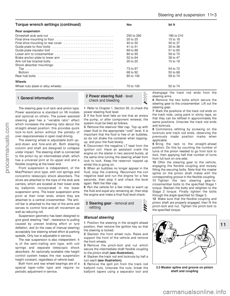
3Remove the pinch-bolt and nut which
secure the intermediate shaft flexible coupling
to the pinion shaft (see illustration).
4Slacken the track rod end locknuts by half a
turn each (see illustration).
5Remove the split pin from the track rod
balljoint nuts. Unscrew the nuts, break the
balljoint tapers using a separator tool anddisengage the track rod ends from the
steering arms.
6Remove the two bolts which secure the
steering gear to the crossmember. Lift out the
steering gear.
7Mark the positions of the track rod ends on
the track rods, using paint or sticky tape, so
that they can be refitted in approximately the
same positions. Unscrew the track rod ends
and locknuts.
8Commence refitting by screwing on the
locknuts and track rod ends, observing the
previously made position marks when
applicable.
9Bring the rack to the straight-ahead
position. Do this by counting the number of
turns of the pinion needed to go from lock to
lock, then applying half that number of turns
from full lock on one side.
10Offer the steering gear to the vehicle,
engaging the flexible coupling and loosely
fitting the securing bolts. Note that the master
spline on the pinion shaft mates with the
corresponding groove in the flexible coupling.
11Tighten the two steering gear-to-
crossmember bolts to the specified Stage 1
torque. Slacken the bolts and retighten to the
Stage 2 torque. Finally tighten the bolts
through the angle specified for Stage 3.
12Make sure that the flexible coupling and
pinion shaft are properly engaged, then fit the
pinch-bolt and nut. Tighten the pinch-bolt to
the specified torque.
3Steering gear - removal and
refitting
2Power steering fluid - level
check and bleeding1General information
Steering and suspension 11•3
11
3.3 Master spline and groove on pinion
shaft and coupling
Torque wrench settings (continued)Nmlbf ft
Rear suspension
Driveshaft stub axle nut . . . . . . . . . . . . . . . . . . . . . . . . . . . . . . . . . . . . .250 to 290180 to 210
Final drive mounting to floor . . . . . . . . . . . . . . . . . . . . . . . . . . . . . . . . . .20 to 2515 to 18
Final drive mounting to rear cover . . . . . . . . . . . . . . . . . . . . . . . . . . . . .40 to 5030 to 37
Guide plate-to-floor bolts . . . . . . . . . . . . . . . . . . . . . . . . . . . . . . . . . . . .41 to 5130 to 38
Guide plate insulator bolt . . . . . . . . . . . . . . . . . . . . . . . . . . . . . . . . . . . .69 to 8851 to 65
Lower arm to crossmember . . . . . . . . . . . . . . . . . . . . . . . . . . . . . . . . . .80 to 9559 to 70
Brake anchor plate to lower arm . . . . . . . . . . . . . . . . . . . . . . . . . . . . . .52 to 6438 to 47
Anti-roll bar bracket bolts . . . . . . . . . . . . . . . . . . . . . . . . . . . . . . . . . . . .20 to 2515 to 18
Shock absorber mountings:
Top . . . . . . . . . . . . . . . . . . . . . . . . . . . . . . . . . . . . . . . . . . . . . . . . . . .73 to 9754 to 72
Bottom . . . . . . . . . . . . . . . . . . . . . . . . . . . . . . . . . . . . . . . . . . . . . . . .68 to 9250 to 68
Rear hub bolts . . . . . . . . . . . . . . . . . . . . . . . . . . . . . . . . . . . . . . . . . . . .80 to 10059 to 74
Wheels
Wheel nuts (steel or alloy wheels) . . . . . . . . . . . . . . . . . . . . . . . . . . . . . .70 to 10052 to 74
procarmanuals.com
Page 248 of 255

REF•13Glossary of Technical Terms
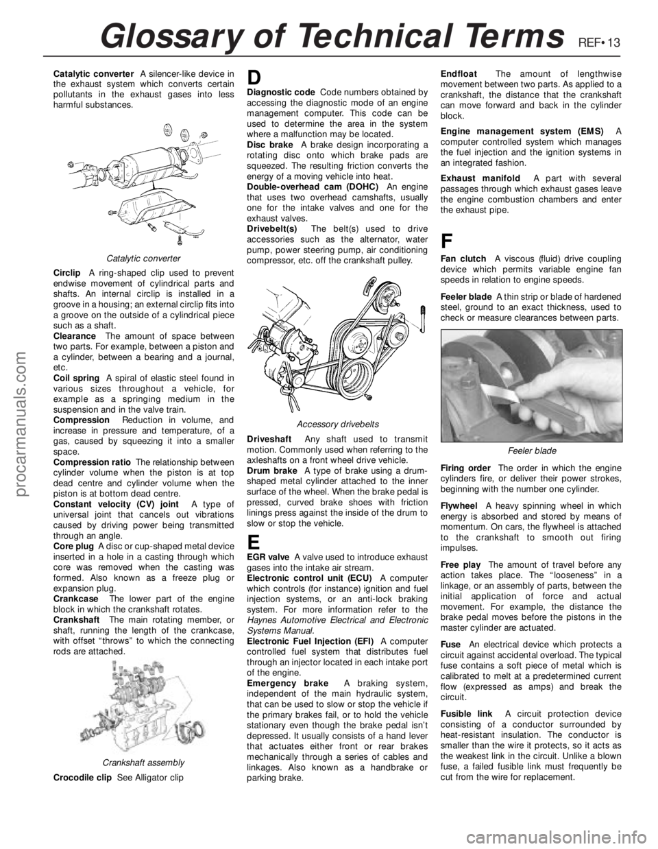
Catalytic converterA silencer-like device in
the exhaust system which converts certain
pollutants in the exhaust gases into less
harmful substances.
CirclipA ring-shaped clip used to prevent
endwise movement of cylindrical parts and
shafts. An internal circlip is installed in a
groove in a housing; an external circlip fits into
a groove on the outside of a cylindrical piece
such as a shaft.
ClearanceThe amount of space between
two parts. For example, between a piston and
a cylinder, between a bearing and a journal,
etc.
Coil springA spiral of elastic steel found in
various sizes throughout a vehicle, for
example as a springing medium in the
suspension and in the valve train.
CompressionReduction in volume, and
increase in pressure and temperature, of a
gas, caused by squeezing it into a smaller
space.
Compression ratioThe relationship between
cylinder volume when the piston is at top
dead centre and cylinder volume when the
piston is at bottom dead centre.
Constant velocity (CV) jointA type of
universal joint that cancels out vibrations
caused by driving power being transmitted
through an angle.
Core plugA disc or cup-shaped metal device
inserted in a hole in a casting through which
core was removed when the casting was
formed. Also known as a freeze plug or
expansion plug.
CrankcaseThe lower part of the engine
block in which the crankshaft rotates.
CrankshaftThe main rotating member, or
shaft, running the length of the crankcase,
with offset “throws” to which the connecting
rods are attached.
Crocodile clipSee Alligator clipDDiagnostic codeCode numbers obtained by
accessing the diagnostic mode of an engine
management computer. This code can be
used to determine the area in the system
where a malfunction may be located.
Disc brakeA brake design incorporating a
rotating disc onto which brake pads are
squeezed. The resulting friction converts the
energy of a moving vehicle into heat.
Double-overhead cam (DOHC)An engine
that uses two overhead camshafts, usually
one for the intake valves and one for the
exhaust valves.
Drivebelt(s)The belt(s) used to drive
accessories such as the alternator, water
pump, power steering pump, air conditioning
compressor, etc. off the crankshaft pulley.
DriveshaftAny shaft used to transmit
motion. Commonly used when referring to the
axleshafts on a front wheel drive vehicle.
Drum brakeA type of brake using a drum-
shaped metal cylinder attached to the inner
surface of the wheel. When the brake pedal is
pressed, curved brake shoes with friction
linings press against the inside of the drum to
slow or stop the vehicle.
EEGR valveA valve used to introduce exhaust
gases into the intake air stream.
Electronic control unit (ECU)A computer
which controls (for instance) ignition and fuel
injection systems, or an anti-lock braking
system. For more information refer to the
Haynes Automotive Electrical and Electronic
Systems Manual.
Electronic Fuel Injection (EFI)A computer
controlled fuel system that distributes fuel
through an injector located in each intake port
of the engine.
Emergency brakeA braking system,
independent of the main hydraulic system,
that can be used to slow or stop the vehicle if
the primary brakes fail, or to hold the vehicle
stationary even though the brake pedal isn’t
depressed. It usually consists of a hand lever
that actuates either front or rear brakes
mechanically through a series of cables and
linkages. Also known as a handbrake or
parking brake.EndfloatThe amount of lengthwise
movement between two parts. As applied to a
crankshaft, the distance that the crankshaft
can move forward and back in the cylinder
block.
Engine management system (EMS)A
computer controlled system which manages
the fuel injection and the ignition systems in
an integrated fashion.
Exhaust manifoldA part with several
passages through which exhaust gases leave
the engine combustion chambers and enter
the exhaust pipe.
F
Fan clutchA viscous (fluid) drive coupling
device which permits variable engine fan
speeds in relation to engine speeds.
Feeler bladeA thin strip or blade of hardened
steel, ground to an exact thickness, used to
check or measure clearances between parts.
Firing orderThe order in which the engine
cylinders fire, or deliver their power strokes,
beginning with the number one cylinder.
Flywheel A heavy spinning wheel in which
energy is absorbed and stored by means of
momentum. On cars, the flywheel is attached
to the crankshaft to smooth out firing
impulses.
Free playThe amount of travel before any
action takes place. The “looseness” in a
linkage, or an assembly of parts, between the
initial application of force and actual
movement. For example, the distance the
brake pedal moves before the pistons in the
master cylinder are actuated.
FuseAn electrical device which protects a
circuit against accidental overload. The typical
fuse contains a soft piece of metal which is
calibrated to melt at a predetermined current
flow (expressed as amps) and break the
circuit.
Fusible linkA circuit protection device
consisting of a conductor surrounded by
heat-resistant insulation. The conductor is
smaller than the wire it protects, so it acts as
the weakest link in the circuit. Unlike a blown
fuse, a failed fusible link must frequently be
cut from the wire for replacement.Catalytic converter
Crankshaft assembly
Accessory drivebelts
Feeler blade
procarmanuals.com
Page 253 of 255

IND•2
F
Facia panels and trim - 12•12
Fast idle speed adjustment - 4•13
Fault finding- REF•5et seq
Fault-finding - electrical system - 5•3, 13•3
Final drive and driveshafts- 1•15, 9•1et
seq, 11•10, REF•9
Fire - 0•5
Flasher switch and unit - 13•11
Fluid leakage - REF•8
Fluid level checks - 1•6
Flywheel ring gear - 2A•14, 2C•15
Flywheel/driveplate - 2A•9, 2A•16, 2B•15,
2C•11, 2C•17
Foglight - 13•5,13•13
Footbrake - 0•11, 0•12
Footwell lights - 13•8
Fuel and exhaust systems- 0•14, 4•1et seq,
REF•8
Fuel computer components - 13•17
Fuel consumption high - REF•8
Fuel filler lock barrel - 12•7
Fuel filler switch - 13•18
Fuel filter - 1•19, 4•14
Fuel flow sensor - 13•18
Fuel gauge gives false reading - REF•11
Fuel odour - REF•8
Fuel pressure regulator - 4•18
Fuel temperature sensor - 5•12
Fuel trap (carburettor models) - 5•9
Fume or gas intoxication - 0•5
Fumes from exhaust system - REF•8
Fuses - 13•13
G
G (gravity) switch - 10•14
Gaskets - REF•4
Gear linkage - 7A•4
Gear selection problems - REF•8, REF•9
Glossary of technical terms - REF•12
Glovebox light - 13•8
Graphic display module - 13•18
Graphic equaliser - 13•21
Grille - 12•9
H
Handbrake “ON” switch - 13•12
Handbrake - 0•11, 10•11
Handles - 12•6
Hazard warning switch - 13•9, 13•13
HC emissions - 0•14
Headlight - 13•4, 13•6, 13•7, 13•11
Headlining - 12•11
Headphone relay - 13•22
Heated rear window switch - 13•13
Heated seat control switches - 13•13
Heater assembly - 3•7, 3•8, 3•9, 3•10,
13•11, 13•20
High frequency units - 13•22
High pressure hose - 10•10
Hinges - 1•12
Horn - 13•10
Horn emits intermittent or unsatisfactory
sound - REF•11Horn fails to operate - REF•11
Horn inoperative, or unsatisfactory in
operation - REF•11
Horn operates all the time - REF•11
Horn switch plate, slip rings and brushes -
13•10
HT leads - 5•5
HT voltage - 5•3
Hub - 11•11
Hydraulic system seals and hoses - 1•19
Hydraulic unit - 10•8, 10•9, 10•10
Hydrofluoric acid - 0•5
I
Idle mixture - 1•10
Idle speed - 1•10, 4•7, 4•9, 4•11, 4•14, 5•11
Idle speed control valve - 4•15
Idle speed linkage - 1•15
Ignition coil - 5•9
Ignition module - 5•8
Ignition system - 1•17
Ignition timing - 5•7, 5•11
Ignition/no-charge warning light fails to
come on - REF•11
Ignition/no-charge warning light remains
illuminated with engine running - REF•11
Ignition/starter switch - 13•11
Inlet manifold - 1•14, 4•19
Instrument cluster - 13•9, 13•10
Instrument illumination dimmer switch - 13•11
Instrument panel lights - 13•8
Instrument readings inaccurate or erratic -
REF•11
Instruments and electrical equipment - 1•16
Intensive maintenance - 1•6
Interior lights - 13•7
Introduction to the Ford Granada - 0•4
J
Jacking - 0•6
Joint mating faces - REF•4
Joystick fader control - 13•22
Jump starting - 0•10
Jumps out of gear - REF•8
L
Latch locks but will not unlock, or unlocks
but will not lock - REF•11
Leaks - 0•8, 1•10
Lighter - 13•10
Lighting master switch - 13•11
Lights - 13•4, 13•6
Lights inoperative - REF•10
Locknuts, locktabs and washers - REF•4
Locks - 1•12, 12•6, 12•7
Loudspeakers - 13•21, 13•22
Low pressure hose - 10•10
Lower arm - 11•9, 11•12
Lubricant leaks - REF•8
Lubricants and fluids - 1•2
Luggage area light - 13•8
M
Main bearings - 2A•11, 2A•15, 2B•17,
2C•12, 2C•15
Maintenance - bodywork and underframe -
12•1
Maintenance - upholstery and carpets -
12•2
Manifold absolute pressure (MAP) sensor -
5•12
Manifold heater - 5•11
Manual gearbox- 1•11, 2B•6, 2B•7, 7A•1et
seq, REF•8
Manual steering - 11•3
Master cylinder - 10•12
Mirror - 0•11, 12•12, 13•11
Mixture adjustment potentiometer - 4•19
Mixture adjustments - 4•7, 4•9, 4•11, 4•14
Motifs and emblems - 12•10
Motor factors - 0•9
Mountings - 2A•11, 2B•8, 2C•12
N
Needle valve and float - 4•11
Number plate light - 13•5
O
Oil - 1•6, 1•9
Oil filler cap - 1•10
Oil filter - 1•9, 2A•11
Oil leakage from final drive - REF•9
Oil pressure warning light illuminated with
engine running - REF•7
Oil pressure warning switch - 13•12
Oil pump - 2A•10, 2A•12, 2A•16, 2B•16,
2B•17, 2C•11, 2C•14, 2C•17
Oil seals - 2A•10, 2B•15, 2C•12, 9•2, 9•3,
REF•4
On load voltage check - 5•5
Open-circuit - 13•3
Overcooling - REF•7
Overhead console - 12•17
Overheating - REF•7
P
Pads - 1•10, 10•4, 10•5
Parcel shelf - 12•19
Parking light - 13•4
Pedal Travel Sensor (PTS) - 10•14
Pedals - 6•2, 4•6, 10•8
Pierburg 2V carburettor - 4•7, 4•9
Pistons and connecting rods - 2A•11, 2A•13,
2A•15, 2B•17, 2C•12, 2C•14, 2C•16
Pitching and/or rolling around corners, or
during braking - REF•10
Plastic components - 12•3
Poisonous or irrirant substances - 0•5
Power steering - 1•16, 11•3, 11•4, 11•6
Power valve diaphragm - 4•12
Pre-ignition (pinking) or knocking during
acceleration or under load - REF•7
Printed circuit board - 13•20
Propeller shaft- 8•1et seq, REF•9
Pushrods - 2C•13
Index
procarmanuals.com