1985 FORD GRANADA engine overheat
[x] Cancel search: engine overheatPage 8 of 255
to release any pressure. When pressure has
been released, carry on unscrewing the cap
and remove it.
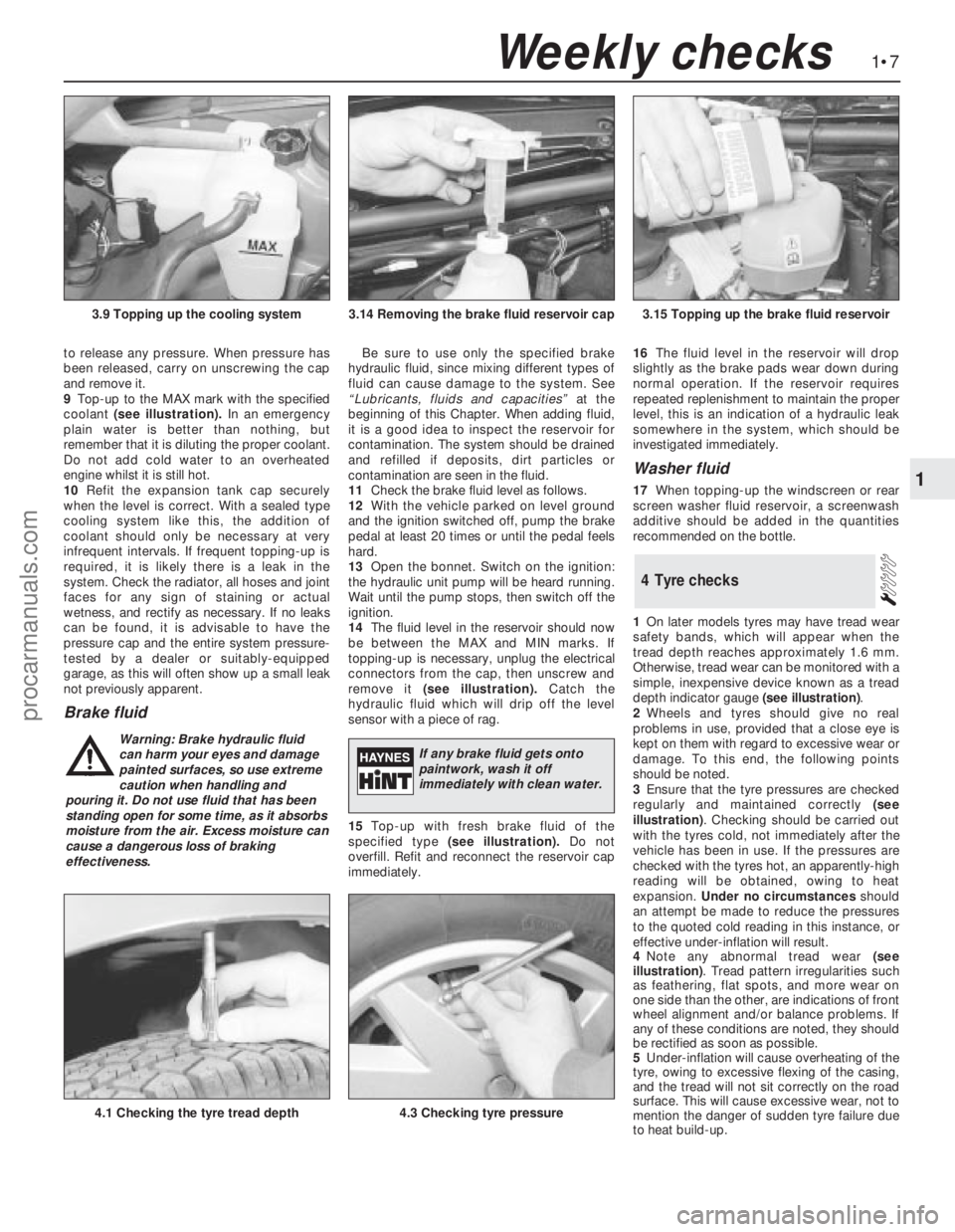
9Top-up to the MAX mark with the specified
coolant (see illustration).In an emergency
plain water is better than nothing, but
remember that it is diluting the proper coolant.
Do not add cold water to an overheated
engine whilst it is still hot.
10Refit the expansion tank cap securely
when the level is correct. With a sealed type
cooling system like this, the addition of
coolant should only be necessary at very
infrequent intervals. If frequent topping-up is
required, it is likely there is a leak in the
system. Check the radiator, all hoses and joint
faces for any sign of staining or actual
wetness, and rectify as necessary. If no leaks
can be found, it is advisable to have the
pressure cap and the entire system pressure-
tested by a dealer or suitably-equipped
garage, as this will often show up a small leak
not previously apparent.
Brake fluid
Be sure to use only the specified brake
hydraulic fluid, since mixing different types of
fluid can cause damage to the system. See
“Lubricants, fluids and capacities”at the
beginning of this Chapter. When adding fluid,
it is a good idea to inspect the reservoir for
contamination. The system should be drained
and refilled if deposits, dirt particles or
contamination are seen in the fluid.
11Check the brake fluid level as follows.
12With the vehicle parked on level ground
and the ignition switched off, pump the brake
pedal at least 20 times or until the pedal feels
hard.
13Open the bonnet. Switch on the ignition:
the hydraulic unit pump will be heard running.
Wait until the pump stops, then switch off the
ignition.
14The fluid level in the reservoir should now
be between the MAX and MIN marks. If
topping-up is necessary, unplug the electrical
connectors from the cap, then unscrew and
remove it (see illustration).Catch the
hydraulic fluid which will drip off the level
sensor with a piece of rag.
15Top-up with fresh brake fluid of the
specified type (see illustration).Do not
overfill. Refit and reconnect the reservoir cap
immediately.16The fluid level in the reservoir will drop
slightly as the brake pads wear down during
normal operation. If the reservoir requires
repeated replenishment to maintain the proper
level, this is an indication of a hydraulic leak
somewhere in the system, which should be
investigated immediately.
Washer fluid
17When topping-up the windscreen or rear
screen washer fluid reservoir, a screenwash
additive should be added in the quantities
recommended on the bottle.
1On later models tyres may have tread wear
safety bands, which will appear when the
tread depth reaches approximately 1.6 mm.
Otherwise, tread wear can be monitored with a
simple, inexpensive device known as a tread
depth indicator gauge (see illustration).
2Wheels and tyres should give no real
problems in use, provided that a close eye is
kept on them with regard to excessive wear or
damage. To this end, the following points
should be noted.
3Ensure that the tyre pressures are checked
regularly and maintained correctly (see
illustration). Checking should be carried out
with the tyres cold, not immediately after the
vehicle has been in use. If the pressures are
checked with the tyres hot, an apparently-high
reading will be obtained, owing to heat
expansion. Under no circumstancesshould
an attempt be made to reduce the pressures
to the quoted cold reading in this instance, or
effective under-inflation will result.
4Note any abnormal tread wear (see
illustration). Tread pattern irregularities such
as feathering, flat spots, and more wear on
one side than the other, are indications of front
wheel alignment and/or balance problems. If
any of these conditions are noted, they should
be rectified as soon as possible.
5Under-inflation will cause overheating of the
tyre, owing to excessive flexing of the casing,
and the tread will not sit correctly on the road
surface. This will cause excessive wear, not to
mention the danger of sudden tyre failure due
to heat build-up.
4Tyre checks
1•7
1
Weekly checks
3.14 Removing the brake fluid reservoir cap3.15 Topping up the brake fluid reservoir
4.1 Checking the tyre tread depth4.3 Checking tyre pressure
3.9 Topping up the cooling system
Warning: Brake hydraulic fluid
can harm your eyes and damage
painted surfaces, so use extreme
caution when handling and
pouring it. Do not use fluid that has been
standing open for some time, as it absorbs
moisture from the air. Excess moisture can
cause a dangerous loss of braking
effectiveness.If any brake fluid gets onto
paintwork, wash it off
immediately with clean water.
procarmanuals.com
Page 37 of 255
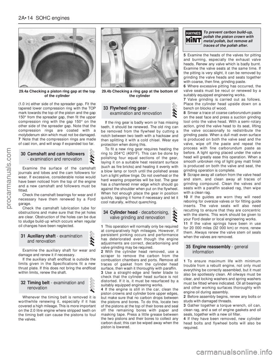
(1.0 in) either side of the spreader gap. Fit the
tapered lower compression ring with the TOP
mark towards the top of the piston and the gap
150°from the spreader gap, then fit the upper
compression ring with the gap 150°on the
other side of the spreader gap. Note that the
compression rings are coated with a
molybdenum skin which must not be damaged.
7Note that the compression rings are made
of cast iron, and will snap if expanded too far.
Examine the surface of the camshaft
journals and lobes and the cam followers for
wear. If excessive, considerable noise would
have been noticed from the top of the engine
and a new camshaft and followers must be
fitted.
Check the camshaft bearings for wear and if
necessary have them renewed by a Ford
garage.
Check the camshaft lubrication tube for
obstructions and make sure that the jet holes
are clear. Obstruction of the holes can be due
to sludge build-up which occurs when regular
oil changes have been neglected.
Examine the auxiliary shaft for wear and
damage and renew it if necessary.
If the auxiliary shaft endfloat is outside the
limits given in the Specifications fit a new
thrust plate. If this does not bring the endfloat
within limits, renew the shaft.
Whenever the timing belt is removed it is
worthwhile renewing it, especially if it has
covered a high mileage. This is more important
on the 2.0 litre engine where stripped teeth on
the timing belt can cause the pistons to foul
the valves.If the ring gear is badly worn or has missing
teeth, it should be renewed. The old ring can
be removed from the flywheel by cutting a
notch between two teeth with a hacksaw and
then splitting it with a cold chisel. Wear eye
protection when doing this.
To fit a new ring gear requires heating the
ring to 204°C (400°F). This can be done by
polishing four equal sections of the gear,
laying it on a suitable heat resistant surface
(such as fire bricks) and heating it evenly with
a blow lamp or torch until the polished areas
turn a light yellow tinge. Do not overheat or the
hard wearing properties will be lost. The gear
has a chamfered inner edge which should go
against the shoulder when put on the flywheel.
When hot enough place the gear in position
quickly, tapping it home if necessary and let it
cool naturally, without quenching.
1This operation will normally only be required
at comparatively high mileages. However, if
persistent pinking occurs and performance
has deteriorated even though the engine
adjustments are correct, decarbonising and
valve grinding may be required.
2With the cylinder head removed, use a
scraper to remove the carbon from the
combustion chambers and ports. Remove all
traces of gasket from the cylinder head
surface, then wash it thoroughly with paraffin.
3Use a straight-edge and feeler blade to
check that the cylinder head surface is not
distorted. If it is, it must be resurfaced by a
suitably equipped engineering works.
4If the engine is still in the car, clean the
piston crowns and cylinder bore upper edges,
but make sure that no carbon drops between
the pistons and bores. To do this, locate two
of the pistons at the top of their bores and seal
off the remaining bores with paper and
masking tape. Press a little grease between
the two pistons and their bores to collect any
carbon dust; this can be wiped away when the
piston is lowered.5Examine the heads of the valves for pitting
and burning, especially the exhaust valve
heads. Renew any valve which is badly burnt.
Examine the valve seats at the same time. If
the pitting is very slight, it can be removed by
grinding the valve heads and seats together
with coarse, then fine, grinding paste.
6Where excessive pitting has occurred, the
valve seats must be recut or renewed by a
suitably equipped engineering works.
7Valve grinding is carried out as follows.
Place the cylinder head upside down on a
bench on blocks of wood.
8Smear a trace of coarse carborundum paste
on the seat face and press a suction grinding
tool onto the valve head. With a semi-rotary
action, grind the valve head to its seat, lifting
the valve occasionally to redistribute the
grinding paste. When a dull matt even surface
is produced on both the valve seat and the
valve, wipe off the paste and repeat the
process with fine carborundum paste as
before. A light spring placed under the valve
head will greatly ease this operation. When a
smooth unbroken ring of light grey matt finish
is produced on both the valve and seat, the
grinding operation is complete.
9Scrape away all carbon from the valve head
and stem, and clean away all traces of
grinding compound. Clean the valves and
seats with a paraffin soaked rag, then wipe
with a clean rag.
10If the guides are worn they will need
reboring for oversize valves or for fitting guide
inserts. The valve seats will also need
recutting to ensure that they are concentric
with the stems. This work should be given to
your Ford dealer or local engineering works.
11If the valve springs have been in use
for 20 000 miles (32 000 km) or more, renew
them. Always renew the valve stem oil seals
when the valves are removed.
1To ensure maximum life with minimum
trouble from a rebuilt engine, not only must
everything be correctly assembled, but it must
also be spotlessly clean. All oilways must be
clear, and locking washers and spring washers
must be fitted where indicated. Oil all bearings
and other working surfaces thoroughly with
engine oil during assembly.
2Before assembly begins, renew any bolts or
studs with damaged threads.
3Gather together a torque wrench, oil can,
clean rag, and a set of engine gaskets and oil
seals, together with a new oil filter.
4If they have been removed, new cylinder
head bolts and flywheel bolts will also be
required.
35Engine reassembly - general
information
34Cylinder head - decarbonising,
valve grinding and renovation
33Flywheel ring gear -
examination and renovation
32Timing belt - examination and
renovation
31Auxiliary shaft - examination
and renovation
30Camshaft and cam followers
- examination and renovation
2A•14SOHCengines
29.4a Checking a piston ring gap at the top
of the cylinder29.4b Checking a ring gap at the bottom of
the cylinder
To prevent carbon build-up,
polish the piston crown with
metal polish, but remove all
traces of the polish after.
procarmanuals.com
Page 97 of 255
The exhaust system fitted in production is
made of aluminised steel, with stainless steel
used in the endplates and baffles of the rear
silencer. Individual sections of the system are
easily renewed in service.
Emission control for the UK market is
achieved largely by the inherent efficiency of
the fuel, ignition and engine management
systems. A welcome spin-off from such
efficiency is remarkably good fuel economy for
a vehicle of such size and weight.
Precautions
Fuel
Many of the procedures in this Chapter
require the removal of fuel lines and
connections which may result in some fuel
spillage. Residual pressure in fuel-injection
systems will remain in the fuel lines long after
the vehicle was last used, therefore extra care
must be taken when disconnecting a fuel line
hose. Loosen any fuel hose slowly to avoid a
sudden release of pressure which may cause
fuel spray. As an added precaution place a rag
over each union as it is disconnected to catch
any fuel which is forcibly expelled. Before
carrying out any operation on the fuel system
refer to the precautions given in “Safety first!”
at the beginning of this Manual and follow
them implicitly. Petrol is a highly dangerous
and volatile liquid and the precautions
necessary when handling it cannot be
overstressed
Tamperproof adjustment screws
Certain adjustment points in the fuel system
(and elsewhere) are protected by tamperproof
caps, plugs or seals. The purpose of such
tamperproofing is to discourage, and to deter,
adjustment by unqualified operators.
In some EU countries (though not yet in the
UK) it is an offence to drive a vehicle with
missing or broken tamperproof seals. Before
disturbing a tamperproof seal, satisfy yourself
that you will not be breaking local or national
anti-pollution regulations by doing so. Fit a
new seal when adjustment is complete when
this is required by law.
Do not break tamperproof seals on a vehicle
which is still under warranty.
Catalytic converter
The catalytic converter is a reliable and
simple device which needs no maintenance in
itself, but there are some facts of which an
owner should be aware if the converter is to
function properly for the full service life.
a)DO NOT use leaded petrol in a car
equipped with a catalytic converter the
lead will coat the precious metals,
reducing their converting efficiency and
will eventually destroy the converter.
b)Always keep the ignition and fuel systems
well-maintained in accordance with the
manufacturer’s schedule - particularly,
ensure that the air cleaner filter element,
the fuel filter and the spark plugs are
renewed at the correct interval - if the inletair/fuel mixture is allowed to become too
rich due to neglect, the unburned surplus
will enter and burn in the catalytic
converter, overheating the element and
eventually destroying the converter.
c)If the engine develops a misfire, do not
drive the car at all (or at least as little as
possible) until the fault is cured - the
misfire will allow unburned fuel to enter
the converter, which will result in
overheating, as noted above.
d)DO NOT push- or tow-start the car - this
will soak the catalytic converter in
unburned fuel, causing it to overheat when
the engine does start - see b) above.
e)DO NOT switch off the ignition at high
engine speeds - if the ignition is switched
off at anything above idle speed,
unburnedfuel will enter the (very hot)
catalytic converter, with the possible risk
of igniting on the element and damaging
the converter.
f)DO NOT use fuel or engine oil additives -
these may contain substances harmful to
the catalytic converter.
g)DO NOT continue to use the car if the
engine burns oil to the extent of leaving a
visible trail of blue smoke - the unburned
carbon deposits will clog the converter
passages and reduce the efficiency; in
severe cases the element will overheat.
h)Remember that the catalytic converter
operates at very high temperatures -
hence the heat shields on the car’s
underbody and the casing will become hot
enough to ignite combustible materials
which brush against it - DO NOT,
therefore, park the car in dry undergrowth,
over long grass or piles of dead leaves.
i)Remember that the catalytic converter is
FRAGILE, do not strike it with tools during
servicing work, take great care when
working on the exhaust system, ensure
that the converter is well clear of any jacks
or other lifting gear used to raise the car
and do not drive the car over rough
ground, road humps, etc, in such a way as
to “ground” the exhaust system.
j)In some cases, particularly when the car is
new and/or is used for stop/start driving, a
sulphurous smell (like that of rotten eggs)may be noticed from the exhaust. This is
common to many catalytic converter-
equipped cars and seems to be due to the
small amount of sulphur found in some
petrols reacting with hydrogen in the
exhaust to produce hydrogen sulphide
(H
2S) gas; while this gas is toxic, it is not
produced in sufficient amounts to be a
problem. Once the car has covered a few
thousand miles the problem should
disappear - in the meanwhile a change of
driving style or of the brand of petrol used
may effect a solution.
k)The catalytic converter, used on a well-
maintained and well-driven car, should
last for between 50 000 and 100 000 miles
- from this point on, careful checks should
be made at all specified service intervals
of the CO level to ensure that the
converter is still operating efficiently - if
the converter is no longer effective it must
be renewed.
See Chapter 1, Section 38.
1On carburettor models only, the air cleaner
can take in both hot and cold air. Hot air is
obtained from a shroud bolted to the exhaust
manifold.
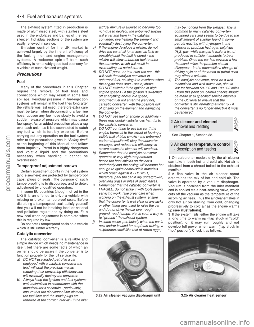
2A flap valve in the air cleaner spout
determines the mix of hot and cold air. The
valve is operated by a vacuum diaphragm.
Vacuum is obtained from the inlet manifold
and is applied via a heat-sensing valve, which
cuts off the vacuum as the temperature of the
incoming air rises. Thus the air cleaner takes in
only hot air on starting from cold, changing
progressively to cold air as the engine warms
up (see illustrations).
3If the system fails, either the engine will take
a long time to warm up (flap stuck in “cold”
position), or it may run roughly and not
develop full power when warm (flap stuck in
“hot” position). Check it as follows.
3Air cleaner temperature control
- description and testing
2Air cleaner and element -
removal and refitting
4•4Fuel and exhaust systems
3.2b Air cleaner heat sensor3.2a Air cleaner vacuum diaphragm unit
procarmanuals.com
Page 120 of 255
engine coolant temperature sensor. The
crankshaft speed/position sensor is activated
by a toothed disc on the rear of the crankshaft,
inside the cylinder block. The disc has 35
equally spaced teeth (one every 10°), with a
gap in the 36th position. The gap is used by
the sensor to determine the crankshaft
position relative to Top Dead Centre (TDC) of
No 1 piston.
The ignition advance is a function of the
ESC II module, and is controlled by vacuum.
The module is connected to the carburettor by
a vacuum pipe, and a transducer in the
module translates the vacuum signal into an
electrical voltage. From the vacuum signal, the
module determines engine load; engine speed
and temperature are determined from the
crankshaft speed/position sensor and the
engine coolant temperature sensor. The
module has a range of spark advance settings
stored in the memory, and a suitable setting is
selected for the relevant engine speed, load
and temperature. The degree of advance can
thus be constantly varied to suit the prevailing
engine speed and load conditions.
On DOHC fuel-injected engines, a
development of the EEC IV (Electronic Engine
Control IV) engine management system is
used to control both the ignition and fuel-
injection systems. The EEC IV module receives
information from a crankshaft speed/position
sensor (the same as that fitted to the
carburettor models), a throttle position sensor,
an engine coolant temperature sensor, a fuel
temperature sensor, an air charge temperature
sensor, a Manifold Absolute Pressure (MAP)
sensor, and a vehicle speed sensor (mounted
on the gearbox). Additionally, on models with
a catalytic converter, an additional input is
supplied to the EEC IV module from an
exhaust gas oxygen (HEGO) sensor. On
models with automatic transmission,
additional sensors are fitted to the
transmission to inform the EEC IV module
when the transmission is in neutral, and when
the downshift is being operated.
The module provides outputs to control the
fuel pump, fuel-injectors, idle speed, ignition
system and automatic transmission .
Additionally, on models with air conditioning,
the EEC IV module disengages the air
conditioning compressor clutch when starting
the engine or when the engine is suddenly
accelerated. On models fitted with a catalytic
converter, the EEC IV module also controls the
carbon canister purge solenoid valve.
Using the inputs from the various sensors,
the EEC IV module computes the optimum
ignition advance, and fuel-injector pulse
duration to suit the prevailing engine
conditions.
On 2.4 & 2.9 litre V6 engines, the system
operates in much the same way as that fitted
to the DOHC fuel-injected engine, noting the
following points.
a)There is no crankshaft speed/position
sensor.
b)The vehicle speed sensor is only fitted to
models equipped with a catalytic
converter.Precautions
ESC II module
Although it will tolerate all normal under-
bonnet conditions, the ESC II module may be
adversely affected by water entry during
steam cleaning or pressure washing of the
engine bay.
If cleaning the engine bay, therefore, take
care not to direct jets of water or steam at the
ESC II module. If this cannot be avoided,
remove the module completely, and protect its
multi-plug with a plastic bag.
Ignition system HT voltage
Take care to avoid receiving electric shocks
from the HT side of the ignition system. Do not
handle HT leads, or touch the distributor or
coil, when the engine is running. When tracing
faults in the HT system, use well insulated
tools to manipulate live leads. Electronic
ignition HT voltage could prove fatal.
Electronic ignition systems
General
Further details of the various systems are
given in the relevant Sections of this Chapter.
While some repair procedures are given, the
usual course of action is to renew the
component concerned. The owner whose
interest extends beyond mere component
renewal should obtain a copy of the
Automobile Electrical & Electronic Systems
Manual, available from the publishers of this
manual.
It is necessary to take extra care when
working on the electrical system, to avoid
damage to semi-conductor devices (diodes
and transistors), and to avoid the risk of
personal injury. In addition to the precautions
given in Safety first!at the beginning of this
manual, observe the following when working
on the system:
Always remove rings, watches, etc before
working on the electrical system.Even with the
battery disconnected, capacitive discharge
could occur if a component’s live terminal is
earthed through a metal object. This could
cause a shock or nasty burn.
Do not reverse the battery connections.
Components such as the alternator, electronic
control units, or any other components having
semi-conductor circuitry, could be irreparably
damaged.
If the engine is being started using jump
leads and a slave battery, connect thebatteries positive-to-positiveand negative-to-
negative(see “Jump starting”). This also
applies when connecting a battery charger.
Never disconnect the battery terminals, the
alternator, any electrical wiring, or any test
instruments, when the engine is running.
Do not allow the engine to turn the alternator
when the alternator is not connected.
Never test for alternator output by “flashing”
the output lead to earth.
Never use an ohmmeter of the type
incorporating a hand-cranked generator for
circuit or continuity testing.
Always ensure that the battery negative lead
is disconnected when working on the
electrical system.
Before using electric-arc welding equipment
on the car, disconnect the battery, alternator,
and components such as the fuel-
injection/ignition electronic control unit, to
protect them from the risk of damage.
Refer to Chapter 13
1In normal use the battery should not require
charging from an external source, unless the
vehicle is laid up for long periods, when it
should be recharged every six weeks or so. If
vehicle use consists entirely of short runs in
darkness it is also possible for the battery to
become discharged. Otherwise, a regular
need for recharging points to a fault in the
battery or elsewhere in the charging system.
2There is no need to disconnect the battery
from the vehicle wiring when using a battery
charger, but switch off the ignition and leave
the bonnet open.
3Domestic battery chargers (up to about 6
amps output) may safely be used overnight
without special precautions. Make sure that
the charger is set to deliver 12 volts before
connecting it. Connect the leads (red or
positive to the positive terminal, black or
negative to the negative terminal) before
switching the charger on at the mains.
4When charging is complete, switch off at
the mains beforedisconnecting the charger
from the battery. Remember that the battery
will be giving off hydrogen gas, which is
potentially explosive.
5Charging at a higher rate should only be
carried out under carefully controlled
conditions. Very rapid or “boost” charging
should be avoided if possible, as it is liable to
cause permanent damage to the battery
through overheating.
6During any sort of charging, battery
electrolyte temperature should never exceed
38°C (100°F). If the battery becomes hot, or
the electrolyte is effervescing vigorously,
charging should be stopped.
3Battery - charging
2Electrical fault-finding - general
information
Engine electrical systems 5•3
5
Warning. The voltages produced
by the electronic ignition system
are considerably higher than those
produced by conventional
systems. Extreme care must be taken when
working on the system with the ignition
switched on. Persons with surgically-
implanted cardiac pacemaker devices
should keep well clear of the ignition
circuits, components and test equipment.
procarmanuals.com
Page 121 of 255
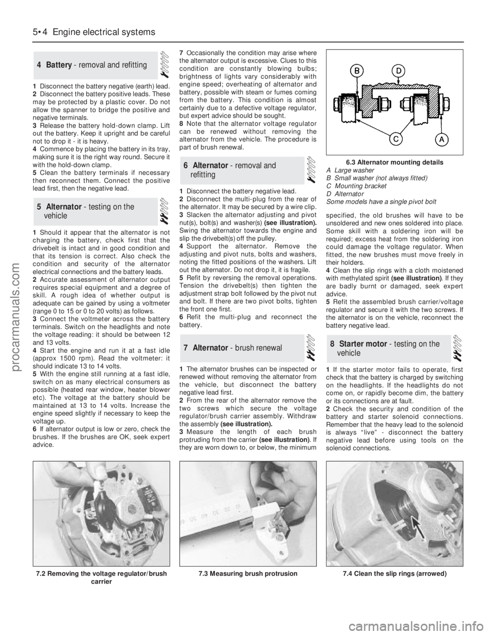
1Disconnect the battery negative (earth) lead.
2Disconnect the battery positive leads. These
may be protected by a plastic cover. Do not
allow the spanner to bridge the positive and
negative terminals.
3Release the battery hold-down clamp. Lift
out the battery. Keep it upright and be careful
not to drop it - it is heavy.
4Commence by placing the battery in its tray,
making sure it is the right way round. Secure it
with the hold-down clamp.
5Clean the battery terminals if necessary
then reconnect them. Connect the positive
lead first, then the negative lead.
1Should it appear that the alternator is not
charging the battery, check first that the
drivebelt is intact and in good condition and
that its tension is correct. Also check the
condition and security of the alternator
electrical connections and the battery leads.
2Accurate assessment of alternator output
requires special equipment and a degree of
skill. A rough idea of whether output is
adequate can be gained by using a voltmeter
(range 0 to 15 or 0 to 20 volts) as follows.
3Connect the voltmeter across the battery
terminals. Switch on the headlights and note
the voltage reading: it should be between 12
and 13 volts.
4Start the engine and run it at a fast idle
(approx 1500 rpm). Read the voltmeter: it
should indicate 13 to 14 volts.
5With the engine still running at a fast idle,
switch on as many electrical consumers as
possible (heated rear window, heater blower
etc). The voltage at the battery should be
maintained at 13 to 14 volts. Increase the
engine speed slightly if necessary to keep the
voltage up.
6If alternator output is low or zero, check the
brushes. If the brushes are OK, seek expert
advice.7Occasionally the condition may arise where
the alternator output is excessive. Clues to this
condition are constantly blowing bulbs;
brightness of lights vary considerably with
engine speed; overheating of alternator and
battery, possible with steam or fumes coming
from the battery. This condition is almost
certainly due to a defective voltage regulator,
but expert advice should be sought.
8Note that the alternator voltage regulator
can be renewed without removing the
alternator from the vehicle. The procedure is
part of brush renewal.
1Disconnect the battery negative lead.
2Disconnect the multi-plug from the rear of
the alternator. It may be secured by a wire clip.
3Slacken the alternator adjusting and pivot
nut(s), bolt(s)and washer(s)(see illustration).
Swing the alternator towards the engine and
slip the drivebelt(s) off the pulley.
4Support the alternator. Remove the
adjusting and pivot nuts, bolts and washers,
noting the fitted positions of the washers. Lift
out the alternator. Do not drop it, it is fragile.
5Refit by reversing the removal operations.
Tension the drivebelt(s) then tighten the
adjustment strap bolt followed by the pivot nut
and bolt. If there are two pivot bolts, tighten
the front one first.
6Refit the multi-plug and reconnect the
battery.
1The alternator brushes can be inspected or
renewed without removing the alternator from
the vehicle, but disconnect the battery
negative lead first.
2From the rear of the alternator remove the
two screws which secure the voltage
regulator/brush carrier assembly. Withdraw
the assembly (see illustration).
3Measure the length of each brush
protruding from the carrier (see illustration). If
they are worn down to, or below, the minimumspecified, the old brushes will have to be
unsoldered and new ones soldered into place.
Some skill with a soldering iron will be
required; excess heat from the soldering iron
could damage the voltage regulator. When
fitted, the new brushes must move freely in
their holders.
4Clean the slip rings with a cloth moistened
with methylated spirit (see illustration). If they
are badly burnt or damaged, seek expert
advice.
5Refit the assembled brush carrier/voltage
regulator and secure it with the two screws. If
the alternator is on the vehicle, reconnect the
battery negative lead.
1If the starter motor fails to operate, first
check that the battery is charged by switching
on the headlights. If the headlights do not
come on, or rapidly become dim, the battery
or its connections are at fault.
2Check the security and condition of the
battery and starter solenoid connections.
Remember that the heavy lead to the solenoid
is always “live” - disconnect the battery
negative lead before using tools on the
solenoid connections.
8Starter motor - testing on the
vehicle7Alternator - brush renewal
6Alternator - removal and
refitting
5Alternator - testing on the
vehicle
4Battery - removal and refitting
5•4Engine electrical systems
7.3 Measuring brush protrusion7.4 Clean the slip rings (arrowed)
6.3 Alternator mounting details
A Large washer
B Small washer (not always fitted)
C Mounting bracket
D Alternator
Some models have a single pivot bolt
7.2 Removing the voltage regulator/brush
carrier
procarmanuals.com
Page 240 of 255
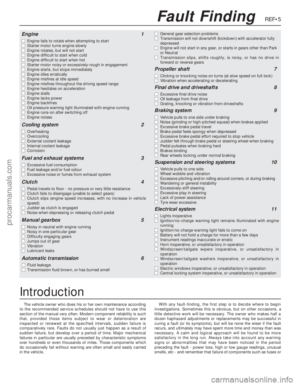
The vehicle owner who does his or her own maintenance according
to the recommended service schedules should not have to use this
section of the manual very often. Modern component reliability is such
that, provided those items subject to wear or deterioration are
inspected or renewed at the specified intervals, sudden failure is
comparatively rare. Faults do not usually just happen as a result of
sudden failure, but develop over a period of time. Major mechanical
failures in particular are usually preceded by characteristic symptoms
over hundreds or even thousands of miles. Those components which
do occasionally fail without warning are often small and easily carried
in the vehicle.With any fault-finding, the first step is to decide where to begin
investigations. Sometimes this is obvious, but on other occasions, a
little detective work will be necessary. The owner who makes half a
dozen haphazard adjustments or replacements may be successful in
curing a fault (or its symptoms), but will be none the wiser if the fault
recurs, and ultimately may have spent more time and money than was
necessary. A calm and logical approach will be found to be more
satisfactory in the long run. Always take into account any warning
signs or abnormalities that may have been noticed in the period
preceding the fault - power loss, high or low gauge readings, unusual
smells, etc - and remember that failure of components such as fuses or
REF•5Fault Finding
Engine1
m mEngine fails to rotate when attempting to start
m mStarter motor turns engine slowly
m mEngine rotates, but will not start
m mEngine difficult to start when cold
m mEngine difficult to start when hot
m mStarter motor noisy or excessively-rough in engagement
m mEngine starts, but stops immediately
m mEngine idles erratically
m mEngine misfires at idle speed
m mEngine misfires throughout the driving speed range
m mEngine hesitates on acceleration
m mEngine stalls
m mEngine lacks power
m mEngine backfires
m mOil pressure warning light illuminated with engine running
m mEngine runs-on after switching off
m mEngine noises
Cooling system2
m
mOverheating
m mOvercooling
m mExternal coolant leakage
m mInternal coolant leakage
m mCorrosion
Fuel and exhaust systems3
m
mExcessive fuel consumption
m mFuel leakage and/or fuel odour
m mExcessive noise or fumes from exhaust system
Clutch4
m
mPedal travels to floor - no pressure or very little resistance
m mClutch fails to disengage (unable to select gears)
m mClutch slips (engine speed increases, with no increase in vehicle
speed)
m mJudder as clutch is engaged
m mNoise when depressing or releasing clutch pedal
Manual gearbox5
m
mNoisy in neutral with engine running
m mNoisy in one particular gear
m mDifficulty engaging gears
m mJumps out of gear
m mVibration
m mLubricant leaks
Automatic transmission6
m
mFluid leakage
m mTransmission fluid brown, or has burned smellm mGeneral gear selection problems
m mTransmission will not downshift (kickdown) with accelerator fully
depressed
m mEngine will not start in any gear, or starts in gears other than Park
or Neutral
m mTransmission slips, shifts roughly, is noisy, or has no drive in
forward or reverse gears
Propeller shaft7
m
mClicking or knocking noise on turns (at slow speed on full-lock)
m mVibration when accelerating or decelerating
Final drive and driveshafts8
m
mExcessive final drive noise
m mOil leakage from final drive
m mGrating, knocking or vibration from driveshafts
Braking system9
m
mVehicle pulls to one side under braking
m mNoise (grinding or high-pitched squeal) when brakes applied
m mExcessive brake pedal travel
m mBrake pedal feels spongy when depressed
m mExcessive brake pedal effort required to stop vehicle
m mJudder felt through brake pedal or steering wheel when braking
m mPedal pulsates when braking hard
m mBrakes binding
m mRear wheels locking under normal braking
Suspension and steering systems10
m
mVehicle pulls to one side
m mWheel wobble and vibration
m mExcessive pitching and/or rolling around corners, or during braking
m mWandering or general instability
m mExcessively-stiff steering
m mExcessive play in steering
m mLack of power assistance
m mTyre wear excessive
Electrical system11
m
mLights inoperative
m mIgnition/no-charge warning light remains illuminated with engine
running
m mIgnition/no-charge warning light fails to come on
m mBattery will not hold a charge for more than a few days
m mInstrument readings inaccurate or erratic
m mHorn inoperative, or unsatisfactory in operation
m mWindscreen/tailgate wipers inoperative, or unsatisfactory in
operation
m mWindscreen/tailgate washers inoperative, or unsatisfactory in
operation
m mElectric windows inoperative, or unsatisfactory in operation
m mCentral locking system inoperative, or unsatisfactory in operation
Introduction
procarmanuals.com
Page 242 of 255
Engine misfires throughout the driving speed range
m mFuel filter choked (Chapter 1).
m mFuel pump faulty, or delivery pressure low (Chapter 4).
m mFuel tank vent blocked, or fuel pipes restricted (Chapter 4).
m mVacuum leak at the throttle body, inlet manifold or associated hoses
(Chapter 4).
m mWorn, faulty or incorrectly-gapped spark plugs (Chapter 1).
m mFaulty spark plug HT leads (Chapter 5).
m mDistributor cap cracked or tracking internally (Chapter 5).
m mFaulty ignition coil (Chapter 5).
m mUneven or low cylinder compressions (Chapter 2).
m mFuel injection system fault (Chapter 4).
Engine hesitates on acceleration
m
mWorn, faulty or incorrectly-gapped spark plugs (Chapter 1).
m mVacuum leak at the throttle body, inlet manifold or associated hoses
(Chapter 4).
m mFuel injection system fault (Chapter 4).
Engine stalls
m
mVacuum leak at the throttle body, inlet manifold or associated hoses
(Chapter 4).
m mFuel filter choked (Chapter 1).
m mFuel pump faulty, or delivery pressure low (Chapter 4).
m mFuel tank vent blocked, or fuel pipes restricted (Chapter 4).
m mFuel injection system fault (Chapter 4).
Engine lacks power
m
mFuel filter choked (Chapter 1).
m mFuel pump faulty, or delivery pressure low (Chapter 4).
m mUneven or low cylinder compressions (Chapter 2).
m mWorn, faulty or incorrectly-gapped spark plugs (Chapter 1).
m mVacuum leak at the throttle body, inlet manifold or associated hoses
(Chapter 4).
m mFuel injection system fault (Chapter 4).
m mBrakes binding (Chapters 1 and 10).
m mClutch slipping (Chapter 6).
Engine backfires
m
mVacuum leak at the throttle body, inlet manifold or associated hoses
(Chapter 4).
m mFuel injection system fault (Chapter 4).
Oil pressure warning light illuminated with engine
running
m mLow oil level, or incorrect oil grade (Chapter 1).
m mFaulty oil pressure sensor (Chapter 2).
m mWorn engine bearings and/or oil pump (Chapter 2).
m mExcessively high engine operating temperature (Chapter 3).
m mOil pressure relief valve defective (Chapter 2).
m mOil pick-up strainer clogged (Chapter 2).
Note:Low oil pressure in a high-mileage engine at tickover is not
necessarily a cause for concern. Sudden pressure loss at speed is far
more significant. In any event, check the gauge or warning light sender
before condemning the engine.
Engine runs-on after switching off
m mExcessive carbon build-up in engine (Chapter 2).
m mExcessively high engine operating temperature (Chapter 3).
Engine noises
Pre-ignition (pinking) or knocking during acceleration or
under load
m mIgnition timing incorrect/ignition system fault (Chapters 1 and 5).
m mIncorrect grade of spark plug (Chapter 1).
m mIncorrect grade of fuel (Chapter 1).
m mVacuum leak at throttle body, inlet manifold or associated hoses
(Chapter 4).
m mExcessive carbon build-up in engine (Chapter 2).
m mFuel injection system fault (Chapter 4).
Whistling or wheezing noises
m
mLeaking inlet manifold or throttle body gasket (Chapter 4).
m mLeaking exhaust manifold gasket (Chapter 4).
m mLeaking vacuum hose (Chapters 4 and 10).
m mBlowing cylinder head gasket (Chapter 2).
Tapping or rattling noises
m
mWorn valve gear, timing chain, camshaft or hydraulic tappets
(Chapter 2).
m mAncillary component fault (water pump, alternator, etc) (Chapters 3,
5, etc).
Knocking or thumping noises
m mWorn big-end bearings (regular heavy knocking, perhaps less under
load) (Chapter 2).
m mWorn main bearings (rumbling and knocking, perhaps worsening
under load) (Chapter 2).
m mPiston slap (most noticeable when cold) (Chapter 2).
m mAncillary component fault (water pump, alternator, etc) (Chapters 3,
5, etc).
REF•7Fault Finding
2Cooling system
Overheating
m
mAuxiliary drivebelt broken or incorrectly adjusted (Chapter 1).
m mInsufficient coolant in system (Chapter 1).
m mThermostat faulty (Chapter 3).
m mRadiator core blocked, or grille restricted (Chapter 3).
m mElectric cooling fan or thermostatic switch faulty (Chapter 3).
m mViscous-coupled fan faulty (Chapter 3).
m mIgnition timing incorrect, or ignition system fault (Chapters 1 and 5).
m mInaccurate temperature gauge sender unit (Chapter 3).
m mAirlock in cooling system (Chapter 3).
Overcooling
m
mThermostat faulty (Chapter 3).
m mInaccurate temperature gauge sender unit (Chapter 3).
External coolant leakage
m
mDeteriorated or damaged hoses or hose clips (Chapter 1).
m mRadiator core or heater matrix leaking (Chapter 3).
m mPressure cap faulty (Chapter 3).
m mWater pump internal seal leaking (Chapter 3).
m mWater pump-to-block seal leaking (Chapter 3).
m mBoiling due to overheating (Chapter 3).
m mCore plug leaking (Chapter 2).
Internal coolant leakage
m
mLeaking cylinder head gasket (Chapter 2).
m mCracked cylinder head or cylinder block (Chapter 2).
Corrosion
m
mInfrequent draining and flushing (Chapter 1).
m mIncorrect coolant mixture or inappropriate coolant type (Chapter 1).
procarmanuals.com
Page 253 of 255
IND•2
F
Facia panels and trim - 12•12
Fast idle speed adjustment - 4•13
Fault finding- REF•5et seq
Fault-finding - electrical system - 5•3, 13•3
Final drive and driveshafts- 1•15, 9•1et
seq, 11•10, REF•9
Fire - 0•5
Flasher switch and unit - 13•11
Fluid leakage - REF•8
Fluid level checks - 1•6
Flywheel ring gear - 2A•14, 2C•15
Flywheel/driveplate - 2A•9, 2A•16, 2B•15,
2C•11, 2C•17
Foglight - 13•5,13•13
Footbrake - 0•11, 0•12
Footwell lights - 13•8
Fuel and exhaust systems- 0•14, 4•1et seq,
REF•8
Fuel computer components - 13•17
Fuel consumption high - REF•8
Fuel filler lock barrel - 12•7
Fuel filler switch - 13•18
Fuel filter - 1•19, 4•14
Fuel flow sensor - 13•18
Fuel gauge gives false reading - REF•11
Fuel odour - REF•8
Fuel pressure regulator - 4•18
Fuel temperature sensor - 5•12
Fuel trap (carburettor models) - 5•9
Fume or gas intoxication - 0•5
Fumes from exhaust system - REF•8
Fuses - 13•13
G
G (gravity) switch - 10•14
Gaskets - REF•4
Gear linkage - 7A•4
Gear selection problems - REF•8, REF•9
Glossary of technical terms - REF•12
Glovebox light - 13•8
Graphic display module - 13•18
Graphic equaliser - 13•21
Grille - 12•9
H
Handbrake “ON” switch - 13•12
Handbrake - 0•11, 10•11
Handles - 12•6
Hazard warning switch - 13•9, 13•13
HC emissions - 0•14
Headlight - 13•4, 13•6, 13•7, 13•11
Headlining - 12•11
Headphone relay - 13•22
Heated rear window switch - 13•13
Heated seat control switches - 13•13
Heater assembly - 3•7, 3•8, 3•9, 3•10,
13•11, 13•20
High frequency units - 13•22
High pressure hose - 10•10
Hinges - 1•12
Horn - 13•10
Horn emits intermittent or unsatisfactory
sound - REF•11Horn fails to operate - REF•11
Horn inoperative, or unsatisfactory in
operation - REF•11
Horn operates all the time - REF•11
Horn switch plate, slip rings and brushes -
13•10
HT leads - 5•5
HT voltage - 5•3
Hub - 11•11
Hydraulic system seals and hoses - 1•19
Hydraulic unit - 10•8, 10•9, 10•10
Hydrofluoric acid - 0•5
I
Idle mixture - 1•10
Idle speed - 1•10, 4•7, 4•9, 4•11, 4•14, 5•11
Idle speed control valve - 4•15
Idle speed linkage - 1•15
Ignition coil - 5•9
Ignition module - 5•8
Ignition system - 1•17
Ignition timing - 5•7, 5•11
Ignition/no-charge warning light fails to
come on - REF•11
Ignition/no-charge warning light remains
illuminated with engine running - REF•11
Ignition/starter switch - 13•11
Inlet manifold - 1•14, 4•19
Instrument cluster - 13•9, 13•10
Instrument illumination dimmer switch - 13•11
Instrument panel lights - 13•8
Instrument readings inaccurate or erratic -
REF•11
Instruments and electrical equipment - 1•16
Intensive maintenance - 1•6
Interior lights - 13•7
Introduction to the Ford Granada - 0•4
J
Jacking - 0•6
Joint mating faces - REF•4
Joystick fader control - 13•22
Jump starting - 0•10
Jumps out of gear - REF•8
L
Latch locks but will not unlock, or unlocks
but will not lock - REF•11
Leaks - 0•8, 1•10
Lighter - 13•10
Lighting master switch - 13•11
Lights - 13•4, 13•6
Lights inoperative - REF•10
Locknuts, locktabs and washers - REF•4
Locks - 1•12, 12•6, 12•7
Loudspeakers - 13•21, 13•22
Low pressure hose - 10•10
Lower arm - 11•9, 11•12
Lubricant leaks - REF•8
Lubricants and fluids - 1•2
Luggage area light - 13•8
M
Main bearings - 2A•11, 2A•15, 2B•17,
2C•12, 2C•15
Maintenance - bodywork and underframe -
12•1
Maintenance - upholstery and carpets -
12•2
Manifold absolute pressure (MAP) sensor -
5•12
Manifold heater - 5•11
Manual gearbox- 1•11, 2B•6, 2B•7, 7A•1et
seq, REF•8
Manual steering - 11•3
Master cylinder - 10•12
Mirror - 0•11, 12•12, 13•11
Mixture adjustment potentiometer - 4•19
Mixture adjustments - 4•7, 4•9, 4•11, 4•14
Motifs and emblems - 12•10
Motor factors - 0•9
Mountings - 2A•11, 2B•8, 2C•12
N
Needle valve and float - 4•11
Number plate light - 13•5
O
Oil - 1•6, 1•9
Oil filler cap - 1•10
Oil filter - 1•9, 2A•11
Oil leakage from final drive - REF•9
Oil pressure warning light illuminated with
engine running - REF•7
Oil pressure warning switch - 13•12
Oil pump - 2A•10, 2A•12, 2A•16, 2B•16,
2B•17, 2C•11, 2C•14, 2C•17
Oil seals - 2A•10, 2B•15, 2C•12, 9•2, 9•3,
REF•4
On load voltage check - 5•5
Open-circuit - 13•3
Overcooling - REF•7
Overhead console - 12•17
Overheating - REF•7
P
Pads - 1•10, 10•4, 10•5
Parcel shelf - 12•19
Parking light - 13•4
Pedal Travel Sensor (PTS) - 10•14
Pedals - 6•2, 4•6, 10•8
Pierburg 2V carburettor - 4•7, 4•9
Pistons and connecting rods - 2A•11, 2A•13,
2A•15, 2B•17, 2C•12, 2C•14, 2C•16
Pitching and/or rolling around corners, or
during braking - REF•10
Plastic components - 12•3
Poisonous or irrirant substances - 0•5
Power steering - 1•16, 11•3, 11•4, 11•6
Power valve diaphragm - 4•12
Pre-ignition (pinking) or knocking during
acceleration or under load - REF•7
Printed circuit board - 13•20
Propeller shaft- 8•1et seq, REF•9
Pushrods - 2C•13
Index
procarmanuals.com