1985 FORD GRANADA key battery
[x] Cancel search: key batteryPage 19 of 255
distributor cap, making a sketch if necessary
so that they can be reconnected to the same
terminals. Remove the leads.
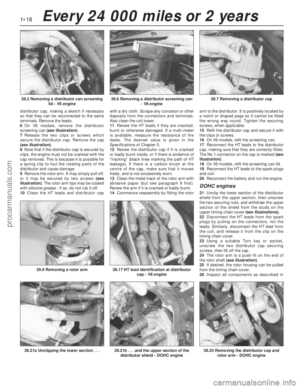
6On V6 models, remove the distributor
screening can (see illustration).
7Release the two clips or screws which
secure the distributor cap. Remove the cap
(see illustration).
8Note that if the distributor cap is secured by
clips, the engine must not be cranked with the
cap removed. This is because it is possible for
a spring clip to foul the rotating parts of the
distributor and cause damage.
9Remove the rotor arm. It may simply pull off,
or it may be secured by two screws (see
illustration). The rotor arm tips may be coated
with silicone grease - if so, do not rub it off.
10Clean the HT leads and distributor capwith a dry cloth. Scrape any corrosion or other
deposits from the connectors and terminals.
Also clean the coil tower.
11Renew the HT leads if they are cracked,
burnt or otherwise damaged. If a multi-meter
is available, measure the resistance of the
leads. The desired value is given in the
Specifications of Chapter 5.
12Renew the distributor cap if it is cracked
or badly burnt inside, or if there is evidence of
“tracking” (black lines marking the path of HT
leakage). If there is a carbon brush at the
centre of the cap, make sure that it moves
freely, and is not excessively worn.
13Clean the metal track of the rotor arm with
abrasive paper (but see paragraph 9 first).
Renew the arm if it is cracked or badly burnt.
14Commence reassembly by fitting the rotorarm to the distributor. It is positively located by
a notch or shaped pegs so it cannot be fitted
the wrong way round. Tighten the securing
screws, when applicable.
15Refit the distributor cap and secure it with
the clips or screws.
16On V6 models, refit the screening can.
17Reconnect the HT leads to the distributor
cap, making sure that they are correctly fitted.
The No 1 connector on the cap is marked (see
illustration).
18On V6 models, refit the screening can lid.
19Reconnect the HT leads to the spark plugs
and coil.
20Reconnect the battery and run the engine.
DOHC engines
21Unclip the lower section of the distributor
shield from the upper section, then unscrew
the two securing nuts, and withdraw the upper
section of the shield from the studs on the
upper timing chain cover (see illustrations).
22Disconnect the HT leads from the spark
plugs by pulling on the connectors, not the
leads. Similarly, disconnect the HT lead from
the coil, and release it from the clip on the
timing chain cover.
23Using a suitable Torx key or socket,
unscrew the two distributor cap securing
screws, then lift off the cap.
24The rotor arm is a push-fit on the end of
the rotor shaft (see illustration).
25If desired, the rotor housing can be pulled
from the timing chain cover.
26Inspect all components as described in
1•18Every 24 000 miles or 2 years
39.6 Removing a distributor screening can
- V6 engine39.7 Removing a distributor cap39.3 Removing a distributor can screening
lid - V6 engine
39.21b . . . and the upper section of the
distributor shield - DOHC engine39.24 Removing the distributor cap and
rotor arm - DOHC engine39.21a Unclipping the lower section . . .
39.9 Removing a rotor arm39.17 HT lead identification at distributor
cap - V6 engine
procarmanuals.com
Page 29 of 255
14Take the weight of the engine and remove
the two engine bearer-to-mounting nuts.
15Lift the engine/transmission, at the same
time lowering the trolley jack. Draw the unit
forwards and lift it out of the engine bay.
16Temporarily refit the anti-roll bar if the
vehicle is to be moved.
1With the engine and gearbox on the bench,
remove the starter motor.
2Remove the bolt from the engine adapter plate.
3Remove the bracing strap and the
remaining engine-to-bellhousing bolts.
4With the aid of an assistant draw the
gearbox off the engine. Do not allow the weight
of the gearbox to hang on the input shaft.
1It is best to mount the engine on a
dismantling stand, but if this is not available,
stand the engine on a strong bench at a
comfortable working height. Failing this, it will
have to be stripped down on the floor.
2Cleanliness is most important, and if the
engine is dirty, it should be cleaned with
paraffin while keeping it in an upright position.
3Avoid working with the engine on a concrete
floor, as grit can be a real source of trouble.
4As parts are removed, clean them in paraffin.
However, do not immerse parts with internal
oilways in paraffin as it is difficult to remove,
usually requiring a high pressure hose.
5It is advisable to have suitable containers to
hold small items according to their use, as this
will help when reassembling the engine and
also prevent possible losses.
6Always obtain complete sets of gaskets
when the engine is being dismantled, but
retain the old gaskets with a view of using
them as a pattern to make a replacement if a
new one is not available.7When possible, refit nuts, bolts and washers
in their location after being removed, as this
helps protect the threads and will also be
helpful when reassembling the engine.
8Retain unserviceable components in order
to compare them with the new parts supplied.
9A Torx key, size T55, will be needed for
dealing with the cylinder head bolts. A 12-
spline key (to fit bolt size M8) will be needed
for the oil pump bolts. Other Torx and 12-
spline bolts may be encountered; sets of the
keys required to deal with them are available
from most motor accessory shops and tool
factors.
10Another tool which is useful, though by no
means essential, is a valve spring compressor
of the type which hooks under the camshaft
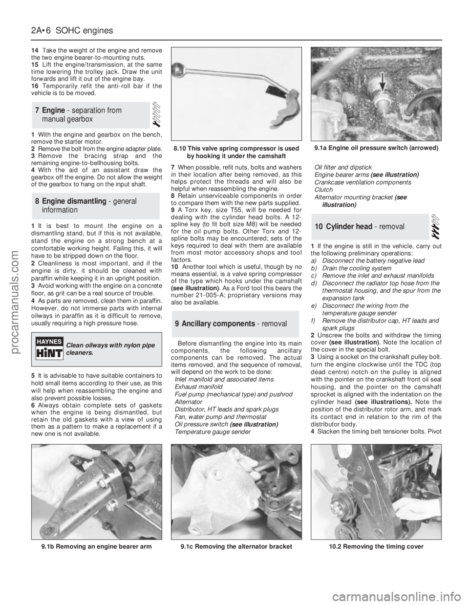
(see illustration). As a Ford tool this bears the
number 21-005-A; proprietary versions may
also be available.
Before dismantling the engine into its main
components, the following ancillary
components can be removed. The actual
items removed, and the sequence of removal,
will depend on the work to be done:
Inlet manifold and associated items
Exhaust manifold
Fuel pump (mechanical type) and pushrod
Alternator
Distributor, HT leads and spark plugs
Fan, water pump and thermostat
Oil pressure switch
(see illustration)
Temperature gauge senderOil filter and dipstick
Engine bearer arms (see illustration)
Crankcase ventilation components
Clutch
Alternator mounting bracket (see
illustration)
1If the engine is still in the vehicle, carry out
the following preliminary operations:
a)Disconnect the battery negative lead
b)Drain the cooling system
c)Remove the inlet and exhaust manifolds
d)Disconnect the radiator top hose from the
thermostat housing, and the spur from the
expansion tank
e)Disconnect the wiring from the
temperature gauge sender
f)Remove the distributor cap, HT leads and
spark plugs
2Unscrew the bolts and withdraw the timing
cover (see illustration). Note the location of
the cover in the special bolt.
3Using a socket on the crankshaft pulley bolt.
turn the engine clockwise until the TDC (top
dead centre) notch on the pulley is aligned
with the pointer on the crankshaft front oil seal
housing, and the pointer on the camshaft
sprocket is aligned with the indentation on the
cylinder head (see illustrations).Note the
position of the distributor rotor arm, and mark
its contact end in relation to the rim of the
distributor body.
4Slacken the timing belt tensioner bolts. Pivot
10Cylinder head - removal
9Ancillary components - removal
8Engine dismantling - general
information
7Engine - separation from
manual gearbox
2A•6SOHCengines
9.1a Engine oil pressure switch (arrowed)
9.1b Removing an engine bearer arm9.1c Removing the alternator bracket
8.10 This valve spring compressor is used
by hooking it under the camshaft
Clean oilways with nylon pipe
cleaners.
10.2 Removing the timing cover
procarmanuals.com
Page 53 of 255
prevent the chain from dropping into the
timing case, as during removal.
18Locate the double chain sprocket loosely
over the end of the crankshaft (larger sprocket
nearest the crankcase), with the timing mark
pointing vertically down.
19Fit the chain over the inner, larger
sprocket, aligning the coppered link in the
chain with the timing mark on the sprocket
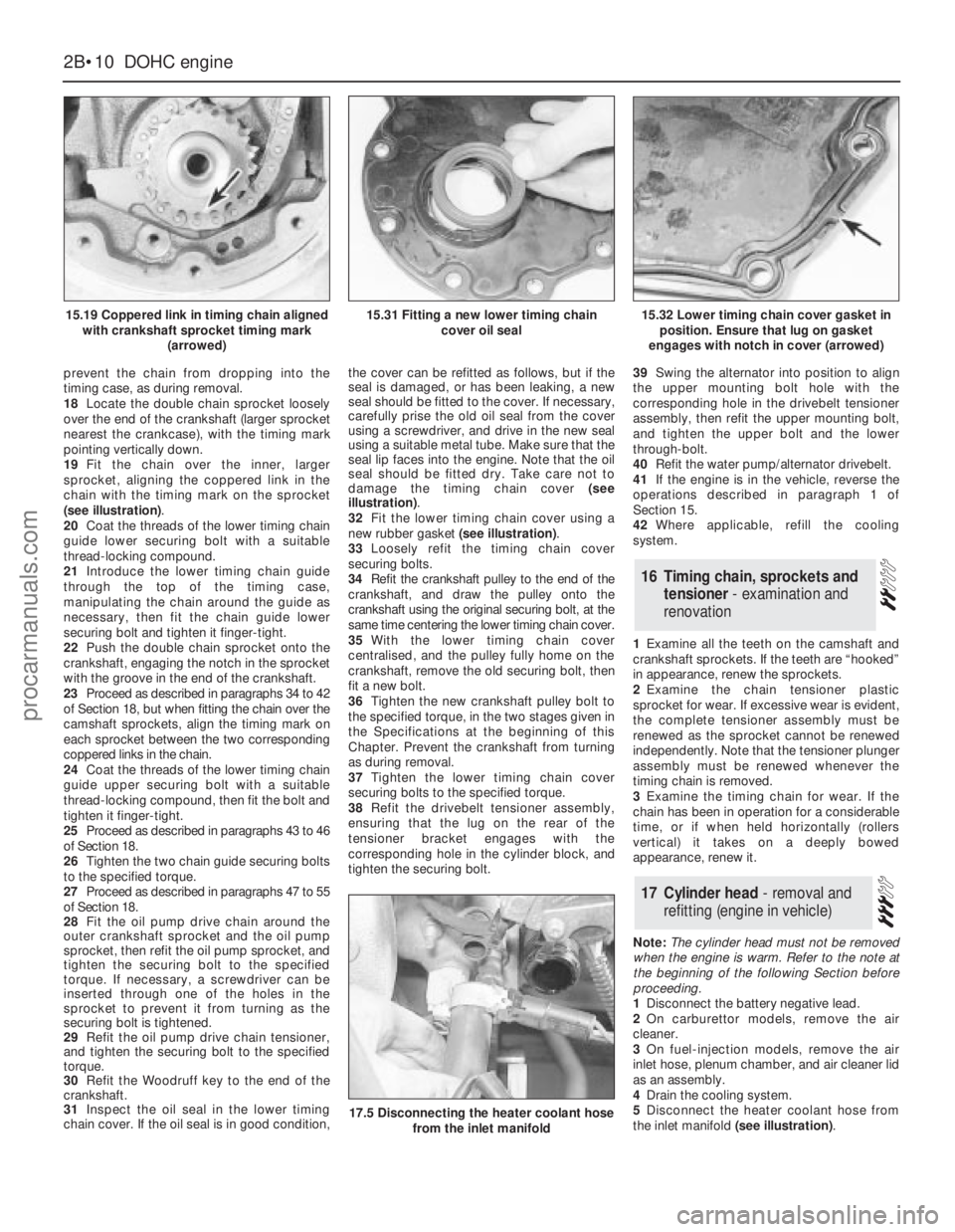
(see illustration).
20Coat the threads of the lower timing chain
guide lower securing bolt with a suitable
thread-locking compound.
21Introduce the lower timing chain guide
through the top of the timing case,
manipulating the chain around the guide as
necessary, then fit the chain guide lower
securing bolt and tighten it finger-tight.
22Push the double chain sprocket onto the
crankshaft, engaging the notch in the sprocket
with the groove in the end of the crankshaft.
23Proceed as described in paragraphs 34 to 42
of Section 18, but when fitting the chain over the
camshaft sprockets, align the timing mark on
each sprocket between the two corresponding
coppered links in the chain.
24Coat the threads of the lower timing chain
guide upper securing bolt with a suitable
thread-locking compound, then fit the bolt and
tighten it finger-tight.
25Proceed as described in paragraphs 43 to 46
of Section 18.
26Tighten the two chain guide securing bolts
to the specified torque.
27Proceed as described in paragraphs 47 to 55
of Section 18.
28Fit the oil pump drive chain around the
outer crankshaft sprocket and the oil pump
sprocket, then refit the oil pump sprocket, and
tighten the securing bolt to the specified
torque. If necessary, a screwdriver can be
inserted through one of the holes in the
sprocket to prevent it from turning as the
securing bolt is tightened.
29Refit the oil pump drive chain tensioner,
and tighten the securing bolt to the specified
torque.
30Refit the Woodruff key to the end of the
crankshaft.
31Inspect the oil seal in the lower timing
chain cover. If the oil seal is in good condition,the cover can be refitted as follows, but if the
seal is damaged, or has been leaking, a new
seal should be fitted to the cover. If necessary,
carefully prise the old oil seal from the cover
using a screwdriver, and drive in the new seal
using a suitable metal tube. Make sure that the
seal lip faces into the engine. Note that the oil
seal should be fitted dry. Take care not to
damage the timing chain cover (see
illustration).
32Fit the lower timing chain cover using a
new rubber gasket (see illustration).
33Loosely refit the timing chain cover
securing bolts.
34Refit the crankshaft pulley to the end of the
crankshaft, and draw the pulley onto the
crankshaft using the original securing bolt, at the
same time centering the lower timing chain cover.
35With the lower timing chain cover
centralised, and the pulley fully home on the
crankshaft, remove the old securing bolt, then
fit a new bolt.
36Tighten the new crankshaft pulley bolt to
the specified torque, in the two stages given in
the Specifications at the beginning of this
Chapter. Prevent the crankshaft from turning
as during removal.
37Tighten the lower timing chain cover
securing bolts to the specified torque.
38Refit the drivebelt tensioner assembly,
ensuring that the lug on the rear of the
tensioner bracket engages with the
corresponding hole in the cylinder block, and
tighten the securing bolt.39Swing the alternator into position to align
the upper mounting bolt hole with the
corresponding hole in the drivebelt tensioner
assembly, then refit the upper mounting bolt,
and tighten the upper bolt and the lower
through-bolt.
40Refit the water pump/alternator drivebelt.
41If the engine is in the vehicle, reverse the
operations described in paragraph 1 of
Section 15.
42Where applicable, refill the cooling
system.
1Examine all the teeth on the camshaft and
crankshaft sprockets. If the teeth are “hooked”
in appearance, renew the sprockets.
2Examine the chain tensioner plastic
sprocket for wear. If excessive wear is evident,
the complete tensioner assembly must be
renewed as the sprocket cannot be renewed
independently.Note that the tensioner plunger
assembly must be renewed whenever the
timing chain is removed.
3Examine the timing chain for wear. If the
chain has been in operation for a considerable
time, or if when held horizontally (rollers
vertical) it takes on a deeply bowed
appearance, renew it.
Note: The cylinder head must not be removed
when the engine is warm. Refer to the note at
the beginning of the following Section before
proceeding.
1Disconnect the battery negative lead.
2On carburettor models, remove the air
cleaner.
3On fuel-injection models, remove the air
inlet hose, plenum chamber, and air cleaner lid
as an assembly.
4Drain the cooling system.
5Disconnect the heater coolant hose from
the inlet manifold (see illustration).
17Cylinder head - removal and
refitting (engine in vehicle)
16Timing chain, sprockets and
tensioner - examination and
renovation
2B•10DOHCengine
15.19 Coppered link in timing chain aligned
with crankshaft sprocket timing mark
(arrowed)
17.5 Disconnecting the heater coolant hose
from the inlet manifold
15.31 Fitting a new lower timing chain
cover oil seal15.32 Lower timing chain cover gasket in
position. Ensure that lug on gasket
engages with notch in cover (arrowed)
procarmanuals.com
Page 69 of 255
Other items
34Disconnect the throttle cable from the
operating lever and bracket.
35Disconnect the right-hand exhaust
downpipe from the manifold then remove the
starter motor, the oil filter, and disconnect the
left-hand exhaust downpipe, in that order.
Refer to Part A, Section 8, paragraphs 1 to 8
of this Chapter.
Cylinder head bolts on the V6 engine may
be conventional (hexagon-headed) or Torx
type. The appropriate Torx key will be needed
to deal with the latter.
Before dismantling the engine into its main
components, the following ancillaries can be
removed. The actual items removed, and the
sequence of removal, will depend on the work
to be done.
Distributor and bracket
Spark plugs
Inlet manifold and associated items
Exhaust manifolds
Clutch
Alternator and bracket
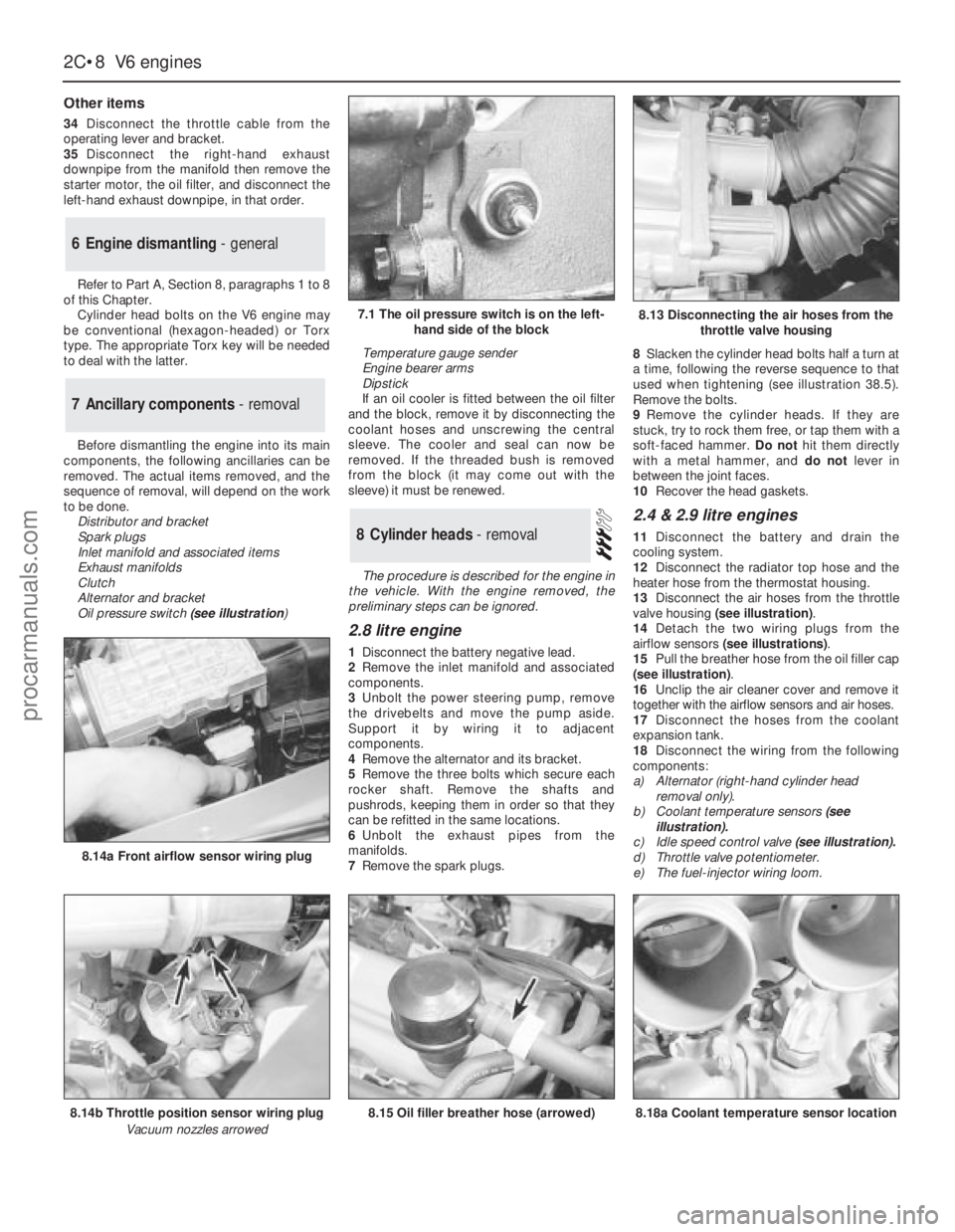
Oil pressure switch(see illustration) Temperature gauge sender
Engine bearer arms
Dipstick
If an oil cooler is fitted between the oil filter
and the block, remove it by disconnecting the
coolant hoses and unscrewing the central
sleeve. The cooler and seal can now be
removed. If the threaded bush is removed
from the block (it may come out with the
sleeve) it must be renewed.
The procedure is described for the engine in
the vehicle. With the engine removed, the
preliminary steps can be ignored.
2.8 litre engine
1Disconnect the battery negative lead.
2Remove the inlet manifold and associated
components.
3Unbolt the power steering pump, remove
the drivebelts and move the pump aside.
Support it by wiring it to adjacent
components.
4Remove the alternator and its bracket.
5Remove the three bolts which secure each
rocker shaft. Remove the shafts and
pushrods, keeping them in order so that they
can be refitted in the same locations.
6Unbolt the exhaust pipes from the
manifolds.
7Remove the spark plugs.8Slacken the cylinder head bolts half a turn at
a time, following the reverse sequence to that
used when tightening (see illustration 38.5).
Remove the bolts.
9Remove the cylinder heads. If they are
stuck, try to rock them free, or tap them with a
soft-faced hammer. Do nothit them directly
with a metal hammer, and do notlever in
between the joint faces.
10Recover the head gaskets.
2.4 & 2.9 litre engines
11Disconnect the battery and drain the
cooling system.
12Disconnect the radiator top hose and the
heater hose from the thermostat housing.
13Disconnect the air hoses from the throttle
valve housing (see illustration).
14Detach the two wiring plugs from the
airflow sensors (see illustrations).
15Pull the breather hose from the oil filler cap
(see illustration).
16Unclip the air cleaner cover and remove it
together with the airflow sensors and air hoses.
17Disconnect the hoses from the coolant
expansion tank.
18Disconnect the wiring from the following
components:
a)Alternator (right-hand cylinder head
removal only).
b)Coolant temperature sensors(see
illustration).
c)Idle speed control valve (see illustration).
d)Throttle valve potentiometer.
e)The fuel-injector wiring loom.8Cylinder heads - removal
7Ancillary components - removal
6Engine dismantling - general
2C•8V6 engines
7.1 The oil pressure switch is on the left-
hand side of the block
8.14b Throttle position sensor wiring plug
Vacuum nozzles arrowed
8.14a Front airflow sensor wiring plug
8.15 Oil filler breather hose (arrowed)8.18a Coolant temperature sensor location
8.13 Disconnecting the air hoses from the
throttle valve housing
procarmanuals.com
Page 71 of 255
4Remove the auxiliary drivebelts.
5Remove the fan and viscous clutch if fitted).
6Jam the crankshaft, either by engaging 5th
gear and applying the handbrake, or by
removing the starter motor and having an
assistant jam a screwdriver in the starter ring
gear teeth. Unbolt the crankshaft pulley. When
the pulley is secured to a vibration damper,
also remove the damper central bolt.
7Remove the pulley or damper, using a puller
if necessary.
8Disconnect the coolant hoses from the front
of the engine, including the water pump
bypass hose.
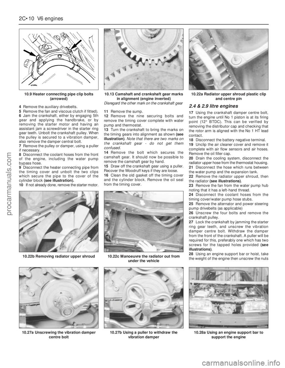
9Disconnect the heater connecting pipe from
the timing cover and unbolt the two clips
which secure the pipe to the cover of the
cylinder block (see illustration).
10If not already done, remove the starter motor.11Remove the sump.
12Remove the nine securing bolts and
remove the timing cover complete with water
pump and thermostat.
13Turn the crankshaft to bring the marks on
the timing gears into alignment as shown (see
illustration). Note that there are two marks on
the crankshaft gear - do not get them
confused.
14Remove the bolt which secures the
camshaft gear. It should now be possible to
remove the camshaft gear by hand.
15Draw off the crankshaft gear using a puller.
Recover the Woodruff keys if they are loose.
16Clean the old gasket off the timing cover
and the cylinder block. Remove the oil seal
from the timing cover.2.4 & 2.9 litre engines
17Using the crankshaft damper centre bolt,
turn the engine until No 1 piston is at its firing
point (12°BTDC). This can be verified by
removing the distributor cap and checking that
the rotor arm is aligned with the No 1 HT lead
contact.
18Disconnect the battery negative terminal.
19Unclip the air cleaner cover and remove it
complete with air flow sensors and air hoses.
Remove the oil filler cap.
20Drain the cooling system, disconnect the
radiator upper hose from the thermostat housing.
21Disconnect the hose which runs between
the water pump and the expansion tank.
22Remove the radiator upper shroud, then
the radiator (see illustrations).
23Remove the fan from the water pump hub
noting that it has a left-hand thread.
24Disconnect the coolant hoses from the
timing cover/water pump hose stubs.
25Remove the alternator and power steering
pump drivebelts (as applicable)
26Unscrew the four bolts and remove the
crankshaft pulley.
27Lock the crankshaft by jamming the starter
ring gear teeth, and unscrew the vibration
damper centre bolt. Withdraw the damper
from the front of the crankshaft. A puller will be
required for this, preferably one which has two
screws for the tapped holes provided (see
illustrations).
28Using an engine support bar or hoist, take
the weight of the engine then unscrew the nuts
2C•10V6 engines
10.9 Heater connecting pipe clip bolts
(arrowed)
10.27a Unscrewing the vibration damper
centre bolt
10.22b Removing radiator upper shroud10.22c Manoeuvre the radiator out from
under the vehicle
10.27b Using a puller to withdraw the
vibration damper10.28a Using an engine support bar to
support the engine
10.13 Camshaft and crankshaft gear marks
in alignment (engine inverted)
Disregard the other mark on the crankshaft gear10.22a Radiator upper shroud plastic clip
and centre pin
procarmanuals.com
Page 80 of 255
29Fit the sump and the retaining nuts and
bolts. Tighten them progressively in two stages.
30Oil the lip of the timing cover oil seal and
the contact surface of the crankshaft damper.
31Fit the damper to the crankshaft, being
careful not to dislodge the Woodruff key. Draw
the damper into position using the retaining
bolt and washer.
32Remove the bolt and apply sealant to the
faces of the washer. Refit the bolt and washer
then jam the starter gear ring teeth and tighten
the bolt to the specified torque.
33Refit the crankshaft pulley and tighten the
retaining bolts to the specified torque.
34Refit the crossmember side brackets and
brake pipes.
35Reconnect the engine mountings and
remove the engine hoist or axle stands (see
“Jacking”).36Connect the steering shaft coupling with
the steering wheel and front roadwheels in the
straight-ahead position. Fit the pinch-bolt and
tighten it to the specified torque.
37Fit the starter motor and connect the leads.
38Bolt the coolant distributor pipe to the
timing cover.
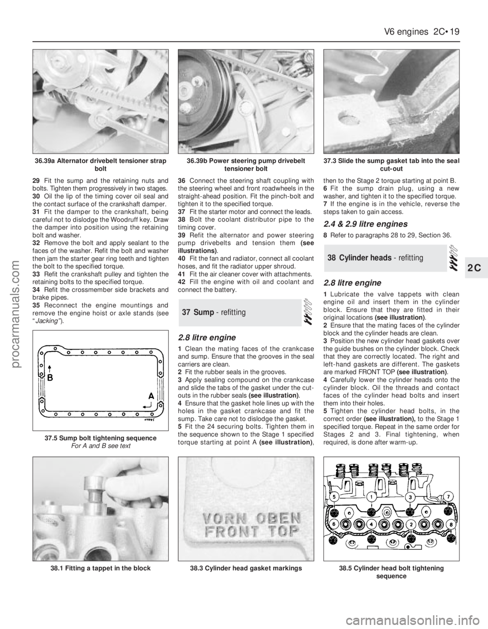
39Refit the alternator and power steering
pump drivebelts and tension them (see
illustrations).
40Fit the fan and radiator, connect all coolant
hoses, and fit the radiator upper shroud.
41Fit the air cleaner cover with attachments.
42Fill the engine with oil and coolant and
connect the battery.
2.8 litre engine
1Clean the mating faces of the crankcase
and sump. Ensure that the grooves in the seal
carriers are clean.
2Fit the rubber seals in the grooves.
3Apply sealing compound on the crankcase
and slide the tabs of the gasket under the cut-
outs in the rubber seals (see illustration).
4Ensure that the gasket hole lines up with the
holes in the gasket crankcase and fit the
sump. Take care not to dislodge the gasket.
5Fit the 24 securing bolts. Tighten them in
the sequence shown to the Stage 1 specified
torque starting at point A (see illustration),then to the Stage 2 torque starting at point B.
6Fit the sump drain plug, using a new
washer, and tighten it to the specified torque.
7If the engine is in the vehicle, reverse the
steps taken to gain access.
2.4 & 2.9 litre engines
8Refer to paragraphs 28 to 29, Section 36.
2.8 litre engine
1Lubricate the valve tappets with clean
engine oil and insert them in the cylinder
block. Ensure that they are fitted in their
original locations (see illustration).
2Ensure that the mating faces of the cylinder
block and the cylinder heads are clean.
3Position the new cylinder head gaskets over
the guide bushes on the cylinder block. Check
that they are correctly located. The right and
left-hand gaskets are different. The gaskets
are marked FRONT TOP (see illustration).
4Carefully lower the cylinder heads onto the
cylinder block. Oil the threads and contact
faces of the cylinder head bolts and insert
them into their holes.
5Tighten the cylinder head bolts, in the
correct order(see illustration),to the Stage 1
specified torque. Repeat in the same order for
Stages 2 and 3. Final tightening, when
required, is done after warm-up.
38Cylinder heads - refitting
37Sump - refitting
V6 engines 2C•19
2C
36.39a Alternator drivebelt tensioner strap
bolt36.39b Power steering pump drivebelt
tensioner bolt37.3 Slide the sump gasket tab into the seal
cut-out
38.1 Fitting a tappet in the block
37.5 Sump bolt tightening sequence
For A and B see text
38.3 Cylinder head gasket markings38.5 Cylinder head bolt tightening
sequence
procarmanuals.com
Page 99 of 255
25To remove the pump, first remove the fuel
tank.
26Unscrew the fuel pump/fuel level sender
unit by engaging two crossed screwdrivers in
the slots on either side of the unit mounting
flange. Recover the seal.
27Refitting is a reversal of removal. It is
necessary to fit a new seal.
1Run the fuel level as low as possible before
removing the tank.
2Disconnect the battery negative lead.
3Remove the fuel filler cap. Siphon or pump
the remaining fuel out of the tank. Store the
fuel in a suitable sealed container.
4Remove the two screws on either side of the
filler neck.
5Raise and support the rear of the vehicle.
6Remove the shield from the right-hand rear
inner wheel arch. Also remove the rear bumper
undershield. which is secured by six screws.
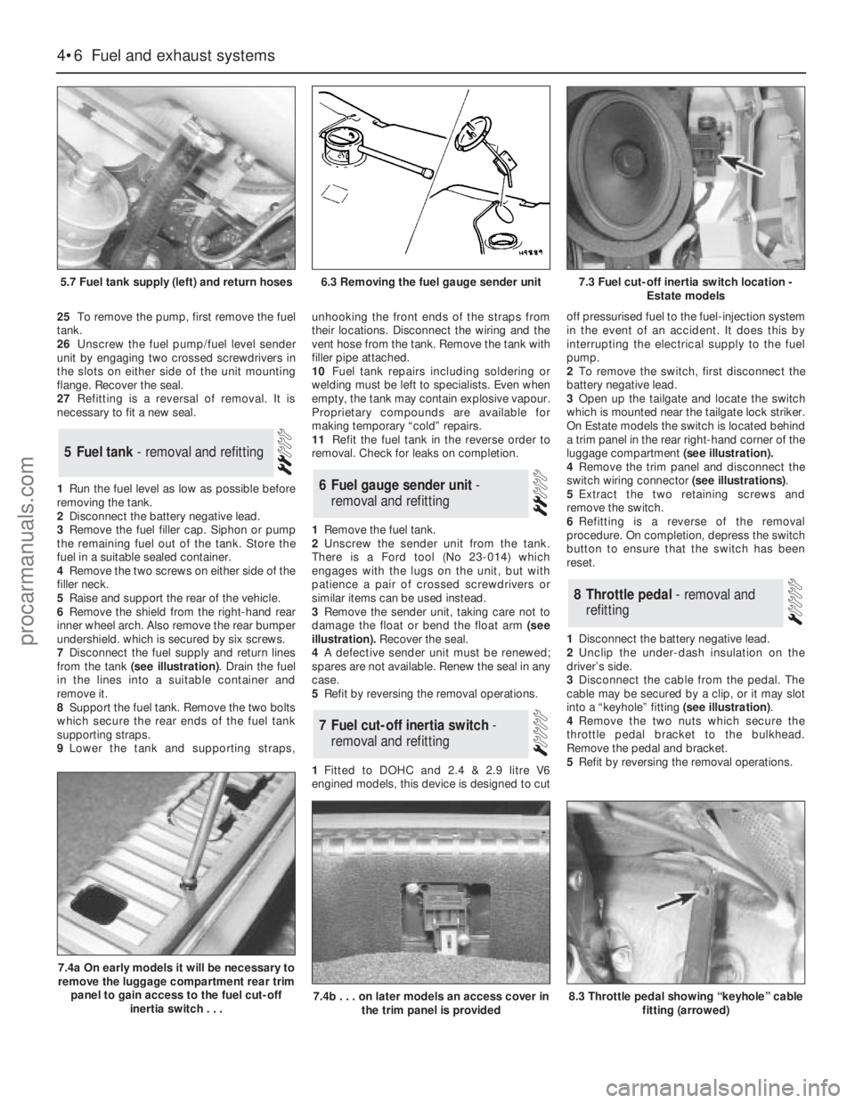
7Disconnect the fuel supply and return lines
from the tank (see illustration). Drain the fuel
in the lines into a suitable container and
remove it.
8Support the fuel tank. Remove the two bolts
which secure the rear ends of the fuel tank
supporting straps.
9Lower the tank and supporting straps,unhooking the front ends of the straps from
their locations. Disconnect the wiring and the
vent hose from the tank. Remove the tank with
filler pipe attached.
10Fuel tank repairs including soldering or
welding must be left to specialists. Even when
empty, the tank may contain explosive vapour.
Proprietary compounds are available for
making temporary “cold” repairs.
11Refit the fuel tank in the reverse order to
removal. Check for leaks on completion.
1Remove the fuel tank.
2Unscrew the sender unit from the tank.
There is a Ford tool (No 23-014) which
engages with the lugs on the unit, but with
patience a pair of crossed screwdrivers or
similar items can be used instead.
3Remove the sender unit, taking care not to
damage the float or bend the float arm(see
illustration).Recover the seal.
4A defective sender unit must be renewed;
spares are not available. Renew the seal in any
case.
5Refit by reversing the removal operations.
1Fitted to DOHC and 2.4 & 2.9 litre V6
engined models, this device is designed to cutoff pressurised fuel to the fuel-injection system
in the event of an accident. It does this by
interrupting the electrical supply to the fuel
pump.
2To remove the switch, first disconnect the
battery negative lead.
3Open up the tailgate and locate the switch
which is mounted near the tailgate lock striker.
On Estate models the switch is located behind
a trim panel in the rear right-hand corner of the
luggage compartment (see illustration).
4Remove the trim panel and disconnect the
switch wiring connector (see illustrations).
5Extract the two retaining screws and
remove the switch.
6Refitting is a reverse of the removal
procedure. On completion, depress the switch
button to ensure that the switch has been
reset.
1Disconnect the battery negative lead.
2Unclip the under-dash insulation on the
driver’s side.
3Disconnect the cable from the pedal. The
cable may be secured by a clip, or it may slot
into a “keyhole” fitting (see illustration).
4Remove the two nuts which secure the
throttle pedal bracket to the bulkhead.
Remove the pedal and bracket.
5Refit by reversing the removal operations.
8Throttle pedal - removal and
refitting
7Fuel cut-off inertia switch -
removal and refitting
6Fuel gauge sender unit -
removal and refitting
5Fuel tank - removal and refitting
4•6Fuel and exhaust systems
5.7 Fuel tank supply (left) and return hoses
7.4a On early models it will be necessary to
remove the luggage compartment rear trim
panel to gain access to the fuel cut-off
inertia switch . . .
7.4b . . . on later models an access cover in
the trim panel is provided8.3 Throttle pedal showing “keyhole” cable
fitting (arrowed)
6.3 Removing the fuel gauge sender unit7.3 Fuel cut-off inertia switch location -
Estate models
procarmanuals.com
Page 102 of 255
1Check the cost and availability of spare parts
before deciding to dismantle the carburettor. If
the unit has seen much service, fitting a new or
reconditioned carburettor may prove more
satisfactory than any attempt at overhaul.
2Obtain a carburettor repair kit, which will
contain the necessary gaskets, diaphragms
and other renewable items.
3With the carburettor removed from the
vehicle, clean it thoroughly externally and
place it on a clean worksurface.
4 Referringto the exploded view of the
carburettor(see illustration),remove each
component part whilst making a note of its
fitted position. Make alignment marks on
linkages etc.
5Reassemble in the reverse order to
dismantling, using new gaskets, O-rings etc.
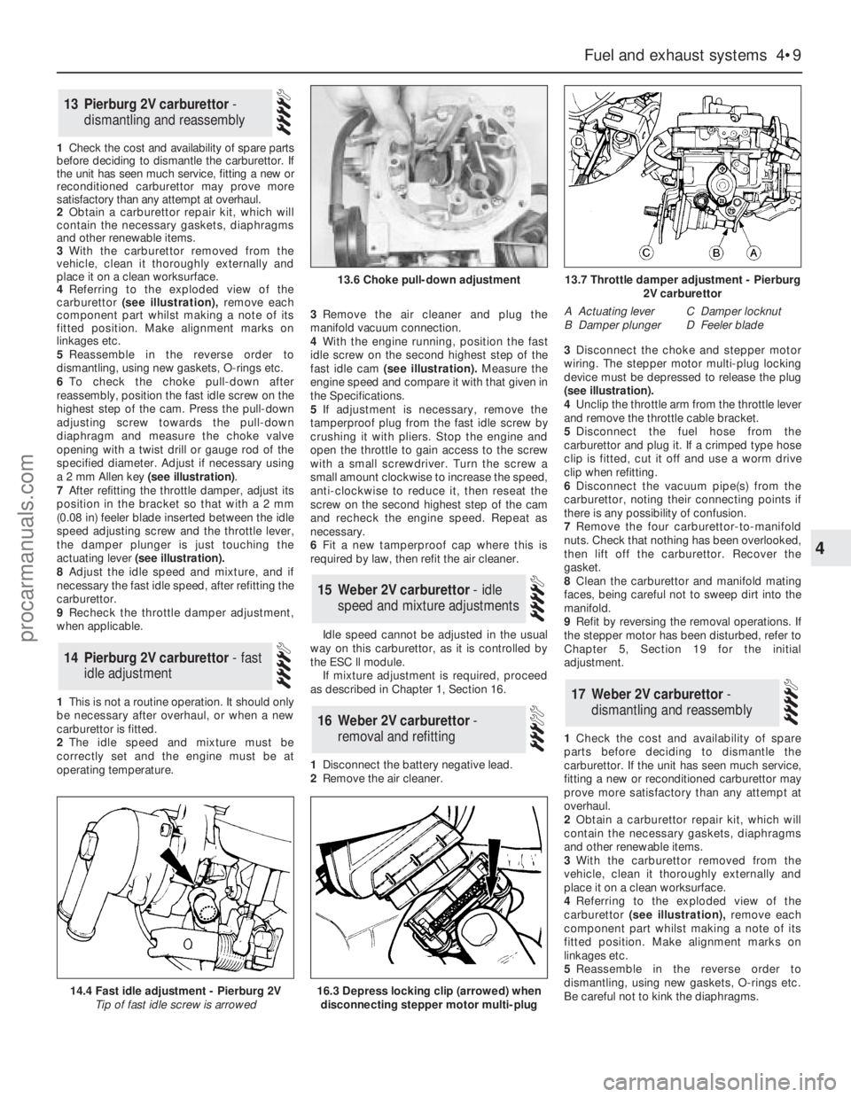
6To check the choke pull-down after
reassembly, position the fast idle screw on the
highest step of the cam. Press the pull-down
adjusting screw towards the pull-down
diaphragm and measure the choke valve
opening with a twist drill or gauge rod of the
specified diameter. Adjust if necessary using
a 2 mm Allen key (see illustration).
7After refitting the throttle damper, adjust its
position in the bracket so that with a 2 mm
(0.08 in) feeler blade inserted between the idle
speed adjusting screw and the throttle lever,
the damper plunger is just touching the
actuating lever(see illustration).
8Adjust the idle speed and mixture, and if
necessary the fast idle speed, after refitting the
carburettor.
9Recheck the throttle damper adjustment,
when applicable.
1This is not a routine operation. It should only
be necessary after overhaul, or when a new
carburettor is fitted.
2The idle speed and mixture must be
correctly set and the engine must be at
operating temperature.3Remove the air cleaner and plug the
manifold vacuum connection.
4With the engine running, position the fast
idle screw on the second highest step of the
fast idle cam(see illustration).Measure the
engine speed and compare it with that given in
the Specifications.
5If adjustment is necessary, remove the
tamperproof plug from the fast idle screw by
crushing it with pliers. Stop the engine and
open the throttle to gain access to the screw
with a small screwdriver. Turn the screw a
small amount clockwise to increase the speed,
anti-clockwise to reduce it, then reseat the
screw on the second highest step of the cam
and recheck the engine speed. Repeat as
necessary.
6Fit a new tamperproof cap where this is
required by law, then refit the air cleaner.
Idle speed cannot be adjusted in the usual
way on this carburettor, as it is controlled by
the ESC ll module.
If mixture adjustment is required, proceed
as described in Chapter 1, Section 16.
1Disconnect the battery negative lead.
2Remove the air cleaner.3Disconnect the choke and stepper motor
wiring. The stepper motor multi-plug locking
device must be depressed to release the plug
(seeillustration).
4Unclip the throttle arm from the throttle lever
and remove the throttle cable bracket.
5Disconnect the fuel hose from the
carburettor and plug it. If a crimped type hose
clip is fitted, cut it off and use a worm drive
clip when refitting.
6Disconnect the vacuum pipe(s) from the
carburettor, noting their connecting points if
there is any possibility of confusion.
7Remove the four carburettor-to-manifold
nuts. Check that nothing has been overlooked,
then lift off the carburettor. Recover the
gasket.
8Clean the carburettor and manifold mating
faces, being careful not to sweep dirt into the
manifold.
9Refit by reversing the removal operations. If
the stepper motor has been disturbed, refer to
Chapter 5, Section 19 for the initial
adjustment.
1Check the cost and availability of spare
parts before deciding to dismantle the
carburettor. If the unit has seen much service,
fitting a new or reconditioned carburettor may
prove more satisfactory than any attempt at
overhaul.
2Obtain a carburettor repair kit, which will
contain the necessary gaskets, diaphragms
and other renewable items.
3With the carburettor removed from the
vehicle, clean it thoroughly externally and
place it on a clean worksurface.
4 Referringto the exploded view of the
carburettor(see illustration),remove each
component part whilst making a note of its
fitted position. Make alignment marks on
linkages etc.
5Reassemble in the reverse order to
dismantling, using new gaskets, O-rings etc.
Be careful not to kink the diaphragms.
17Weber 2V carburettor -
dismantling and reassembly
16Weber 2V carburettor -
removal and refitting
15Weber 2V carburettor - idle
speed and mixture adjustments
14Pierburg 2V carburettor - fast
idle adjustment
13Pierburg 2V carburettor -
dismantling and reassembly
Fuel and exhaust systems 4•9
4
14.4 Fast idle adjustment - Pierburg 2V
Tip of fast idle screw is arrowed
13.6 Choke pull-down adjustment13.7 Throttle damper adjustment - Pierburg
2V carburettor
A Actuating lever
B Damper plungerC Damper locknut
D Feeler blade
16.3 Depress locking clip (arrowed) when
disconnecting stepper motor multi-plug
procarmanuals.com