1985 FORD GRANADA ESP
[x] Cancel search: ESPPage 9 of 255
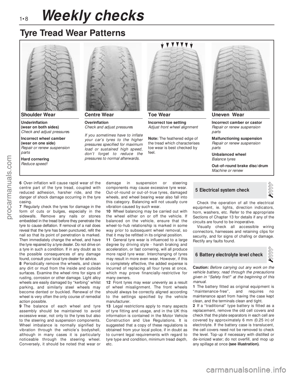
6Over-inflation will cause rapid wear of the
centre part of the tyre tread, coupled with
reduced adhesion, harsher ride, and the
danger of shock damage occurring in the tyre
casing.
7Regularly check the tyres for damage in the
form of cuts or bulges, especially in the
sidewalls. Remove any nails or stones
embedded in the tread before they penetrate the
tyre to cause deflation. If removal of a nail does
reveal that the tyre has been punctured, refit the
nail so that its point of penetration is marked.
Then immediately change the wheel, and have
the tyre repaired by a tyre dealer. Do not drive on
a tyre in such a condition. If in any doubt as to
the possible consequences of any damage
found, consult your local tyre dealer for advice.
8Periodically remove the wheels, and clean
any dirt or mud from the inside and outside
surfaces. Examine the wheel rims for signs of
rusting, corrosion or other damage. Light alloy
wheels are easily damaged by “kerbing” whilst
parking, and similarly steel wheels may
become dented or buckled. Renewal of the
wheel is very often the only course of remedial
action possible.
9The balance of each wheel and tyre
assembly should be maintained to avoid
excessive wear, not only to the tyres but also
to the steering and suspension components.
Wheel imbalance is normally signified by
vibration through the vehicle’s bodyshell,
although in many cases it is particularly
noticeable through the steering wheel.
Conversely, it should be noted that wear ordamage in suspension or steering
components may cause excessive tyre wear.
Out-of-round or out-of-true tyres, damaged
wheels, and wheel bearing wear also fall into
this category. Balancing will not usually cure
vibration caused by such wear.
10Wheel balancing may be carried out with
the wheel either on or off the vehicle. If
balanced on the vehicle, ensure that the
wheel-to-hub relationship is marked in some
way prior to subsequent wheel removal, so
that it may be refitted in its original position.
11General tyre wear is influenced to a large
degree by driving style - harsh braking and
acceleration, or fast cornering, will all produce
more rapid tyre wear. Interchanging of tyres
may result in more even wear. However, if this
is completely effective, the added expense is
incurred of replacing all four tyres at once,
which may prove financially-restrictive for
many owners.
12Front tyres may wear unevenly as a result
of wheel misalignment. The front wheels
should always be correctly aligned according
to the settings specified by the vehicle
manufacturer.
13Legal restrictions apply to many aspects
of tyre fitting and usage, and in the UK this
information is contained in the Motor Vehicle
Construction and Use Regulations. It is
suggested that a copy of these regulations is
obtained from your local police, if in doubt as
to current legal requirements with regard to
tyre type and condition, minimum tread depth,
etc.Check the operation of all the electrical
equipment, ie. lights, direction indicators,
horn, washers, etc. Refer to the appropriate
Sections of Chapter 13 for details if any of the
circuits are found to be inoperative.
Visually check all accessible wiring
connectors, harnesses and retaining clips for
security, and for signs of chafing or damage.
Rectify any faults found.
Caution: Before carrying out any work on the
vehicle battery, read through the precautions
given in “Safety first!” at the beginning of this
manual.
1The battery fitted as original equipment is
“maintenance-free”, and requires no
maintenance apart from having the case kept
clean, and the terminals clean and tight.
2If a “traditional” type battery is fitted as a
replacement, remove the old cell covers and
check that the plate separators in each cell are
covered by approximately 6 mm (0.25 in) of
electrolyte. If the battery case is translucent,
the cell covers need not be removed to check
the level. Top-up if necessary with distilled or
de-ionized water; do not overfill, and mop up
any spillage at once(see illustration).
6Battery electrolyte level check
5Electrical system check
1•8Weekly checks
Tyre Tread Wear Patterns
Shoulder Wear
Underinflation
(wear on both sides)
Check and adjust pressures
Incorrect wheel camber
(wear on one side)
Repair or renew suspension
parts
Hard cornering
Reduce speed!
Centre Wear
Overinflation
Check and adjust pressures
If you sometimes have to inflate
your car’s tyres to the higher
pressures specified for maximum
load or sustained high speed,
don’t forget to reduce the
pressures to normal afterwards.
Toe Wear
Incorrect toe setting
Adjust front wheel alignment
Note: The feathered edge of
the tread which characterises
toe wear is best checked by
feel.
Uneven Wear
Incorrect camber or castor
Repair or renew suspension
parts
Malfunctioning suspension
Repair or renew suspension
parts
Unbalanced wheel
Balance tyres
Out-of-round brake disc/drum
Machine or renew
procarmanuals.com
Page 11 of 255
1Firmly apply the handbrake, then jack up the
front and rear of the car and support it
securely on axle stands (see “Jacking”).
2For a quick check, the front brake disc pads
can be inspected without removing the front
wheels, using a mirror and a torch through the
aperture in the rear face of the caliper. If any
one pad is worn down to the minimum
specified, all four pads (on both front wheels)
must be renewed.
3It is necessary to remove the rear wheels in
order to inspect the rear pads. The pads can
be viewed through the top of the caliper after
removing the spring clip. If any one pad is
worn down to the minimum specified, all four
pads (on both rear wheels) must be renewed.
4For a comprehensive check, the brake pads
should be removed and cleaned. The
operation of the caliper can then also be
checked, and the condition of the brake discs
can be fully examined on both sides. Refer to
Chapter 10 for further information.
5At the same interval, check the function of
the brake fluid level warning light. Chock the
wheels, release the handbrake and switch on
the ignition. Unscrew and raise the brake fluid
reservoir cap whilst an assistant observes the
warning light: it should come on as the level
sensor is withdrawn from the fluid. Refit the
cap.
6On completion, refit the wheels and lower
the car to the ground.
1Visually inspect the engine joint faces,
gaskets and seals for any signs of water or oil
leaks. Pay particular attention to the areas
around the rocker cover, cylinder head, oil
filter and sump joint faces. Bear in mind that
over a period of time some very slight seepage
from these areas is to be expected but what
you are really looking for is any indication of a
serious leak. Should a leak be found, renew
the offending gasket or oil seal by referring to
the appropriate Chapter(s) in this manual.
2Similarly, check the transmission for oil
leaks, and investigate and rectify and
problems found.
3Check the security and condition of all the
engine related pipes and hoses. Ensure that all
cable-ties or securing clips are in place and in
good condition. Clips which are broken or
missing can lead to chafing of the hoses,
pipes or wiring which could cause more
serious problems in the future.
4Carefully check the condition of all coolant,
fuel and brake hoses. Renew any hose which
is cracked, swollen or deteriorated. Cracks will
show up better if the hose is squeezed. Pay
close attention to the hose clips that secure
the hoses to the system components. Hoseclips can pinch and puncture hoses, resulting
in leaks. If wire type hose clips are used, it
may be a good idea to replace them with
screw-type clips.
5With the vehicle raised, inspect the fuel tank
and filler neck for punctures, cracks and other
damage. The connection between the filler neck
and tank is especially critical. Sometimes a
rubber filler neck or connecting hose will leak due
to loose retaining clamps or deteriorated rubber.
6Similarly, inspect all brake hoses and metal
pipes. If any damage or deterioration is
discovered, do not drive the vehicle until the
necessary repair work has been carried out.
Renew any damaged sections of hose or pipe.
7Carefully check all rubber hoses and metal
fuel lines leading away from the petrol tank.
Check for loose connections, deteriorated
hoses, crimped lines and other damage. Pay
particular attention to the vent pipes and
hoses which often loop up around the filler
neck and can become blocked or crimped.
Follow the lines to the front of the vehicle
carefully inspecting them all the way. Renew
damaged sections as necessary.
8From within the engine compartment, check
the security of all fuel hose attachments and
pipe unions, and inspect the fuel hoses and
vacuum hoses for kinks, chafing and
deterioration.
9Where applicable, check the condition of
the oil cooler hoses and pipes.
10Check the condition of all exposed wiring
harnesses.
11Also check the engine and transmission
components for signs of fluid leaks.
Periodically check the belts for fraying or
other damage. If evident, renew the belt.
If the belts become dirty, wipe them with a
damp cloth using a little detergent only.
Check the tightness of the anchor bolts and
if they are ever disconnected, make quite sure
that the original sequence of fitting of washers,
bushes and anchor plates is retained.With the vehicle raised on a hoist or
supported on axle stands (see “Jacking”),
check the exhaust system for signs of leaks,
corrosion or damage and check the rubber
mountings for condition and security. Where
damage or corrosion are evident, renew the
system complete or in sections, as applicable,
using the information given in Chapter 4.
With the wheels on the ground, slacken
each wheel nut by a quarter turn, then
retighten it immediately to the specified
torque.
Remove and clean the oil filler cap of any
sludge build-up using paraffin.
Inspect the vent hose for blockage or
damage. A blocked hose can cause a build-up
of crankcase pressure, which in turn can
cause oil leaks.
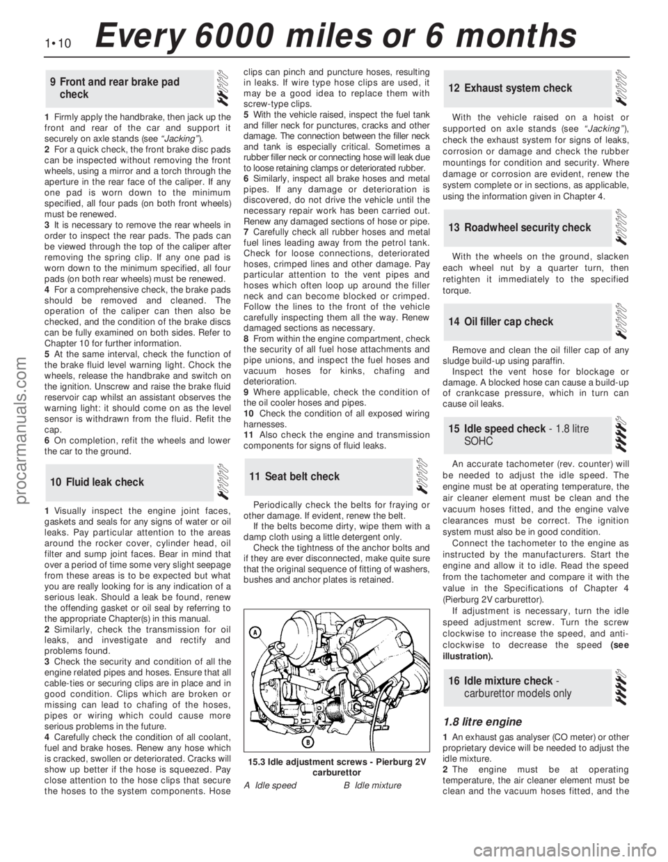
An accurate tachometer (rev. counter) will
be needed to adjust the idle speed. The
engine must be at operating temperature, the
air cleaner element must be clean and the
vacuum hoses fitted, and the engine valve
clearances must be correct. The ignition
system must also be in good condition.
Connect the tachometer to the engine as
instructed by the manufacturers. Start the
engine and allow it to idle. Read the speed
from the tachometer and compare it with the
value in the Specifications of Chapter 4
(Pierburg 2V carburettor).
If adjustment is necessary, turn the idle
speed adjustment screw. Turn the screw
clockwise to increase the speed, and anti-
clockwise to decrease the speed (see
illustration).
1.8 litre engine
1An exhaust gas analyser (CO meter) or other
proprietary device will be needed to adjust the
idle mixture.
2The engine must be at operating
temperature, the air cleaner element must be
clean and the vacuum hoses fitted, and the
16Idle mixture check -
carburettor models only
15Idle speed check - 1.8 litre
SOHC
14Oil filler cap check
13Roadwheel security check
12Exhaust system check
11Seat belt check10Fluid leak check
9Front and rear brake pad
check
1•10Every 6000 miles or 6 months
15.3 Idle adjustment screws - Pierburg 2V
carburettor
A Idle speedB Idle mixture
procarmanuals.com
Page 37 of 255
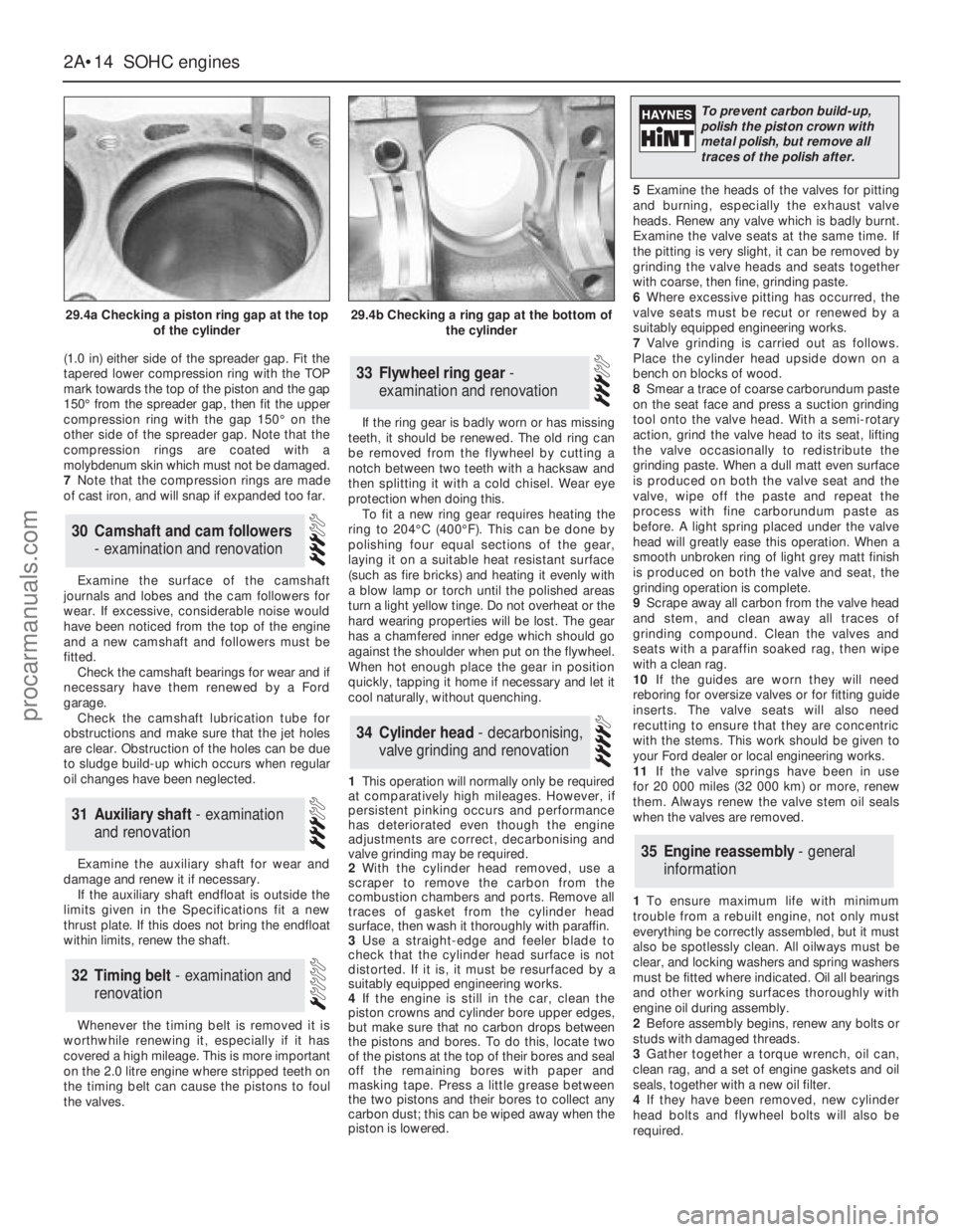
(1.0 in) either side of the spreader gap. Fit the
tapered lower compression ring with the TOP
mark towards the top of the piston and the gap
150°from the spreader gap, then fit the upper
compression ring with the gap 150°on the
other side of the spreader gap. Note that the
compression rings are coated with a
molybdenum skin which must not be damaged.
7Note that the compression rings are made
of cast iron, and will snap if expanded too far.
Examine the surface of the camshaft
journals and lobes and the cam followers for
wear. If excessive, considerable noise would
have been noticed from the top of the engine
and a new camshaft and followers must be
fitted.
Check the camshaft bearings for wear and if
necessary have them renewed by a Ford
garage.
Check the camshaft lubrication tube for
obstructions and make sure that the jet holes
are clear. Obstruction of the holes can be due
to sludge build-up which occurs when regular
oil changes have been neglected.
Examine the auxiliary shaft for wear and
damage and renew it if necessary.
If the auxiliary shaft endfloat is outside the
limits given in the Specifications fit a new
thrust plate. If this does not bring the endfloat
within limits, renew the shaft.
Whenever the timing belt is removed it is
worthwhile renewing it, especially if it has
covered a high mileage. This is more important
on the 2.0 litre engine where stripped teeth on
the timing belt can cause the pistons to foul
the valves.If the ring gear is badly worn or has missing
teeth, it should be renewed. The old ring can
be removed from the flywheel by cutting a
notch between two teeth with a hacksaw and
then splitting it with a cold chisel. Wear eye
protection when doing this.
To fit a new ring gear requires heating the
ring to 204°C (400°F). This can be done by
polishing four equal sections of the gear,
laying it on a suitable heat resistant surface
(such as fire bricks) and heating it evenly with
a blow lamp or torch until the polished areas
turn a light yellow tinge. Do not overheat or the
hard wearing properties will be lost. The gear
has a chamfered inner edge which should go
against the shoulder when put on the flywheel.
When hot enough place the gear in position
quickly, tapping it home if necessary and let it
cool naturally, without quenching.
1This operation will normally only be required
at comparatively high mileages. However, if
persistent pinking occurs and performance
has deteriorated even though the engine
adjustments are correct, decarbonising and
valve grinding may be required.
2With the cylinder head removed, use a
scraper to remove the carbon from the
combustion chambers and ports. Remove all
traces of gasket from the cylinder head
surface, then wash it thoroughly with paraffin.
3Use a straight-edge and feeler blade to
check that the cylinder head surface is not
distorted. If it is, it must be resurfaced by a
suitably equipped engineering works.
4If the engine is still in the car, clean the
piston crowns and cylinder bore upper edges,
but make sure that no carbon drops between
the pistons and bores. To do this, locate two
of the pistons at the top of their bores and seal
off the remaining bores with paper and
masking tape. Press a little grease between
the two pistons and their bores to collect any
carbon dust; this can be wiped away when the
piston is lowered.5Examine the heads of the valves for pitting
and burning, especially the exhaust valve
heads. Renew any valve which is badly burnt.
Examine the valve seats at the same time. If
the pitting is very slight, it can be removed by
grinding the valve heads and seats together
with coarse, then fine, grinding paste.
6Where excessive pitting has occurred, the
valve seats must be recut or renewed by a
suitably equipped engineering works.
7Valve grinding is carried out as follows.
Place the cylinder head upside down on a
bench on blocks of wood.
8Smear a trace of coarse carborundum paste
on the seat face and press a suction grinding
tool onto the valve head. With a semi-rotary
action, grind the valve head to its seat, lifting
the valve occasionally to redistribute the
grinding paste. When a dull matt even surface
is produced on both the valve seat and the
valve, wipe off the paste and repeat the
process with fine carborundum paste as
before. A light spring placed under the valve
head will greatly ease this operation. When a
smooth unbroken ring of light grey matt finish
is produced on both the valve and seat, the
grinding operation is complete.
9Scrape away all carbon from the valve head
and stem, and clean away all traces of
grinding compound. Clean the valves and
seats with a paraffin soaked rag, then wipe
with a clean rag.
10If the guides are worn they will need
reboring for oversize valves or for fitting guide
inserts. The valve seats will also need
recutting to ensure that they are concentric
with the stems. This work should be given to
your Ford dealer or local engineering works.
11If the valve springs have been in use
for 20 000 miles (32 000 km) or more, renew
them. Always renew the valve stem oil seals
when the valves are removed.
1To ensure maximum life with minimum
trouble from a rebuilt engine, not only must
everything be correctly assembled, but it must
also be spotlessly clean. All oilways must be
clear, and locking washers and spring washers
must be fitted where indicated. Oil all bearings
and other working surfaces thoroughly with
engine oil during assembly.
2Before assembly begins, renew any bolts or
studs with damaged threads.
3Gather together a torque wrench, oil can,
clean rag, and a set of engine gaskets and oil
seals, together with a new oil filter.
4If they have been removed, new cylinder
head bolts and flywheel bolts will also be
required.
35Engine reassembly - general
information
34Cylinder head - decarbonising,
valve grinding and renovation
33Flywheel ring gear -
examination and renovation
32Timing belt - examination and
renovation
31Auxiliary shaft - examination
and renovation
30Camshaft and cam followers
- examination and renovation
2A•14SOHCengines
29.4a Checking a piston ring gap at the top
of the cylinder29.4b Checking a ring gap at the bottom of
the cylinder
To prevent carbon build-up,
polish the piston crown with
metal polish, but remove all
traces of the polish after.
procarmanuals.com
Page 43 of 255
See Chapter 1, Section 23.
1Make a final check to ensure that everything
has been reconnected to the engine and that no
rags or tools have been left in the engine bay.
2Check that oil and coolant levels are
correct.
3Start the engine. This may take a little longer
than usual as fuel is pumped up to the engine.
4Check that the oil pressure light goes out
when the engine starts.
5Run the engine at a fast tickover and check
for leaks of oil, fuel and coolant. Also check
power steering and transmission fluid cooler
unions, when applicable. Some smoke and
odd smells may be experienced as assembly
lubricant burns off the exhaust manifold and
other components.6Bring the engine to operating temperature.
Check the ignition timing then adjust the idle
speed (if applicable) and mixture.
7Stop the engine and allow it to cool, then re-
check the oil and coolant levels.
8If new bearings, pistons etc have been
fitted, the engine should be run in at reduced
speeds and loads for the first 500 miles (800
km) or so. It is beneficial to change the engine
oil and filter after this mileage.
1When engine performance is down, or if
misfiring occurs which cannot be attributed to
the ignition or fuel system, a compression test
can provide diagnostic clues. If the test is
performed regularly it can give warning of
trouble before any other symptoms become
apparent.
2The engine must be at operating
temperature, the battery must be fully charged
and the spark plugs must be removed. The
services of an assistant will also be required.
3Disable the ignition system by dismantlingthe coil LT feed. Fit the compression tester to
No 1 spark plug hole. (The type of tester which
screws into the spark plug hole is to be
preferred.)
4Have the assistant hold the throttle wide
open and crank the engine on the starter.
Record the highest reading obtained on the
compression tester.
5Repeat the test on the remaining cylinders,
recording the pressure developed in each.
6Desired pressures are given in the
Specifications. If the pressure in any cylinder
is low, introduce a teaspoonful of clean engine
oil into the spark plug hole and repeat the test.
7If the addition of oil temporarily improves
the compression pressure, this indicates that
bore or piston wear was responsible for the
pressure loss. No improvement suggests that
leaking or burnt valves, or a blown head
gasket, may be to blame.
8A low reading from two adjacent cylinders is
almost certainly due to the head gasket
between them having blown.
9On completion of the test, refit the spark
plugs and reconnect the coil LT feed.
52Compression test -
description and interpretation
51Initial start-up after overhaul
or major repair
50Valve clearances - checking
and adjustment
2A•20SOHCengines
procarmanuals.com
Page 53 of 255
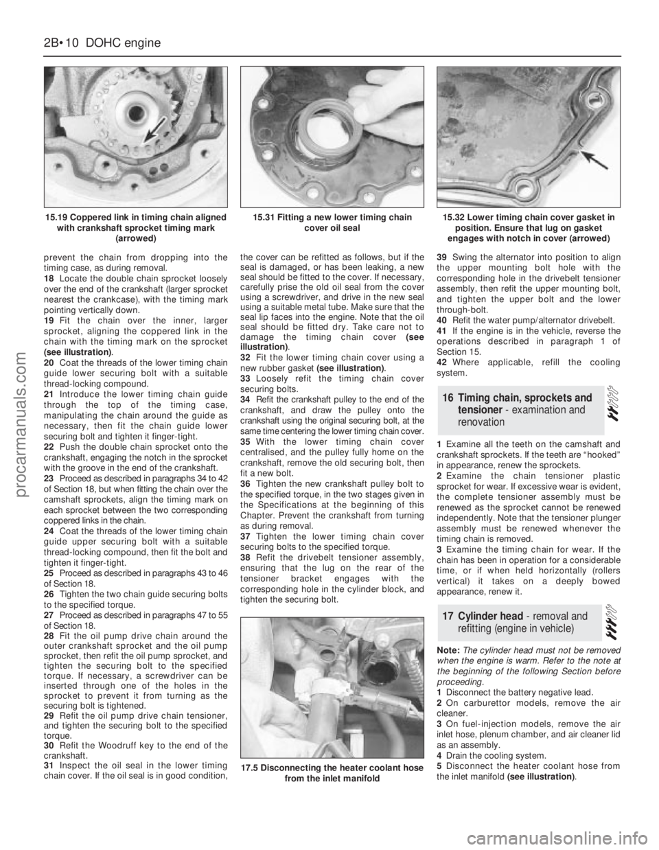
prevent the chain from dropping into the
timing case, as during removal.
18Locate the double chain sprocket loosely
over the end of the crankshaft (larger sprocket
nearest the crankcase), with the timing mark
pointing vertically down.
19Fit the chain over the inner, larger
sprocket, aligning the coppered link in the
chain with the timing mark on the sprocket
(see illustration).
20Coat the threads of the lower timing chain
guide lower securing bolt with a suitable
thread-locking compound.
21Introduce the lower timing chain guide
through the top of the timing case,
manipulating the chain around the guide as
necessary, then fit the chain guide lower
securing bolt and tighten it finger-tight.
22Push the double chain sprocket onto the
crankshaft, engaging the notch in the sprocket
with the groove in the end of the crankshaft.
23Proceed as described in paragraphs 34 to 42
of Section 18, but when fitting the chain over the
camshaft sprockets, align the timing mark on
each sprocket between the two corresponding
coppered links in the chain.
24Coat the threads of the lower timing chain
guide upper securing bolt with a suitable
thread-locking compound, then fit the bolt and
tighten it finger-tight.
25Proceed as described in paragraphs 43 to 46
of Section 18.
26Tighten the two chain guide securing bolts
to the specified torque.
27Proceed as described in paragraphs 47 to 55
of Section 18.
28Fit the oil pump drive chain around the
outer crankshaft sprocket and the oil pump
sprocket, then refit the oil pump sprocket, and
tighten the securing bolt to the specified
torque. If necessary, a screwdriver can be
inserted through one of the holes in the
sprocket to prevent it from turning as the
securing bolt is tightened.
29Refit the oil pump drive chain tensioner,
and tighten the securing bolt to the specified
torque.
30Refit the Woodruff key to the end of the
crankshaft.
31Inspect the oil seal in the lower timing
chain cover. If the oil seal is in good condition,the cover can be refitted as follows, but if the
seal is damaged, or has been leaking, a new
seal should be fitted to the cover. If necessary,
carefully prise the old oil seal from the cover
using a screwdriver, and drive in the new seal
using a suitable metal tube. Make sure that the
seal lip faces into the engine. Note that the oil
seal should be fitted dry. Take care not to
damage the timing chain cover (see
illustration).
32Fit the lower timing chain cover using a
new rubber gasket (see illustration).
33Loosely refit the timing chain cover
securing bolts.
34Refit the crankshaft pulley to the end of the
crankshaft, and draw the pulley onto the
crankshaft using the original securing bolt, at the
same time centering the lower timing chain cover.
35With the lower timing chain cover
centralised, and the pulley fully home on the
crankshaft, remove the old securing bolt, then
fit a new bolt.
36Tighten the new crankshaft pulley bolt to
the specified torque, in the two stages given in
the Specifications at the beginning of this
Chapter. Prevent the crankshaft from turning
as during removal.
37Tighten the lower timing chain cover
securing bolts to the specified torque.
38Refit the drivebelt tensioner assembly,
ensuring that the lug on the rear of the
tensioner bracket engages with the
corresponding hole in the cylinder block, and
tighten the securing bolt.39Swing the alternator into position to align
the upper mounting bolt hole with the
corresponding hole in the drivebelt tensioner
assembly, then refit the upper mounting bolt,
and tighten the upper bolt and the lower
through-bolt.
40Refit the water pump/alternator drivebelt.
41If the engine is in the vehicle, reverse the
operations described in paragraph 1 of
Section 15.
42Where applicable, refill the cooling
system.
1Examine all the teeth on the camshaft and
crankshaft sprockets. If the teeth are “hooked”
in appearance, renew the sprockets.
2Examine the chain tensioner plastic
sprocket for wear. If excessive wear is evident,
the complete tensioner assembly must be
renewed as the sprocket cannot be renewed
independently.Note that the tensioner plunger
assembly must be renewed whenever the
timing chain is removed.
3Examine the timing chain for wear. If the
chain has been in operation for a considerable
time, or if when held horizontally (rollers
vertical) it takes on a deeply bowed
appearance, renew it.
Note: The cylinder head must not be removed
when the engine is warm. Refer to the note at
the beginning of the following Section before
proceeding.
1Disconnect the battery negative lead.
2On carburettor models, remove the air
cleaner.
3On fuel-injection models, remove the air
inlet hose, plenum chamber, and air cleaner lid
as an assembly.
4Drain the cooling system.
5Disconnect the heater coolant hose from
the inlet manifold (see illustration).
17Cylinder head - removal and
refitting (engine in vehicle)
16Timing chain, sprockets and
tensioner - examination and
renovation
2B•10DOHCengine
15.19 Coppered link in timing chain aligned
with crankshaft sprocket timing mark
(arrowed)
17.5 Disconnecting the heater coolant hose
from the inlet manifold
15.31 Fitting a new lower timing chain
cover oil seal15.32 Lower timing chain cover gasket in
position. Ensure that lug on gasket
engages with notch in cover (arrowed)
procarmanuals.com
Page 54 of 255
6Disconnect the breather hose from the
camshaft cover, and unbolt the hose bracket
from the left-hand side of the cylinder head
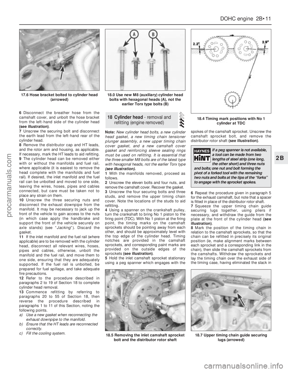
(see illustration).
7Unscrew the securing bolt and disconnect
the earth lead from the left-hand rear of the
cylinder head.
8Remove the distributor cap and HT leads,
and the rotor arm and housing, as applicable.
If necessary, mark the HT leads to aid refitting.
9The cylinder head can be removed either
with or without the manifolds and fuel rail,
where applicable (it is easiest to remove the
head complete with the manifolds and fuel
rail). If desired, the inlet manifold and the fuel
rail can be unbolted and moved to one side,
leaving the wires, hoses, pipes and cables
connected, but care must be taken not to
place any strain on them.
10Unscrew the three securing nuts and
disconnect the exhaust downpipe from the
manifold. It may be necessary to jack up the
front of the vehicle to gain access to the nuts
(in which case apply the handbrake and
support the front of the vehicle securely on
axle stands) (see “Jacking”). Discard the
gasket.
11If the inlet manifold and the fuel rail (where
applicable) are to be removed with the cylinder
head, disconnect all relevant wires, hoses,
pipes and cables, otherwise, unbolt the
manifold and the fuel rail, and move them to
one side, ensuring that they are adequately
supported. If the fuel rail is unbolted, be
prepared for fuel spillage, and take adequate
fire precautions.
12Refer to the procedure described in
paragraphs 2 to 19 of Section 18 to complete
cylinder head removal.
13Commence refitting by referring to
paragraphs 20 to 55 of Section 18, then
reverse the procedure described in
paragraphs 1 to 11 of this Section, noting the
following points.
a)Use a new gasket when reconnecting the
exhaust downpipe to the manifold.
b)Ensure that the HT leads are reconnected
correctly.
c)Fill the cooling system.Note: New cylinder head bolts, a new cylinder
head gasket, a new timing chain tensioner
plunger assembly, a new upper timing chain
cover gasket, and a new camshaft cover
gasket and reinforcing sleeve sealing rings
must be used on refitting. It is essential that
the three smaller M8 bolts are of the latest type
with hexagonal heads, not the earlier Torx type
(see illustration).
1With the manifolds removed, proceed as
follows.
2Unscrew the eleven bolts and four nuts, and
remove the camshaft cover. Recover the gasket.
3Unscrew the four securing bolts and three
studs, and remove the upper timing chain
cover. Note the locations of the studs to aid
refitting.
4Using a spanner on the crankshaft pulley,
turn the crankshaft to bring No 1 piston to the
firing point (TDC). With No 1 piston at the firing
point, the timing marks on the camshaft
sprockets should be pointing away from each
other, and should be approximately level with
the top edge of the cylinder head. Timing
notches are provided in the camshaft
sprockets, and corresponding paint marks are
provided on the outside edges of the
sprockets (see illustration).
5Hold the inlet camshaft sprocket stationary
using a peg spanner which engages with thespokes of the camshaft sprocket. Unscrew the
camshaft sprocket bolt, and remove the
distributor rotor shaft (see illustration).
6Repeat the procedure given in paragraph 5
for the exhaust camshaft, but note that a spacer
is fitted in place of the distributor rotor shaft.
7Squeeze the upper timing chain guide
securing lugs together, using pliers if
necessary, and withdraw the guide from the
plate at the front of the cylinder head (see
illustration).
8Mark the position of the timing chain in
relation to the camshaft sprockets, so that the
chain can be refitted in precisely its original
position (ie, make alignment marks between
each sprocket and a corresponding link in the
chain), then slide the camshaft sprockets from
the camshafts. Withdraw the sprockets and
lay the timing chain over the exhaust side of
the timing case, having eliminated the slack in18Cylinder head - removal and
refitting (engine removed)
DOHCengine 2B•11
2B
17.6 Hose bracket bolted to cylinder head
(arrowed)18.0 Use new M8 (auxiliary) cylinder head
bolts with hexagonal heads (A), not the
earlier Torx type bolts (B)
18.4 Timing mark positions with No 1
cylinder at TDC
18.5 Removing the inlet camshaft sprocket
bolt and the distributor rotor shaft18.7 Upper timing chain guide securing
lugs (arrowed)
If a peg spanner is not available,
a tool can be made from two
lengths of steel strip (one long,
the other short) and three nuts
and bolts; one nut and bolt forming the
pivot of a forked tool with the remaining
two nuts and bolts at the tips of the “forks”
to engage with the sprocket spokes.
procarmanuals.com
Page 61 of 255
9Extract the bearing shells, and recover the
thrustwashers, keeping them identified for
location.
10The crankshaft and bearings can be
examined and if necessary renovated.
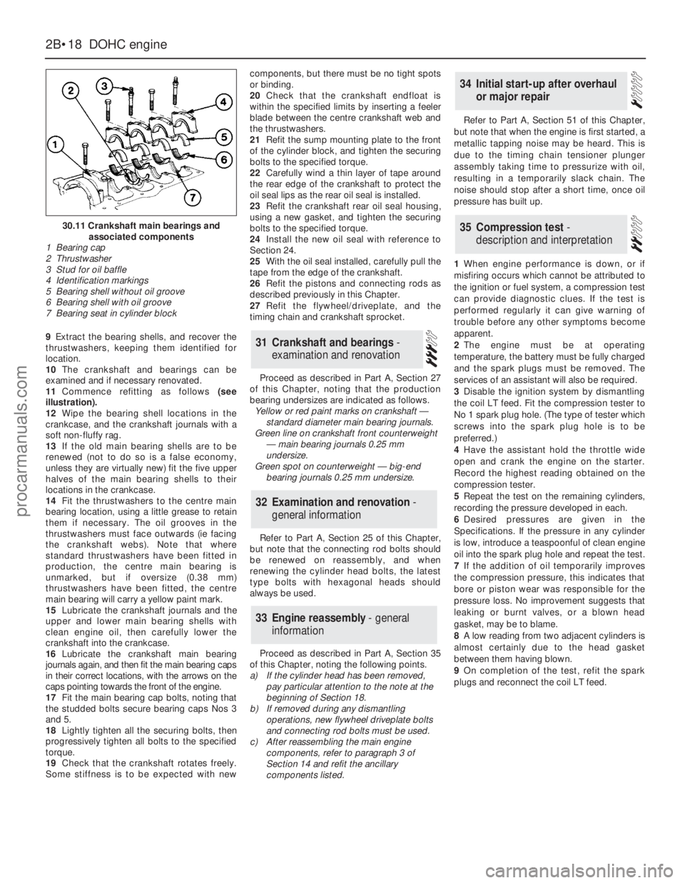
11Commence refitting as follows(see
illustration).
12Wipe the bearing shell locations in the
crankcase, and the crankshaft journals with a
soft non-fluffy rag.
13If the old main bearing shells are to be
renewed (not to do so is a false economy,
unless they are virtually new) fit the five upper
halves of the main bearing shells to their
locations in the crankcase.
14Fit the thrustwashers to the centre main
bearing location, using a little grease to retain
them if necessary. The oil grooves in the
thrustwashers must face outwards (ie facing
the crankshaft webs). Note that where
standard thrustwashers have been fitted in
production, the centre main bearing is
unmarked, but if oversize (0.38 mm)
thrustwashers have been fitted, the centre
main bearing will carry a yellow paint mark.
15Lubricate the crankshaft journals and the
upper and lower main bearing shells with
clean engine oil, then carefully lower the
crankshaft into the crankcase.
16Lubricate the crankshaft main bearing
journals again, and then fit the main bearing caps
in their correct locations, with the arrows on the
caps pointing towards the front of the engine.
17Fit the main bearing cap bolts, noting that
the studded bolts secure bearing caps Nos 3
and 5.
18Lightly tighten all the securing bolts, then
progressively tighten all bolts to the specified
torque.
19Check that the crankshaft rotates freely.
Some stiffness is to be expected with newcomponents, but there must be no tight spots
or binding.
20Check that the crankshaft endfloat is
within the specified limits by inserting a feeler
blade between the centre crankshaft web and
the thrustwashers.
21Refit the sump mounting plate to the front
of the cylinder block, and tighten the securing
bolts to the specified torque.
22Carefully wind a thin layer of tape around
the rear edge of the crankshaft to protect the
oil seal lips as the rear oil seal is installed.
23Refit the crankshaft rear oil seal housing,
using a new gasket, and tighten the securing
bolts to the specified torque.
24Install the new oil seal with reference to
Section 24.
25With the oil seal installed, carefully pull the
tape from the edge of the crankshaft.
26Refit the pistons and connecting rods as
described previously in this Chapter.
27Refit the flywheel/driveplate, and the
timing chain and crankshaft sprocket.
Proceed as described in Part A, Section 27
of this Chapter, noting that the production
bearing undersizes are indicated as follows.
Yellow or red paint marks on crankshaft —
standard diameter main bearing journals.
Green line on crankshaft front counterweight
— main bearing journals 0.25 mm
undersize.
Green spot on counterweight — big-end
bearing journals 0.25 mm undersize.
Refer to Part A, Section 25 of this Chapter,
but note that the connecting rod bolts should
be renewed on reassembly, and when
renewing the cylinder head bolts, the latest
type bolts with hexagonal heads should
always be used.
Proceed as described in Part A, Section 35
of this Chapter, noting the following points.
a)If the cylinder head has been removed,
pay particular attention to the note at the
beginning of Section 18.
b)If removed during any dismantling
operations, new flywheel driveplate bolts
and connecting rod bolts must be used.
c)After reassembling the main engine
components, refer to paragraph 3 of
Section 14 and refit the ancillary
components listed.Refer to Part A, Section 51 of this Chapter,
but note that when the engine is first started, a
metallic tapping noise may be heard. This is
due to the timing chain tensioner plunger
assembly taking time to pressurize with oil,
resulting in a temporarily slack chain. The
noise should stop after a short time, once oil
pressure has built up.
1When engine performance is down, or if
misfiring occurs which cannot be attributed to
the ignition or fuel system, a compression test
can provide diagnostic clues. If the test is
performed regularly it can give warning of
trouble before any other symptoms become
apparent.
2The engine must be at operating
temperature, the battery must be fully charged
and the spark plugs must be removed. The
services of an assistant will also be required.
3Disable the ignition system by dismantling
the coil LT feed. Fit the compression tester to
No 1 spark plug hole. (The type of tester which
screws into the spark plug hole is to be
preferred.)
4Have the assistant hold the throttle wide
open and crank the engine on the starter.
Record the highest reading obtained on the
compression tester.
5Repeat the test on the remaining cylinders,
recording the pressure developed in each.
6Desired pressures are given in the
Specifications. If the pressure in any cylinder
is low, introduce a teaspoonful of clean engine
oil into the spark plug hole and repeat the test.
7If the addition of oil temporarily improves
the compression pressure, this indicates that
bore or piston wear was responsible for the
pressure loss. No improvement suggests that
leaking or burnt valves, or a blown head
gasket, may be to blame.
8A low reading from two adjacent cylinders is
almost certainly due to the head gasket
between them having blown.
9On completion of the test, refit the spark
plugs and reconnect the coil LT feed.
35Compression test -
description and interpretation
34Initial start-up after overhaul
or major repair
33Engine reassembly - general
information
32Examination and renovation -
general information
31Crankshaft and bearings -
examination and renovation
2B•18DOHCengine
30.11 Crankshaft main bearings and
associated components
1 Bearing cap
2 Thrustwasher
3 Stud for oil baffle
4 Identification markings
5 Bearing shell without oil groove
6 Bearing shell with oil groove
7 Bearing seat in cylinder block
procarmanuals.com
Page 73 of 255
3Recover the oil pump driveshaft, noting
which way round it is fitted.
4Recover the oil pump-to-block gasket.
2.4 & 2.9 litre engines
5Remove the sump.
6Unbolt the oil pump/inlet pipe assembly and
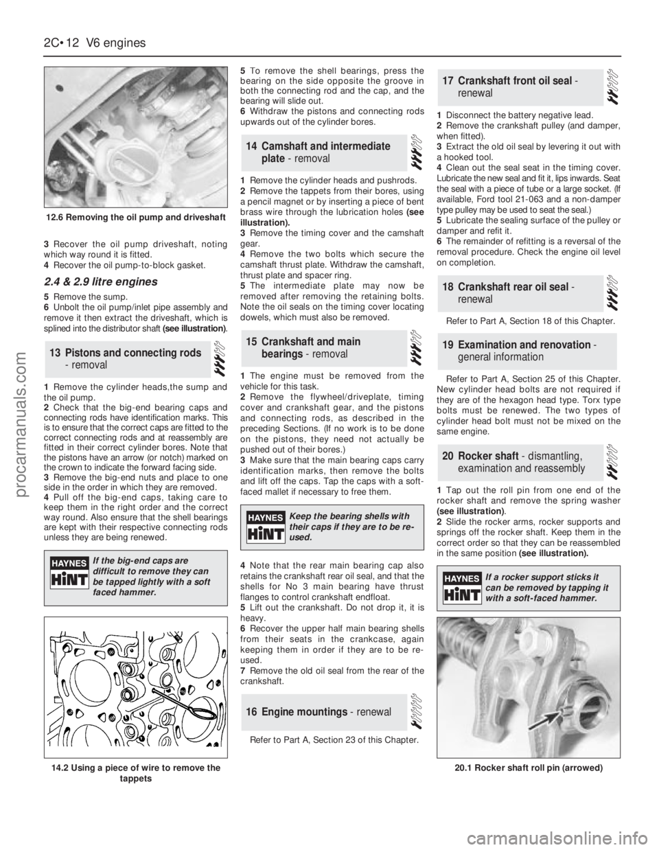
remove it then extract the driveshaft, which is
splined into the distributor shaft (see illustration).
1Remove the cylinder heads,the sump and
the oil pump.
2Check that the big-end bearing caps and
connecting rods have identification marks. This
is to ensure that the correct caps are fitted to the
correct connecting rods and at reassembly are
fitted in their correct cylinder bores. Note that
the pistons have an arrow (or notch) marked on
the crown to indicate the forward facing side.
3Remove the big-end nuts and place to one
side in the order in which they are removed.
4Pull off the big-end caps, taking care to
keep them in the right order and the correct
way round. Also ensure that the shell bearings
are kept with their respective connecting rods
unless they are being renewed.5To remove the shell bearings, press the
bearing on the side opposite the groove in
both the connecting rod and the cap, and the
bearing will slide out.
6Withdraw the pistons and connecting rods
upwards out of the cylinder bores.
1Remove the cylinder heads and pushrods.
2Remove the tappets from their bores, using
a pencil magnet or by inserting a piece of bent
brass wire through the lubrication holes (see
illustration).
3Remove the timing cover and the camshaft
gear.
4Remove the two bolts which secure the
camshaft thrust plate. Withdraw the camshaft,
thrust plate and spacer ring.
5The intermediate plate may now be
removed after removing the retaining bolts.
Note the oil seals on the timing cover locating
dowels, which must also be removed.
1The engine must be removed from the
vehicle for this task.
2Remove the flywheel/driveplate, timing
cover and crankshaft gear, and the pistons
and connecting rods, as described in the
preceding Sections. (If no work is to be done
on the pistons, they need not actually be
pushed out of their bores.)
3Make sure that the main bearing caps carry
identification marks, then remove the bolts
and lift off the caps. Tap the caps with a soft-
faced mallet if necessary to free them.
4Note that the rear main bearing cap also
retains the crankshaft rear oil seal, and that the
shells for No 3 main bearing have thrust
flanges to control crankshaft endfloat.
5Lift out the crankshaft. Do not drop it, it is
heavy.
6Recover the upper half main bearing shells
from their seats in the crankcase, again
keeping them in order if they are to be re-
used.
7Remove the old oil seal from the rear of the
crankshaft.
Refer to Part A, Section 23 of this Chapter.1Disconnect the battery negative lead.
2Remove the crankshaft pulley (and damper,
when fitted).
3Extract the old oil seal by levering it out with
a hooked tool.
4Clean out the seal seat in the timing cover.
Lubricate the new seal and fit it, lips inwards. Seat
the seal with a piece of tube or a large socket. (If
available, Ford tool 21-063 and a non-damper
type pulley may be used to seat the seal.)
5Lubricate the sealing surface of the pulley or
damper and refit it.
6The remainder of refitting is a reversal of the
removal procedure. Check the engine oil level
on completion.
Refer to Part A, Section 18 of this Chapter.
Refer to Part A, Section 25 of this Chapter.
New cylinder head bolts are not required if
they are of the hexagon head type. Torx type
bolts must be renewed. The two types of
cylinder head bolt must not be mixed on the
same engine.
1Tap out the roll pin from one end of the
rocker shaft and remove the spring washer
(see illustration).
2Slide the rocker arms, rocker supports and
springs off the rocker shaft. Keep them in the
correct order so that they can be reassembled
in the same position (see illustration).
20Rocker shaft - dismantling,
examination and reassembly
19Examination and renovation -
general information
18Crankshaft rear oil seal -
renewal
17Crankshaft front oil seal -
renewal
16Engine mountings - renewal
15Crankshaft and main
bearings - removal
14Camshaft and intermediate
plate - removal
13Pistons and connecting rods
- removal
2C•12V6 engines
12.6 Removing the oil pump and driveshaft
20.1 Rocker shaft roll pin (arrowed)14.2 Using a piece of wire to remove the
tappets
If the big-end caps are
difficult to remove they can
be tapped lightly with a soft
faced hammer.
Keep the bearing shells with
their caps if they are to be re-
used.
If a rocker support sticks it
can be removed by tapping it
with a soft-faced hammer.
procarmanuals.com