1985 FORD GRANADA ESP
[x] Cancel search: ESPPage 184 of 255
Estate
19This procedure is the same as described
above for the Saloon models noting that it is
necessary to remove the luggage
compartment side trim panel to gain access to
the light cluster retaining nuts.
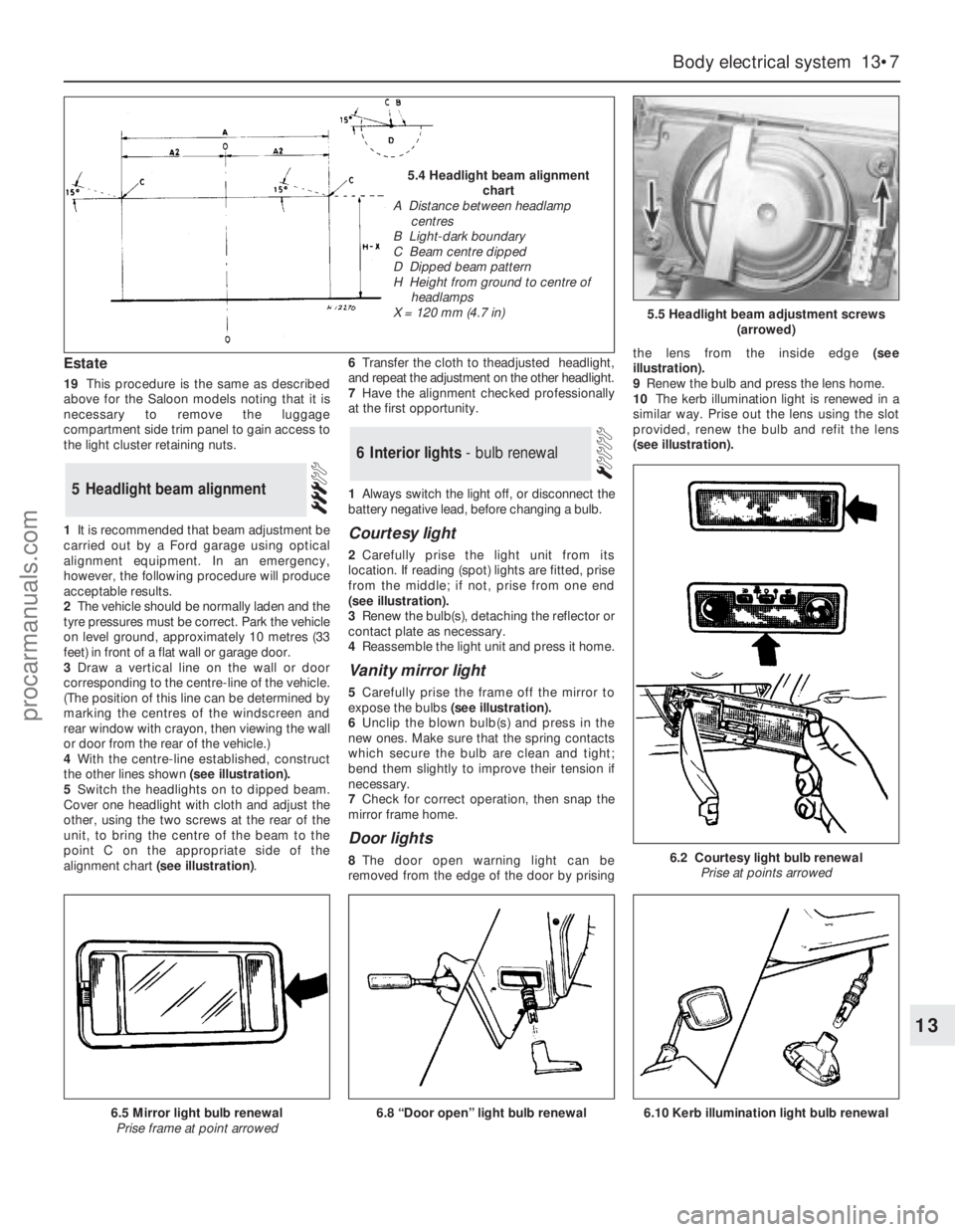
1It is recommended that beam adjustment be
carried out by a Ford garage using optical
alignment equipment. In an emergency,
however, the following procedure will produce
acceptable results.
2The vehicle should be normally laden and the
tyre pressures must be correct. Park the vehicle
on level ground, approximately 10 metres (33
feet) in front of a flat wall or garage door.
3Draw a vertical line on the wall or door
corresponding to the centre-line of the vehicle.
(The position of this line can be determined by
marking the centres of the windscreen and
rear window with crayon, then viewing the wall
or door from the rear of the vehicle.)
4With the centre-line established, construct
the other lines shown (see illustration).
5Switch the headlights on to dipped beam.
Cover one headlight with cloth and adjust the
other, using the two screws at the rear of the
unit, to bring the centre of the beam to the
point C on the appropriate side of the
alignment chart (see illustration).6Transfer the cloth to theadjusted headlight,
and repeat the adjustment on the other headlight.
7Have the alignment checked professionally
at the first opportunity.
1Always switch the light off, or disconnect the
battery negative lead, before changing a bulb.
Courtesy light
2Carefully prise the light unit from its
location. If reading (spot) lights are fitted, prise
from the middle; if not, prise from one end
(seeillustration).
3Renew the bulb(s), detaching the reflector or
contact plate as necessary.
4Reassemble the light unit and press it home.
Vanity mirror light
5Carefully prise the frame off the mirror to
expose the bulbs(see illustration).
6Unclip the blown bulb(s) and press in the
new ones. Make sure that the spring contacts
which secure the bulb are clean and tight;
bend them slightly to improve their tension if
necessary.
7Check for correct operation, then snap the
mirror frame home.
Door lights
8The door open warning light can be
removed from the edge of the door by prisingthe lens from the inside edge (see
illustration).
9Renew the bulb and press the lens home.
10The kerb illumination light is renewed in a
similar way. Prise out the lens using the slot
provided, renew the bulb and refit the lens
(seeillustration).
6Interior lights - bulb renewal
5Headlight beam alignment
Body electrical system 13•7
13
5.5 Headlight beam adjustment screws
(arrowed)
6.2 Courtesy light bulb renewal
Prise at points arrowed
6.8 “Door open” light bulb renewal6.5 Mirror light bulb renewal
Prise frame at point arrowed
5.4 Headlight beam alignment
chart
A Distance between headlamp
centres
B Light-dark boundary
C Beam centre dipped
D Dipped beam pattern
H Height from ground to centre of
headlamps
X = 120 mm (4.7 in)
6.10 Kerb illumination light bulb renewal
procarmanuals.com
Page 194 of 255
Estate
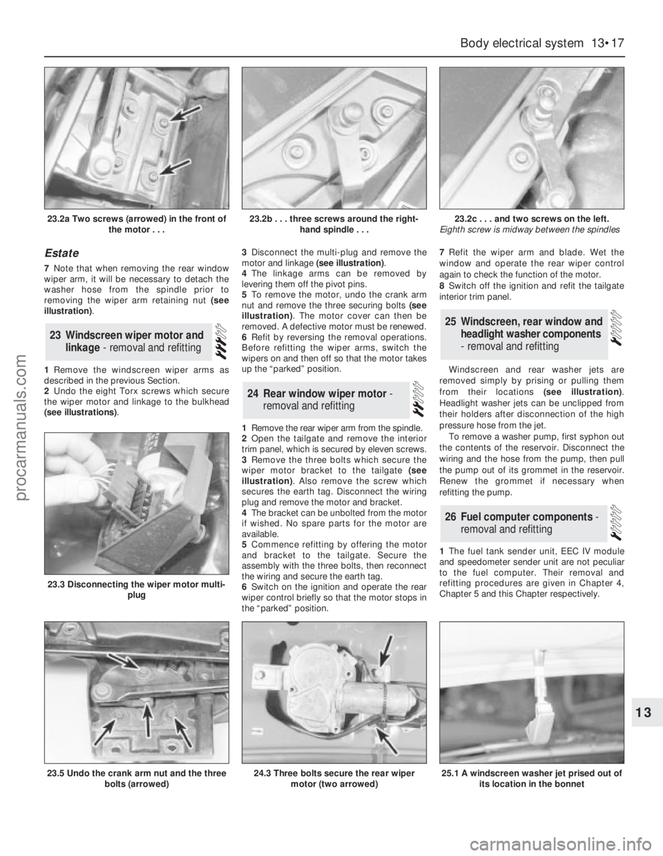
7Note that when removing the rear window
wiper arm, it will be necessary to detach the
washer hose from the spindle prior to
removing the wiper arm retaining nut (see
illustration).
1Remove the windscreen wiper arms as
described in the previous Section.
2Undo the eight Torx screws which secure
the wiper motor and linkage to the bulkhead
(see illustrations).3Disconnect the multi-plug and remove the
motor and linkage (see illustration).
4The linkage arms can be removed by
levering them off the pivot pins.
5To remove the motor, undo the crank arm
nut and remove the three securing bolts (see
illustration). The motor cover can then be
removed. A defective motor must be renewed.
6Refit by reversing the removal operations.
Before refitting the wiper arms, switch the
wipers on and then off so that the motor takes
up the “parked” position.
1Remove the rear wiper arm from the spindle.
2Open the tailgate and remove the interior
trim panel, which is secured by eleven screws.
3Remove the three bolts which secure the
wiper motor bracket to the tailgate (see
illustration). Also remove the screw which
secures the earth tag. Disconnect the wiring
plug and remove the motor and bracket.
4The bracket can be unbolted from the motor
if wished. No spare parts for the motor are
available.
5Commence refitting by offering the motor
and bracket to the tailgate. Secure the
assembly with the three bolts, then reconnect
the wiring and secure the earth tag.
6Switch on the ignition and operate the rear
wiper control briefly so that the motor stops in
the “parked” position.7Refit the wiper arm and blade. Wet the
window and operate the rear wiper control
again to check the function of the motor.
8Switch off the ignition and refit the tailgate
interior trim panel.
Windscreen and rear washer jets are
removed simply by prising or pulling them
from their locations (see illustration).
Headlight washer jets can be unclipped from
their holders after disconnection of the high
pressure hose from the jet.
To remove a washer pump, first syphon out
the contents of the reservoir. Disconnect the
wiring and the hose from the pump, then pull
the pump out of its grommet in the reservoir.
Renew the grommet if necessary when
refitting the pump.
1The fuel tank sender unit, EEC IV module
and speedometer sender unit are not peculiar
to the fuel computer. Their removal and
refitting procedures are given in Chapter 4,
Chapter 5 and this Chapter respectively.
26Fuel computer components -
removal and refitting
25Windscreen, rear window and
headlight washer components
- removal and refitting
24Rear window wiper motor -
removal and refitting
23Windscreen wiper motor and
linkage - removal and refitting
Body electrical system 13•17
13
23.2a Two screws (arrowed) in the front of
the motor . . .23.2b . . . three screws around the right-
hand spindle . . .23.2c . . . and two screws on the left.
Eighth screw is midway between the spindles
23.5 Undo the crank arm nut and the three
bolts (arrowed)
23.3 Disconnecting the wiper motor multi-
plug
24.3 Three bolts secure the rear wiper
motor (two arrowed)25.1 A windscreen washer jet prised out of
its location in the bonnet
procarmanuals.com
Page 241 of 255
REF•6
Engine fails to rotate when attempting to start
m mBattery terminal connections loose or corroded (Chapter 1).
m mBattery discharged or faulty (Chapter 5).
m mBroken, loose or disconnected wiring in the starting circuit
(Chapter 5).
m mDefective starter solenoid or switch (Chapter 5).
m mDefective starter motor (Chapter 5).
m mStarter pinion or flywheel/driveplate ring gear teeth loose or broken
(Chapters 2 or 5).
m mEngine earth strap broken or disconnected.
Starter motor turns engine slowly
m
mPartially-discharged battery (recharge, use jump leads, or push
start) (Chapter 5).
m mBattery terminals loose or corroded (Chapter 1).
m mBattery earth to body defective (Chapter 5).
m mEngine earth strap loose.
m mStarter motor (or solenoid) wiring loose (Chapter 5).
m mStarter motor internal fault (Chapter 5).
Engine rotates, but will not start
m
mFuel pump inertia switch tripped (electric pump) (Chapter 4).
m mFuel tank empty.
m mBattery discharged (engine rotates slowly) (Chapter 5).
m mBattery terminal connections loose or corroded (Chapter 1).
m mIgnition components damp or damaged (Chapters 1 and 5).
m mBroken, loose or disconnected wiring in the ignition circuit
(Chapters 1 and 5).
m mWorn, faulty or incorrectly-gapped spark plugs (Chapter 1).
m mFuel injection system fault (Chapter 4).
m mMajor mechanical failure (eg broken timing chain) (Chapter 2).
Engine difficult to start when cold
m
mBattery discharged (Chapter 5).
m mBattery terminal connections loose or corroded (Chapter 1).
m mWorn, faulty or incorrectly-gapped spark plugs (Chapter 1).
m mFuel injection system fault (Chapter 4).
m mOther ignition system fault (Chapters 1 and 5).
m mLow cylinder compressions (Chapter 2).
Engine difficult to start when hot
m
mAir filter element dirty or clogged (Chapter 1).
m mFuel injection system fault (Chapter 4).
m mLow cylinder compressions (Chapter 2).
Starter motor noisy or excessively-rough in
engagement
m mStarter pinion or flywheel/driveplate ring gear teeth loose or broken
(Chapters 2 or 5).
m mStarter motor mounting bolts loose or missing (Chapter 5).
m mStarter motor internal components worn or damaged (Chapter 5).
Engine starts, but stops immediately
m
mLoose or faulty electrical connections in the ignition circuit
(Chapters 1 and 5).
m mVacuum leak at the throttle body or inlet manifold (Chapter 4).
m mFuel injection system fault (Chapter 4).
Engine idles erratically
m
mCarburettor stepper motor plunger dirty (2.0 litre only) (Chapter 5)
m mIncorrectly-adjusted idle speed (Chapter 4).
m mAir filter element clogged (Chapter 1).
m mVacuum leak at the throttle body, inlet manifold or associated hoses
(Chapter 4).
m mWorn, faulty or incorrectly-gapped spark plugs (Chapter 1).
m mUneven or low cylinder compressions (Chapter 2).
m mCamshaft lobes worn (Chapter 2).
m mFuel injection system fault (Chapter 4).
Engine misfires at idle speed
m
mWorn, faulty or incorrectly-gapped spark plugs (Chapter 1).
m mFaulty spark plug HT leads (Chapter 5).
m mVacuum leak at the throttle body, inlet manifold or associated hoses
(Chapter 4).
m mFuel injection system fault (Chapter 4).
m mDistributor cap cracked or tracking internally, where applicable
(Chapter 5).
m mUneven or low cylinder compressions (Chapter 2).
m mDisconnected, leaking, or perished crankcase ventilation hoses
(Chapter 4).
Fault Finding
spark plugs may only be pointers to some underlying fault.
The pages which follow provide an easy-reference guide to the more
common problems which may occur during the operation of the
vehicle. These problems and their possible causes are grouped under
headings denoting various components or systems, such as Engine,
Cooling system, etc. The Chapter and/or Section which deals with the
problem is also shown in brackets. Whatever the fault, certain basic
principles apply. These are as follows:
Verify the fault. This is simply a matter of being sure that you know
what the symptoms are before starting work. This is particularly
important if you are investigating a fault for someone else, who may
not have described it very accurately.
Don’t overlook the obvious. For example, if the vehicle won’t start, is
there fuel in the tank? (Don’t take anyone else’s word on this particular
point, and don’t trust the fuel gauge either!) If an electrical fault isindicated, look for loose or broken wires before digging out the test
gear.
Cure the disease, not the symptom. Substituting a flat battery with a
fully-charged one will get you off the hard shoulder, but if the
underlying cause is not attended to, the new battery will go the same
way. Similarly, changing oil-fouled spark plugs for a new set will get
you moving again, but remember that the reason for the fouling (if it
wasn’t simply an incorrect grade of plug) will have to be established
and corrected.
Don’t take anything for granted. Particularly, don’t forget that a
“new” component may itself be defective (especially if it’s been rattling
around in the boot for months), and don’t leave components out of a
fault diagnosis sequence just because they are new or recently-fitted.
When you do finally diagnose a difficult fault, you’ll probably realise
that all the evidence was there from the start.
1 Engine
procarmanuals.com
Page 249 of 255
REF•14Glossary of Technical Terms
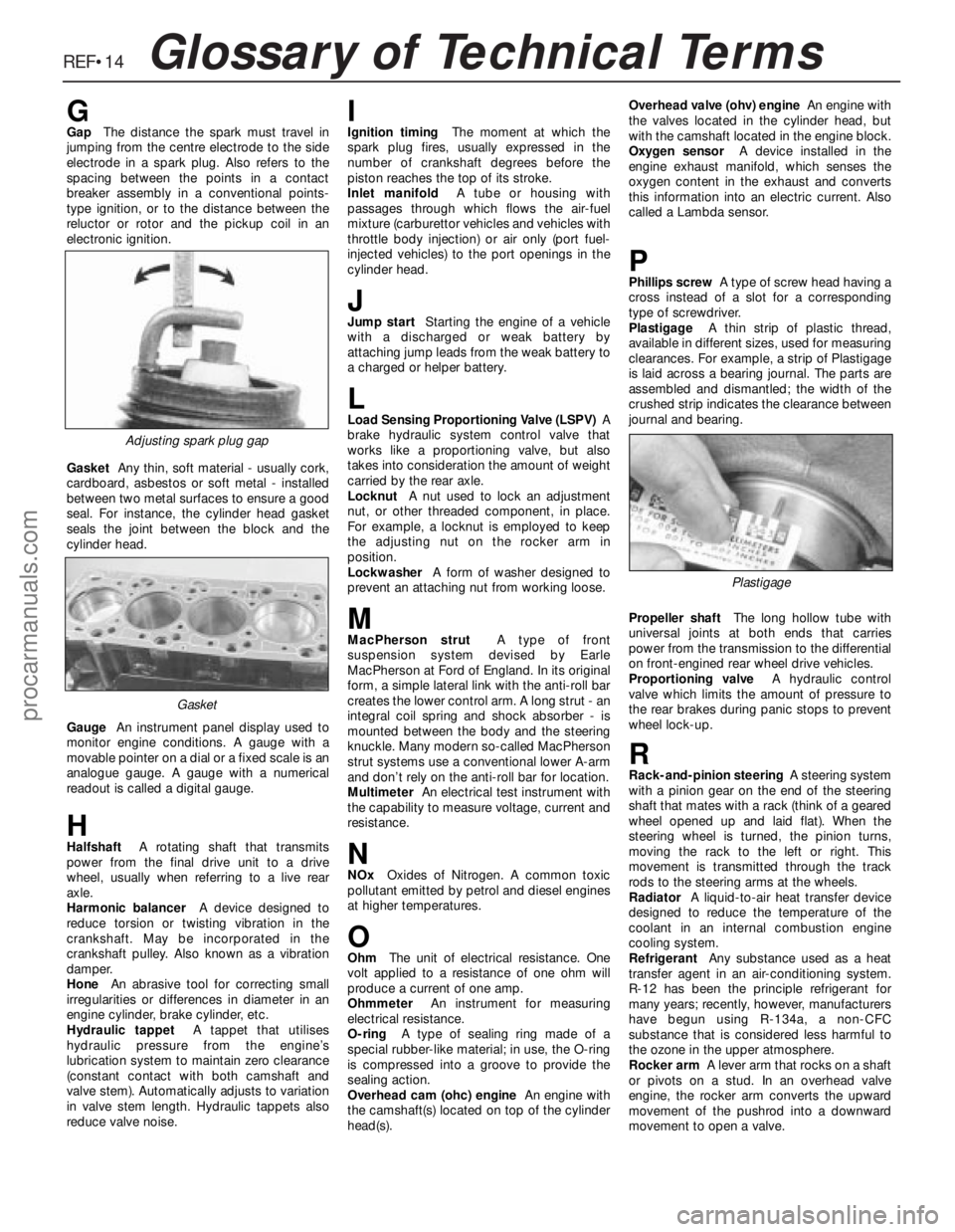
GGapThe distance the spark must travel in
jumping from the centre electrode to the side
electrode in a spark plug. Also refers to the
spacing between the points in a contact
breaker assembly in a conventional points-
type ignition, or to the distance between the
reluctor or rotor and the pickup coil in an
electronic ignition.
GasketAny thin, soft material - usually cork,
cardboard, asbestos or soft metal - installed
between two metal surfaces to ensure a good
seal. For instance, the cylinder head gasket
seals the joint between the block and the
cylinder head.
GaugeAn instrument panel display used to
monitor engine conditions. A gauge with a
movable pointer on a dial or a fixed scale is an
analogue gauge. A gauge with a numerical
readout is called a digital gauge.
HHalfshaftA rotating shaft that transmits
power from the final drive unit to a drive
wheel, usually when referring to a live rear
axle.
Harmonic balancerA device designed to
reduce torsion or twisting vibration in the
crankshaft. May be incorporated in the
crankshaft pulley. Also known as a vibration
damper.
HoneAn abrasive tool for correcting small
irregularities or differences in diameter in an
engine cylinder, brake cylinder, etc.
Hydraulic tappetA tappet that utilises
hydraulic pressure from the engine’s
lubrication system to maintain zero clearance
(constant contact with both camshaft and
valve stem). Automatically adjusts to variation
in valve stem length. Hydraulic tappets also
reduce valve noise.
IIgnition timingThe moment at which the
spark plug fires, usually expressed in the
number of crankshaft degrees before the
piston reaches the top of its stroke.
Inlet manifoldA tube or housing with
passages through which flows the air-fuel
mixture (carburettor vehicles and vehicles with
throttle body injection) or air only (port fuel-
injected vehicles) to the port openings in the
cylinder head.
JJump startStarting the engine of a vehicle
with a discharged or weak battery by
attaching jump leads from the weak battery to
a charged or helper battery.
LLoad Sensing Proportioning Valve (LSPV)A
brake hydraulic system control valve that
works like a proportioning valve, but also
takes into consideration the amount of weight
carried by the rear axle.
LocknutA nut used to lock an adjustment
nut, or other threaded component, in place.
For example, a locknut is employed to keep
the adjusting nut on the rocker arm in
position.
LockwasherA form of washer designed to
prevent an attaching nut from working loose.
MMacPherson strutA type of front
suspension system devised by Earle
MacPherson at Ford of England. In its original
form, a simple lateral link with the anti-roll bar
creates the lower control arm. A long strut - an
integral coil spring and shock absorber - is
mounted between the body and the steering
knuckle. Many modern so-called MacPherson
strut systems use a conventional lower A-arm
and don’t rely on the anti-roll bar for location.
MultimeterAn electrical test instrument with
the capability to measure voltage, current and
resistance.
NNOxOxides of Nitrogen. A common toxic
pollutant emitted by petrol and diesel engines
at higher temperatures.
OOhmThe unit of electrical resistance. One
volt applied to a resistance of one ohm will
produce a current of one amp.
OhmmeterAn instrument for measuring
electrical resistance.
O-ringA type of sealing ring made of a
special rubber-like material; in use, the O-ring
is compressed into a groove to provide the
sealing action.
Overhead cam (ohc) engineAn engine with
the camshaft(s) located on top of the cylinder
head(s).Overhead valve (ohv) engineAn engine with
the valves located in the cylinder head, but
with the camshaft located in the engine block.
Oxygen sensorA device installed in the
engine exhaust manifold, which senses the
oxygen content in the exhaust and converts
this information into an electric current. Also
called a Lambda sensor.
PPhillips screwA type of screw head having a
cross instead of a slot for a corresponding
type of screwdriver.
PlastigageA thin strip of plastic thread,
available in different sizes, used for measuring
clearances. For example, a strip of Plastigage
is laid across a bearing journal. The parts are
assembled and dismantled; the width of the
crushed strip indicates the clearance between
journal and bearing.
Propeller shaftThe long hollow tube with
universal joints at both ends that carries
power from the transmission to the differential
on front-engined rear wheel drive vehicles.
Proportioning valveA hydraulic control
valve which limits the amount of pressure to
the rear brakes during panic stops to prevent
wheel lock-up.
RRack-and-pinion steeringA steering system
with a pinion gear on the end of the steering
shaft that mates with a rack (think of a geared
wheel opened up and laid flat). When the
steering wheel is turned, the pinion turns,
moving the rack to the left or right. This
movement is transmitted through the track
rods to the steering arms at the wheels.
RadiatorA liquid-to-air heat transfer device
designed to reduce the temperature of the
coolant in an internal combustion engine
cooling system.
RefrigerantAny substance used as a heat
transfer agent in an air-conditioning system.
R-12 has been the principle refrigerant for
many years; recently, however, manufacturers
have begun using R-134a, a non-CFC
substance that is considered less harmful to
the ozone in the upper atmosphere.
Rocker armA lever arm that rocks on a shaft
or pivots on a stud. In an overhead valve
engine, the rocker arm converts the upward
movement of the pushrod into a downward
movement to open a valve.
Adjusting spark plug gap
Plastigage
Gasket
procarmanuals.com
Page 254 of 255
Q
Quarter window moulding - 12•10
R
Radiator - 3•3, 12•9
Radio fader light - 13•8
Radio or radio/cassette player - 13•20, 13•21
Rear light cluster - 13•5, 13•6
Recline motor - 13•15
Regulator mechanism - 12•9
Relays - 13•13
Respraying - 12•3
Reversing light switch - 7B•3, 13•12, 13•13
Ride height control - 11•12, 11•13
Road test - 1•16
Rocker shaft - 2C•12
Rotor arm - 5•5
Routine maintenance and servicing- 1•1et
seq
Rust holes or gashes in bodywork - 12•2
S
Safety first! - 0•5
Scalding - 0•5
Scratches in bodywork - 12•2
Screw threads and fastenings - REF•4
Seals and hoses - 1•19
Seat air cushion - 12•17
Seat belts - 0•12, 1•10, 12•17, 12•18
Seats - 0•12, 12•17, 12•18, 13•10, 13•13,
13•15
Selector rod - 7B•4
Servo - 10•12, 10•13, 13•20
Shock absorbers - 0•12, 0•13, 11•12
Short-circuit - 13•4
Side mouldings - 12•10
Sidelight - 13•4
Sliding roof - 12•5, 13•12, 13•16
Spare parts - 0•8
Spark plugs - 1•12, 5•5
Speakers - 13•21, 13•22
Speed control system components - 13•19,
13•20
Speedometer sender unit - 13•16
Spoiler - 12•11
Springs - 0•13, 11•11
Starter inhibitor/reversing light switch -
7B•3, 13•13
Starter motor - 5•4, 5•5
Starter motor noisy or excessively-rough in
engagement - REF•6
Starter motor turns engine slowly - REF•6
Steering and suspension - 0•12, 0•13, 1•15,
1•16, 11•1et seq,REF•10
Steering column- 0•11, 11•5
Steering gear - 11•3
Steering intermediate shaft and flexible
coupling - 11•6Steering play - REF•10
Steering rack bellows - 11•4
Steering stiff - REF•10
Steering wheel - 0•11, 11•4, 11•5
Steering wheel and column -
Stop-light switch - 13•12
Strut - 11•9, 11•10
Stub axle carrier - 11•7
Sump - 2A•9, 2A•16, 2B•15, 2C•9, 2C•19
Switch illumination lights - 13•8
Switches - 13•9, 13•11, 13•12, 13•13,
13•18, 13•19
T
Tailgate - 12•4, 12•7, 13•12, 13•18
Tailgate wash/wipe inoperative, or
unsatisfactory in operation - REF•11
Tailgate window mouldings - 12•10
Tappets - 2C•13
Temperature gauge gives false reading -
REF•11
Temperature gauge sender - 3•7
Thermostat - 3•3
Throttle body - 4•15
Throttle cable - 4•7
Throttle kicker - 4•13
Throttle pedal - 4•6
Throttle position sensor - 4•15
Timing belt - 2A•8, 2A•14, 2A•18
Timing chain - 2B•8, 2B•10, 2C•9, 2C•17
Tools and working facilities- REF•1et seq
Towing - 0•7
Track rod end - 11•6
Transmission fluid brown, or has burned
smell - REF•9
Transmission slips, shifts roughly, is noisy,
or has no drive in forward or reverse
gears - REF•9
Transmission will not downshift (kickdown)
with accelerator pedal fully depressed -
REF•9
Tyre wear - REF•10
Tyres - 0•14, 1•7
U
Ultrasonic sensor - 13•23
Underbody inspection - 1•15
Unleaded fuel - 4•23
V
Vacuum dump valve/switch - 13•19
Vacuum hoses - 2C•7
Vacuum line modification - 7B•4
Vacuum pull-down adjustment - 4•13
Vacuum pump - 13•20
Vacuum servo - 10•12, 10•13, 13•20
Valve block and pump assembly - 10•13
Valve clearances - 1•13, 2A•20, 2C•21Valve grinding - 2A•14
Vane airflow meter(s) - 4•16
Vanity mirror light - 13•7
Vapour separator - 4•7
Vehicle identification - 0•9, 0•12
Vehicle pulls to one side - REF•9, REF•10
Vehicle speed sensor - 5•12
Vibration damper (MT75type gearbox) - 8•4
Viscous-coupled fan - 3•5
W
Wandering or general instability - REF•10
Warning light bulbs - 13•18
Wash/wipe inoperative, or unsatisfactory in
operation - REF•11
Wash/wipe switch - 13•12
Washer fluid - 1•7, 13•19
Washer jets inoperative - REF•11
Washer pump fails to operate - REF•11
Washer pump runs for some time before
fluid is emitted from jets - REF•11
Water pump - 3•5
Water pump/alternator drivebelt - 3•7
Weatherstrip - 12•7
Weber 2V carburettor - 4•9, 4•10
Weber 2V TLD carburettor - 4•11, 4•12,
4•13
Wheel alignment - 11•7
Wheel bearings - 0•13, 11•8, 11•11
Wheel changing - 0•7
Wheel sensors - 10•12
Wheel stud - 11•11
Wheel wobble and vibration - REF•10
Wheels - 0•14, 1•10
Wheels locking under normal braking -
REF•10
Window frame mouldings - 12•10
Window glass - 12•8
Window glass fails to move - REF•11
Window glass slow to move - REF•11
Window glass will only move in one
direction - REF•11
Window operating motor - 13•15
Window operating switch - 13•12
Windscreen - 0•11, 12•9
Windscreen mouldings - 12•10
Windscreen, rear window and headlight
washer components - 13•17
Wiper arms and blades - 13•16
Wiper blades - 1•9
Wiper blades fail to clean the glass
effectively - REF•11
Wiper blades sweep over too large or too
small an area of the glass - REF•11
Wiper motor - 13•17
Wipers fail to operate, or operate very
slowly - REF•11
Wiring diagrams- WD•0 et seq
Working facilities - REF•3
IND•3Index
procarmanuals.com