1985 FORD GRANADA display
[x] Cancel search: displayPage 185 of 255
Footwell lights
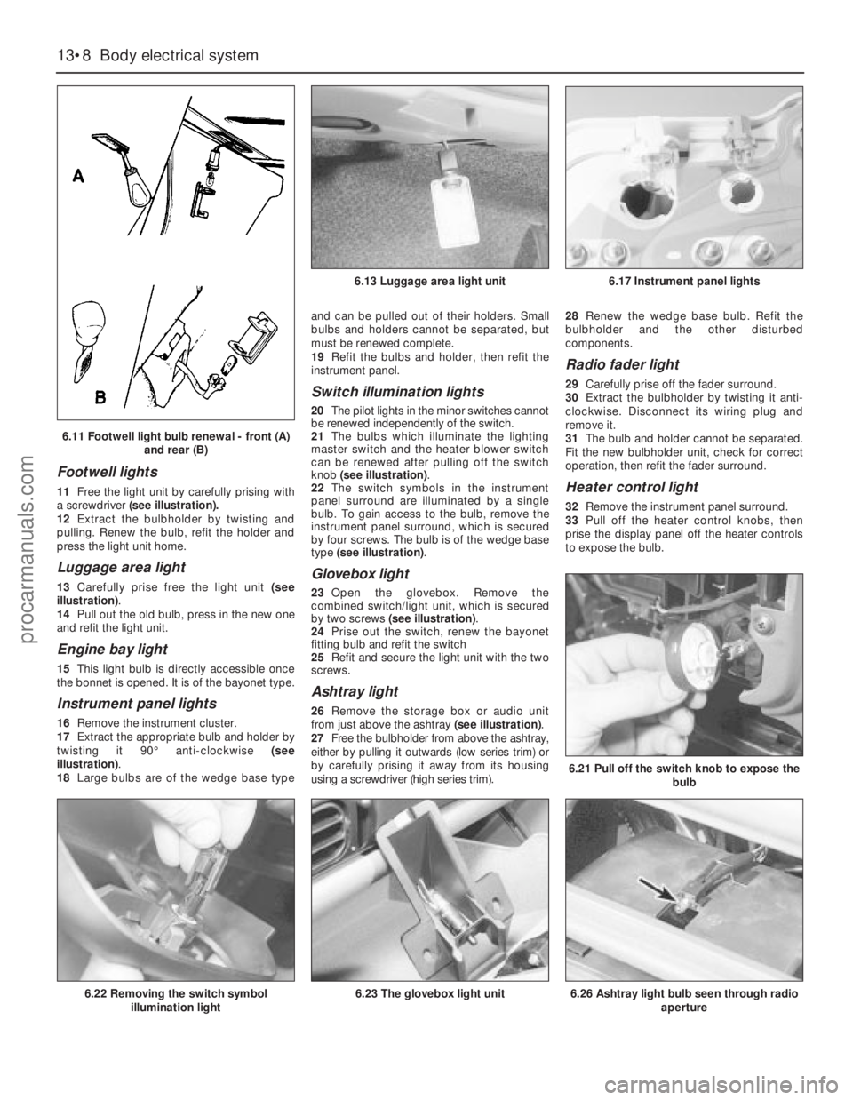
11Free the light unit by carefully prising with
a screwdriver(see illustration).
12Extract the bulbholder by twisting and
pulling. Renew the bulb, refit the holder and
press the light unit home.
Luggage area light
13Carefully prise free the light unit (see
illustration).
14Pull out the old bulb, press in the new one
and refit the light unit.
Engine bay light
15This light bulb is directly accessible once
the bonnet is opened. It is of the bayonet type.
Instrument panel lights
16Remove the instrument cluster.
17Extract the appropriate bulb and holder by
twisting it 90°anti-clockwise (see
illustration).
18Large bulbs are of the wedge base typeand can be pulled out of their holders. Small
bulbs and holders cannot be separated, but
must be renewed complete.
19Refit the bulbs and holder, then refit the
instrument panel.
Switch illumination lights
20The pilot lights in the minor switches cannot
be renewed independently of the switch.
21The bulbs which illuminate the lighting
master switch and the heater blower switch
can be renewed after pulling off the switch
knob (see illustration).
22The switch symbols in the instrument
panel surround are illuminated by a single
bulb. To gain access to the bulb, remove the
instrument panel surround, which is secured
by four screws. The bulb is of the wedge base
type (see illustration).
Glovebox light
23Open the glovebox. Remove the
combined switch/light unit, which is secured
by two screws (see illustration).
24Prise out the switch, renew the bayonet
fitting bulb and refit the switch
25Refit and secure the light unit with the two
screws.
Ashtray light
26Remove the storage box or audio unit
from just above the ashtray (see illustration).
27Free the bulbholder from above the ashtray,
either by pulling it outwards (low series trim) or
by carefully prising it away from its housing
using a screwdriver (high series trim).28Renew the wedge base bulb. Refit the
bulbholder and the other disturbed
components.
Radio fader light
29Carefully prise off the fader surround.
30Extract the bulbholder by twisting it anti-
clockwise. Disconnect its wiring plug and
remove it.
31The bulb and holder cannot be separated.
Fit the new bulbholder unit, check for correct
operation, then refit the fader surround.
Heater control light
32Remove the instrument panel surround.
33Pull off the heater control knobs, then
prise the display panel off the heater controls
to expose the bulb.
13•8Body electrical system
6.21 Pull off the switch knob to expose the
bulb
6.26 Ashtray light bulb seen through radio
aperture6.22 Removing the switch symbol
illumination light6.23 The glovebox light unit
6.13 Luggage area light unit6.17 Instrument panel lights
6.11 Footwell light bulb renewal - front (A)
and rear (B)
procarmanuals.com
Page 186 of 255
34Renew the bulb, check for correct
operation, then refit the disturbed components
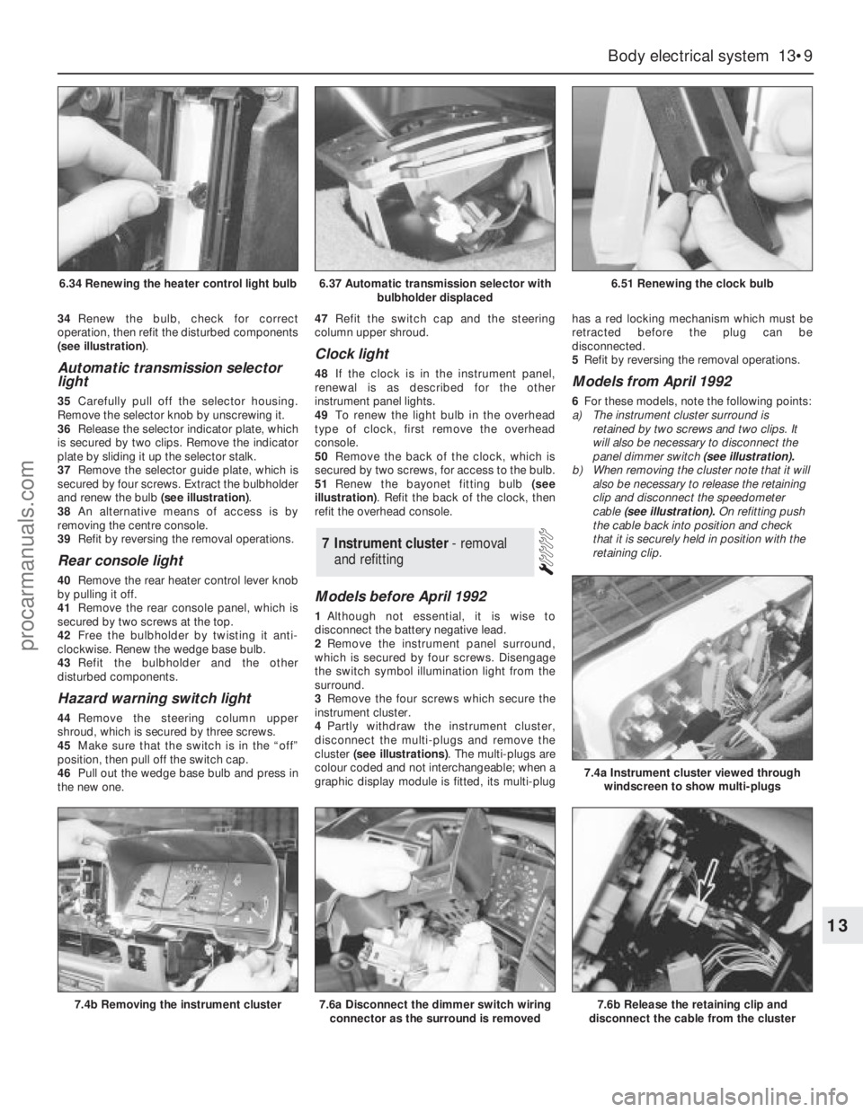
(see illustration).
Automatic transmission selector
light
35Carefully pull off the selector housing.
Remove the selector knob by unscrewing it.
36Release the selector indicator plate, which
is secured by two clips. Remove the indicator
plate by sliding it up the selector stalk.
37Remove the selector guide plate, which is
secured by four screws. Extract the bulbholder
and renew the bulb (see illustration).
38An alternative means of access is by
removing the centre console.
39Refit by reversing the removal operations.
Rear console light
40Remove the rear heater control lever knob
by pulling it off.
41Remove the rear console panel, which is
secured by two screws at the top.
42Free the bulbholder by twisting it anti-
clockwise. Renew the wedge base bulb.
43Refit the bulbholder and the other
disturbed components.
Hazard warning switch light
44Remove the steering column upper
shroud, which is secured by three screws.
45Make sure that the switch is in the “off”
position, then pull off the switch cap.
46Pull out the wedge base bulb and press in
the new one.47Refit the switch cap and the steering
column upper shroud.
Clock light
48If the clock is in the instrument panel,
renewal is as described for the other
instrument panel lights.
49To renew the light bulb in the overhead
type of clock, first remove the overhead
console.
50Remove the back of the clock, which is
secured by two screws, for access to the bulb.
51Renew the bayonet fitting bulb (see
illustration). Refit the back of the clock, then
refit the overhead console.
Models before April 1992
1Although not essential, it is wise to
disconnect the battery negative lead.
2Remove the instrument panel surround,
which is secured by four screws. Disengage
the switch symbol illumination light from the
surround.
3Remove the four screws which secure the
instrument cluster.
4Partly withdraw the instrument cluster,
disconnect the multi-plugs and remove the
cluster (see illustrations). The multi-plugs are
colour coded and not interchangeable; when a
graphic display module is fitted, its multi-plughas a red locking mechanism which must be
retracted before the plug can be
disconnected.
5Refit by reversing the removal operations.
Models from April 1992
6For these models, note the following points:
a)The instrument cluster surround is
retained by two screws and two clips. It
will also be necessary to disconnect the
panel dimmer switch (see illustration).
b)When removing the cluster note that it will
also be necessary to release the retaining
clip and disconnect the speedometer
cable (see illustration).On refitting push
the cable back into position and check
that it is securely held in position with the
retaining clip.
7Instrument cluster - removal
and refitting
Body electrical system 13•9
13
6.37 Automatic transmission selector with
bulbholder displaced6.51 Renewing the clock bulb
7.4b Removing the instrument cluster7.6a Disconnect the dimmer switch wiring
connector as the surround is removed7.6b Release the retaining clip and
disconnect the cable from the cluster
7.4a Instrument cluster viewed through
windscreen to show multi-plugs
6.34 Renewing the heater control light bulb
procarmanuals.com
Page 187 of 255
1With the instrument cluster removed, a
particular gauge or other component can be
renewed by following the appropriate parts of
this Section.
2Remove all the light bulbs and holders from
the rear of the panel by twisting them anti-
clockwise.
3To remove the printed circuit, unclip and
remove the two multi-plug terminal retainers.
Remove all the nuts and washers from the
printed circuit terminals, then unclip and
remove the printed circuit. Be careful with it, it
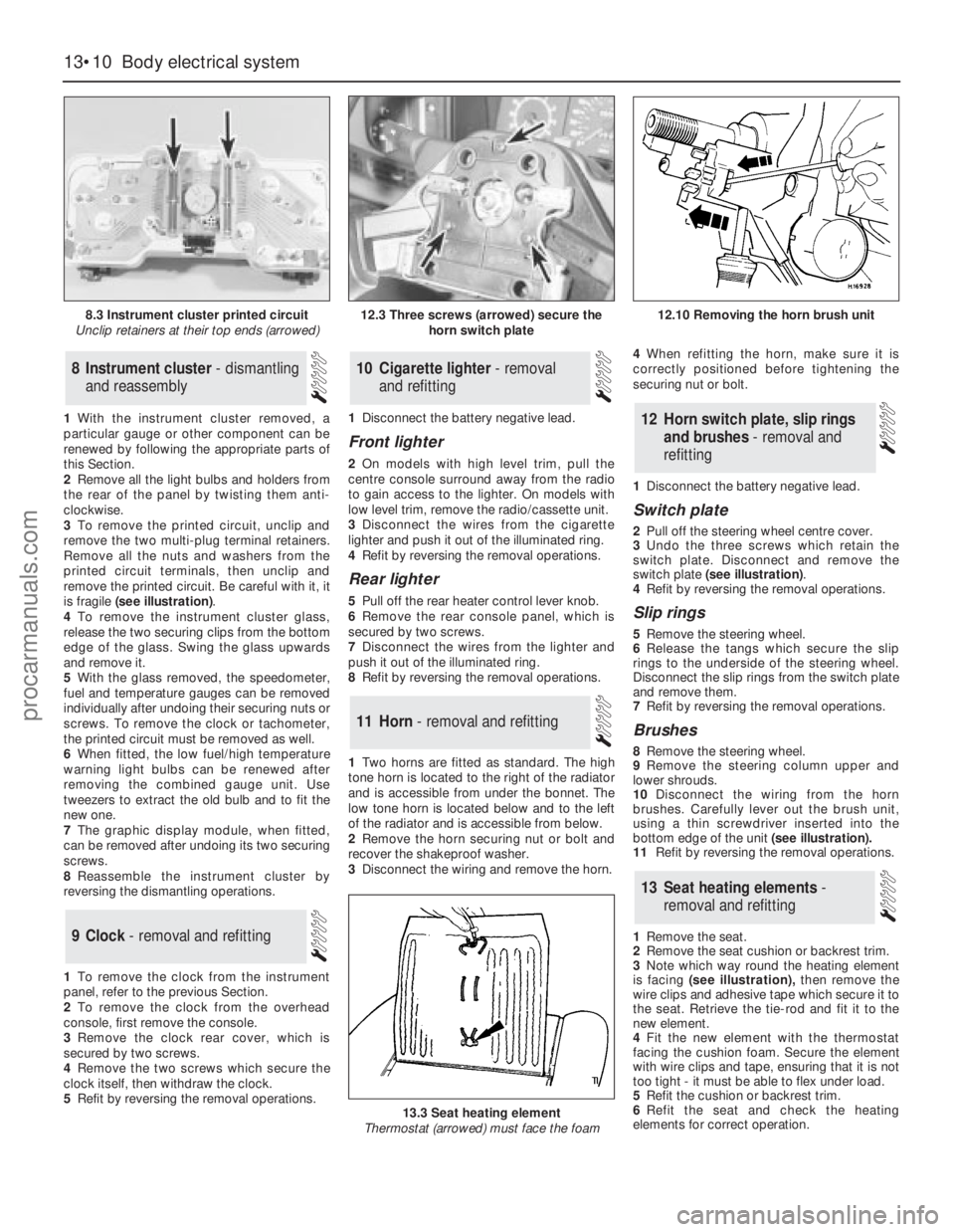
is fragile (see illustration).
4To remove the instrument cluster glass,
release the two securing clips from thebottom
edge of the glass. Swing the glass upwards
and remove it.
5With the glass removed, the speedometer,
fuel and temperature gauges can be removed
individually after undoing their securing nuts or
screws. To remove the clock or tachometer,
the printed circuit must be removed as well.
6When fitted, the low fuel/high temperature
warning light bulbs can be renewed after
removing the combined gauge unit. Use
tweezers to extract the old bulb and to fit the
new one.
7The graphic display module, when fitted,
can be removed after undoing its two securing
screws.
8Reassemble the instrument cluster by
reversing the dismantling operations.
1To remove the clock from the instrument
panel, refer to the previous Section.
2To remove the clock from the overhead
console, first remove the console.
3Remove the clock rear cover, which is
secured by two screws.
4Remove the two screws which secure the
clock itself, then withdraw the clock.
5Refit by reversing the removal operations.1Disconnect the battery negative lead.
Front lighter
2On models with high level trim, pull the
centre console surround away from the radio
to gain access to the lighter. On models with
low level trim, remove the radio/cassette unit.
3Disconnect the wires from the cigarette
lighter and push it out of the illuminated ring.
4Refit by reversing the removal operations.
Rear lighter
5Pull off the rear heater control lever knob.
6Remove the rear console panel, which is
secured by two screws.
7Disconnect the wires from the lighter and
push it out of the illuminated ring.
8Refit by reversing the removal operations.
1Two horns are fitted as standard. The high
tone horn is located to the right of the radiator
and is accessible from under the bonnet. The
low tone horn is located below and to the left
of the radiator and is accessible from below.
2Remove the horn securing nut or bolt and
recover the shakeproof washer.
3Disconnect the wiring and remove the horn.4When refitting the horn, make sure it is
correctly positioned before tightening the
securing nut or bolt.
1Disconnect the battery negative lead.
Switch plate
2Pull off the steering wheel centre cover.
3Undo the three screws which retain the
switch plate. Disconnect and remove the
switch plate (see illustration).
4Refit by reversing the removal operations.
Slip rings
5Remove the steering wheel.
6Release the tangs which secure the slip
rings to the underside of the steering wheel.
Disconnect the slip rings from the switch plate
and remove them.
7Refit by reversing the removal operations.
Brushes
8Remove the steering wheel.
9Remove the steering column upper and
lower shrouds.
10Disconnect the wiring from the horn
brushes. Carefully lever out the brush unit,
using a thin screwdriver inserted into the
bottom edge of the unit(see illustration).
11Refit by reversing the removal operations.
1Remove the seat.
2Remove the seat cushion or backrest trim.
3Note which way round the heating element
is facing (see illustration),then remove the
wire clips and adhesive tape which secure it to
the seat. Retrieve the tie-rod and fit it to the
new element.
4Fit the new element with the thermostat
facing the cushion foam. Secure the element
with wire clips and tape, ensuring that it is not
too tight - it must be able to flex under load.
5Refit the cushion or backrest trim.
6Refit the seat and check the heating
elements for correct operation.
13Seat heating elements -
removal and refitting
12Horn switch plate, slip rings
and brushes - removal and
refitting
11Horn - removal and refitting
10Cigarette lighter - removal
and refitting
9Clock - removal and refitting
8Instrument cluster - dismantling
and reassembly
13•10Body electrical system
8.3 Instrument cluster printed circuit
Unclip retainers at their top ends (arrowed)
13.3 Seat heating element
Thermostat (arrowed) must face the foam
12.3 Three screws (arrowed) secure the
horn switch plate12.10 Removing the horn brush unit
procarmanuals.com
Page 191 of 255
13•14Body electrical system
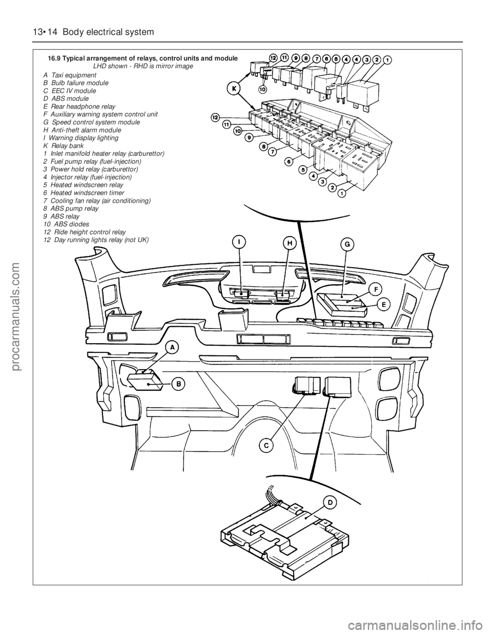
16.9 Typical arrangement of relays, control units and module
LHD shown - RHD is mirror image
A Taxi equipment
B Bulb failure module
C EEC IV module
D ABS module
E Rear headphone relay
F Auxiliary warning system control unit
G Speed control system module
H Anti-theft alarm module
I Warning display lighting
K Relay bank
1 Inlet manifold heater relay (carburettor)
2 Fuel pump relay (fuel-injection)
3 Power hold relay (carburettor)
4 Injector relay (fuel-injection)
5 Heated windscreen relay
6 Heated windscreen timer
7 Cooling fan relay (air conditioning)
8 ABS pump relay
9 ABS relay
10 ABS diodes
12 Ride height control relay
12 Day running lights relay (not UK)
procarmanuals.com
Page 195 of 255
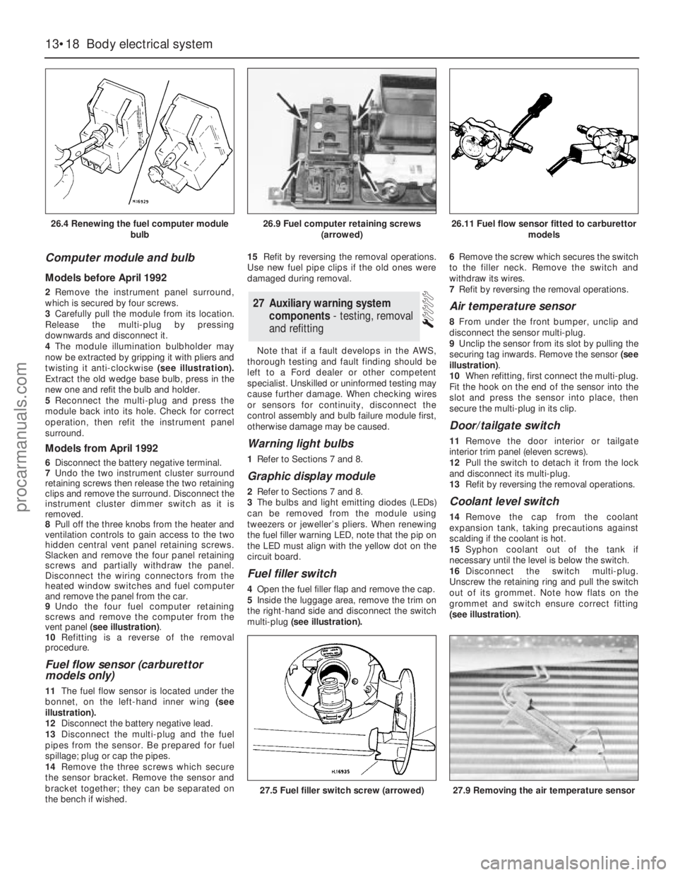
Computer module and bulb
Models before April 1992
2Remove the instrument panel surround,
which is secured by four screws.
3Carefully pull the module from its location.
Release the multi-plug by pressing
downwards and disconnect it.
4The module illumination bulbholder may
now be extracted by gripping it with pliers and
twisting it anti-clockwise (see illustration).
Extract the old wedge base bulb, press in the
new one and refit the bulb and holder.
5Reconnect the multi-plug and press the
module back into its hole. Check for correct
operation, then refit the instrument panel
surround.
Models from April 1992
6Disconnect the battery negative terminal.
7Undo the two instrument cluster surround
retaining screws then release the two retaining
clips and remove the surround. Disconnect the
instrument cluster dimmer switch as it is
removed.
8Pull off the three knobs from the heater and
ventilation controls to gain access to the two
hidden central vent panel retaining screws.
Slacken and remove the four panel retaining
screws and partially withdraw the panel.
Disconnect the wiring connectors from the
heated window switches and fuel computer
and remove the panel from the car.
9Undo the four fuel computer retaining
screws and remove the computer from the
vent panel (see illustration).
10Refitting is a reverse of the removal
procedure.
Fuel flow sensor (carburettor
models only)
11The fuel flow sensor is located under the
bonnet, on the left-hand inner wing (see
illustration).
12Disconnect the battery negative lead.
13Disconnect the multi-plug and the fuel
pipes from the sensor. Be prepared for fuel
spillage; plug or cap the pipes.
14Remove the three screws which secure
the sensor bracket. Remove the sensor and
bracket together; they can be separated on
the bench if wished.15Refit by reversing the removal operations.
Use new fuel pipe clips if the old ones were
damaged during removal.
Note that if a fault develops in the AWS,
thorough testing and fault finding should be
left to a Ford dealer or other competent
specialist. Unskilled or uninformed testing may
cause further damage. When checking wires
or sensors for continuity, disconnect the
control assembly and bulb failure module first,
otherwise damage may be caused.
Warning light bulbs
1Refer to Sections 7 and 8.
Graphic display module
2Refer to Sections 7 and 8.
3The bulbs and light emitting diodes (LEDs)
can be removed from the module using
tweezers or jeweller’s pliers. When renewing
the fuel filler warning LED, note that the pip on
the LED must align with the yellow dot on the
circuit board.
Fuel filler switch
4Open the fuel filler flap and remove the cap.
5Inside the luggage area, remove the trim on
the right-hand side and disconnect the switch
multi-plug(see illustration).6Remove the screw which secures the switch
to the filler neck. Remove the switch and
withdraw its wires.
7Refit by reversing the removal operations.
Air temperature sensor
8From under the front bumper, unclip and
disconnect the sensor multi-plug.
9Unclip the sensor from its slot by pulling the
securing tag inwards. Remove the sensor (see
illustration).
10When refitting, first connect the multi-plug.
Fit the hook on the end of the sensor into the
slot and press the sensor into place, then
secure the multi-plug in its clip.
Door/tailgate switch
11Remove the door interior ortailgate
interior trim panel (eleven screws).
12Pull the switch to detach it from the lock
and disconnect its multi-plug.
13Refit by reversing the removal operations.
Coolant level switch
14Remove the cap from the coolant
expansion tank, taking precautions against
scalding if the coolant is hot.
15Syphon coolant out of the tank if
necessary until the level is below the switch.
16Disconnect the switch multi-plug.
Unscrew the retaining ring and pull the switch
out of its grommet. Note how flats on the
grommet and switch ensure correct fitting
(see illustration).
27Auxiliary warning system
components - testing, removal
and refitting
13•18Body electrical system
26.4 Renewing the fuel computer module
bulb
27.5 Fuel filler switch screw (arrowed)27.9 Removing the air temperature sensor
26.9 Fuel computer retaining screws
(arrowed)26.11 Fuel flow sensor fitted to carburettor
models
procarmanuals.com
Page 249 of 255
REF•14Glossary of Technical Terms
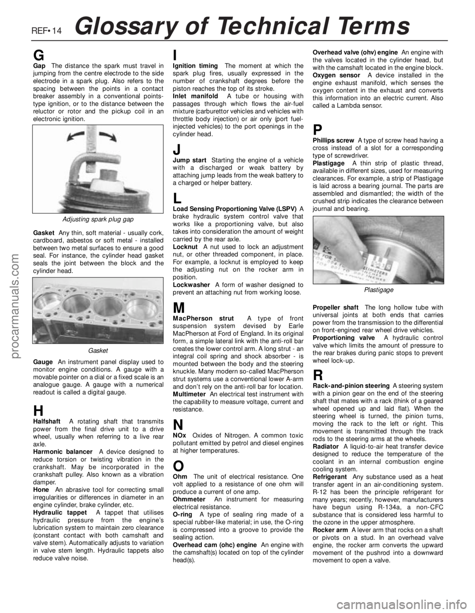
GGapThe distance the spark must travel in
jumping from the centre electrode to the side
electrode in a spark plug. Also refers to the
spacing between the points in a contact
breaker assembly in a conventional points-
type ignition, or to the distance between the
reluctor or rotor and the pickup coil in an
electronic ignition.
GasketAny thin, soft material - usually cork,
cardboard, asbestos or soft metal - installed
between two metal surfaces to ensure a good
seal. For instance, the cylinder head gasket
seals the joint between the block and the
cylinder head.
GaugeAn instrument panel display used to
monitor engine conditions. A gauge with a
movable pointer on a dial or a fixed scale is an
analogue gauge. A gauge with a numerical
readout is called a digital gauge.
HHalfshaftA rotating shaft that transmits
power from the final drive unit to a drive
wheel, usually when referring to a live rear
axle.
Harmonic balancerA device designed to
reduce torsion or twisting vibration in the
crankshaft. May be incorporated in the
crankshaft pulley. Also known as a vibration
damper.
HoneAn abrasive tool for correcting small
irregularities or differences in diameter in an
engine cylinder, brake cylinder, etc.
Hydraulic tappetA tappet that utilises
hydraulic pressure from the engine’s
lubrication system to maintain zero clearance
(constant contact with both camshaft and
valve stem). Automatically adjusts to variation
in valve stem length. Hydraulic tappets also
reduce valve noise.
IIgnition timingThe moment at which the
spark plug fires, usually expressed in the
number of crankshaft degrees before the
piston reaches the top of its stroke.
Inlet manifoldA tube or housing with
passages through which flows the air-fuel
mixture (carburettor vehicles and vehicles with
throttle body injection) or air only (port fuel-
injected vehicles) to the port openings in the
cylinder head.
JJump startStarting the engine of a vehicle
with a discharged or weak battery by
attaching jump leads from the weak battery to
a charged or helper battery.
LLoad Sensing Proportioning Valve (LSPV)A
brake hydraulic system control valve that
works like a proportioning valve, but also
takes into consideration the amount of weight
carried by the rear axle.
LocknutA nut used to lock an adjustment
nut, or other threaded component, in place.
For example, a locknut is employed to keep
the adjusting nut on the rocker arm in
position.
LockwasherA form of washer designed to
prevent an attaching nut from working loose.
MMacPherson strutA type of front
suspension system devised by Earle
MacPherson at Ford of England. In its original
form, a simple lateral link with the anti-roll bar
creates the lower control arm. A long strut - an
integral coil spring and shock absorber - is
mounted between the body and the steering
knuckle. Many modern so-called MacPherson
strut systems use a conventional lower A-arm
and don’t rely on the anti-roll bar for location.
MultimeterAn electrical test instrument with
the capability to measure voltage, current and
resistance.
NNOxOxides of Nitrogen. A common toxic
pollutant emitted by petrol and diesel engines
at higher temperatures.
OOhmThe unit of electrical resistance. One
volt applied to a resistance of one ohm will
produce a current of one amp.
OhmmeterAn instrument for measuring
electrical resistance.
O-ringA type of sealing ring made of a
special rubber-like material; in use, the O-ring
is compressed into a groove to provide the
sealing action.
Overhead cam (ohc) engineAn engine with
the camshaft(s) located on top of the cylinder
head(s).Overhead valve (ohv) engineAn engine with
the valves located in the cylinder head, but
with the camshaft located in the engine block.
Oxygen sensorA device installed in the
engine exhaust manifold, which senses the
oxygen content in the exhaust and converts
this information into an electric current. Also
called a Lambda sensor.
PPhillips screwA type of screw head having a
cross instead of a slot for a corresponding
type of screwdriver.
PlastigageA thin strip of plastic thread,
available in different sizes, used for measuring
clearances. For example, a strip of Plastigage
is laid across a bearing journal. The parts are
assembled and dismantled; the width of the
crushed strip indicates the clearance between
journal and bearing.
Propeller shaftThe long hollow tube with
universal joints at both ends that carries
power from the transmission to the differential
on front-engined rear wheel drive vehicles.
Proportioning valveA hydraulic control
valve which limits the amount of pressure to
the rear brakes during panic stops to prevent
wheel lock-up.
RRack-and-pinion steeringA steering system
with a pinion gear on the end of the steering
shaft that mates with a rack (think of a geared
wheel opened up and laid flat). When the
steering wheel is turned, the pinion turns,
moving the rack to the left or right. This
movement is transmitted through the track
rods to the steering arms at the wheels.
RadiatorA liquid-to-air heat transfer device
designed to reduce the temperature of the
coolant in an internal combustion engine
cooling system.
RefrigerantAny substance used as a heat
transfer agent in an air-conditioning system.
R-12 has been the principle refrigerant for
many years; recently, however, manufacturers
have begun using R-134a, a non-CFC
substance that is considered less harmful to
the ozone in the upper atmosphere.
Rocker armA lever arm that rocks on a shaft
or pivots on a stud. In an overhead valve
engine, the rocker arm converts the upward
movement of the pushrod into a downward
movement to open a valve.
Adjusting spark plug gap
Plastigage
Gasket
procarmanuals.com
Page 253 of 255
IND•2
F
Facia panels and trim - 12•12
Fast idle speed adjustment - 4•13
Fault finding- REF•5et seq
Fault-finding - electrical system - 5•3, 13•3
Final drive and driveshafts- 1•15, 9•1et
seq, 11•10, REF•9
Fire - 0•5
Flasher switch and unit - 13•11
Fluid leakage - REF•8
Fluid level checks - 1•6
Flywheel ring gear - 2A•14, 2C•15
Flywheel/driveplate - 2A•9, 2A•16, 2B•15,
2C•11, 2C•17
Foglight - 13•5,13•13
Footbrake - 0•11, 0•12
Footwell lights - 13•8
Fuel and exhaust systems- 0•14, 4•1et seq,
REF•8
Fuel computer components - 13•17
Fuel consumption high - REF•8
Fuel filler lock barrel - 12•7
Fuel filler switch - 13•18
Fuel filter - 1•19, 4•14
Fuel flow sensor - 13•18
Fuel gauge gives false reading - REF•11
Fuel odour - REF•8
Fuel pressure regulator - 4•18
Fuel temperature sensor - 5•12
Fuel trap (carburettor models) - 5•9
Fume or gas intoxication - 0•5
Fumes from exhaust system - REF•8
Fuses - 13•13
G
G (gravity) switch - 10•14
Gaskets - REF•4
Gear linkage - 7A•4
Gear selection problems - REF•8, REF•9
Glossary of technical terms - REF•12
Glovebox light - 13•8
Graphic display module - 13•18
Graphic equaliser - 13•21
Grille - 12•9
H
Handbrake “ON” switch - 13•12
Handbrake - 0•11, 10•11
Handles - 12•6
Hazard warning switch - 13•9, 13•13
HC emissions - 0•14
Headlight - 13•4, 13•6, 13•7, 13•11
Headlining - 12•11
Headphone relay - 13•22
Heated rear window switch - 13•13
Heated seat control switches - 13•13
Heater assembly - 3•7, 3•8, 3•9, 3•10,
13•11, 13•20
High frequency units - 13•22
High pressure hose - 10•10
Hinges - 1•12
Horn - 13•10
Horn emits intermittent or unsatisfactory
sound - REF•11Horn fails to operate - REF•11
Horn inoperative, or unsatisfactory in
operation - REF•11
Horn operates all the time - REF•11
Horn switch plate, slip rings and brushes -
13•10
HT leads - 5•5
HT voltage - 5•3
Hub - 11•11
Hydraulic system seals and hoses - 1•19
Hydraulic unit - 10•8, 10•9, 10•10
Hydrofluoric acid - 0•5
I
Idle mixture - 1•10
Idle speed - 1•10, 4•7, 4•9, 4•11, 4•14, 5•11
Idle speed control valve - 4•15
Idle speed linkage - 1•15
Ignition coil - 5•9
Ignition module - 5•8
Ignition system - 1•17
Ignition timing - 5•7, 5•11
Ignition/no-charge warning light fails to
come on - REF•11
Ignition/no-charge warning light remains
illuminated with engine running - REF•11
Ignition/starter switch - 13•11
Inlet manifold - 1•14, 4•19
Instrument cluster - 13•9, 13•10
Instrument illumination dimmer switch - 13•11
Instrument panel lights - 13•8
Instrument readings inaccurate or erratic -
REF•11
Instruments and electrical equipment - 1•16
Intensive maintenance - 1•6
Interior lights - 13•7
Introduction to the Ford Granada - 0•4
J
Jacking - 0•6
Joint mating faces - REF•4
Joystick fader control - 13•22
Jump starting - 0•10
Jumps out of gear - REF•8
L
Latch locks but will not unlock, or unlocks
but will not lock - REF•11
Leaks - 0•8, 1•10
Lighter - 13•10
Lighting master switch - 13•11
Lights - 13•4, 13•6
Lights inoperative - REF•10
Locknuts, locktabs and washers - REF•4
Locks - 1•12, 12•6, 12•7
Loudspeakers - 13•21, 13•22
Low pressure hose - 10•10
Lower arm - 11•9, 11•12
Lubricant leaks - REF•8
Lubricants and fluids - 1•2
Luggage area light - 13•8
M
Main bearings - 2A•11, 2A•15, 2B•17,
2C•12, 2C•15
Maintenance - bodywork and underframe -
12•1
Maintenance - upholstery and carpets -
12•2
Manifold absolute pressure (MAP) sensor -
5•12
Manifold heater - 5•11
Manual gearbox- 1•11, 2B•6, 2B•7, 7A•1et
seq, REF•8
Manual steering - 11•3
Master cylinder - 10•12
Mirror - 0•11, 12•12, 13•11
Mixture adjustment potentiometer - 4•19
Mixture adjustments - 4•7, 4•9, 4•11, 4•14
Motifs and emblems - 12•10
Motor factors - 0•9
Mountings - 2A•11, 2B•8, 2C•12
N
Needle valve and float - 4•11
Number plate light - 13•5
O
Oil - 1•6, 1•9
Oil filler cap - 1•10
Oil filter - 1•9, 2A•11
Oil leakage from final drive - REF•9
Oil pressure warning light illuminated with
engine running - REF•7
Oil pressure warning switch - 13•12
Oil pump - 2A•10, 2A•12, 2A•16, 2B•16,
2B•17, 2C•11, 2C•14, 2C•17
Oil seals - 2A•10, 2B•15, 2C•12, 9•2, 9•3,
REF•4
On load voltage check - 5•5
Open-circuit - 13•3
Overcooling - REF•7
Overhead console - 12•17
Overheating - REF•7
P
Pads - 1•10, 10•4, 10•5
Parcel shelf - 12•19
Parking light - 13•4
Pedal Travel Sensor (PTS) - 10•14
Pedals - 6•2, 4•6, 10•8
Pierburg 2V carburettor - 4•7, 4•9
Pistons and connecting rods - 2A•11, 2A•13,
2A•15, 2B•17, 2C•12, 2C•14, 2C•16
Pitching and/or rolling around corners, or
during braking - REF•10
Plastic components - 12•3
Poisonous or irrirant substances - 0•5
Power steering - 1•16, 11•3, 11•4, 11•6
Power valve diaphragm - 4•12
Pre-ignition (pinking) or knocking during
acceleration or under load - REF•7
Printed circuit board - 13•20
Propeller shaft- 8•1et seq, REF•9
Pushrods - 2C•13
Index
procarmanuals.com