1985 FORD GRANADA oil dipstick
[x] Cancel search: oil dipstickPage 4 of 255
1•3
1
Maintenance Schedule
Engine oil
SOHC:
With filter . . . . . . . . . . . . . . . . . . . . . . . . . . . . . .3.75 litres (6.6 pints)
DOHC:
With filter . . . . . . . . . . . . . . . . . . . . . . . . . . . . . . .4.5 litres (7.9 pints)
Without filter . . . . . . . . . . . . . . . . . . . . . . . . . . . . .4.0 litres (7.0 pints)
V6:
With filter . . . . . . . . . . . . . . . . . . . . . . . . . . . . . .4.25 litres (7.5 pints)
Cooling system
OHC . . . . . . . . . . . . . . . . . . . . . . . . . . . . . . . . . . . .8.0 litres (14.1 pints)
V6 . . . . . . . . . . . . . . . . . . . . . . . . . . . . . . . . . . . .8.5 litres (15.0 pints)
Fuel tank
All models . . . . . . . . . . . . . . . . . . . . . . . . . . . . .70 litres (15.4 gallons)
Manual gearbox
All models . . . . . . . . . . . . . . . . . . . . . . . . . . . . . .1.25 litres (2.2 pints)
Automatic transmission
All models (from dry) . . . . . . . . . . . . . . . . . . . . . . .8.5 litres (15.0 pints)
Final drive
7 inch crownwheel . . . . . . . . . . . . . . . . . . . . . . . . . .0.9 litres (1.6 pints)
7.5 inch crownwheel . . . . . . . . . . . . . . . . . . . . . . . . .1.3 litres (2.3 pints)
Power steering
OHC . . . . . . . . . . . . . . . . . . . . . . . . . . . . . . . . . . . .0.65 litres (1.1 pints)
V6 . . . . . . . . . . . . . . . . . . . . . . . . . . . . . . . . . . . .0.75 litres (1.3 pints)
Capacities
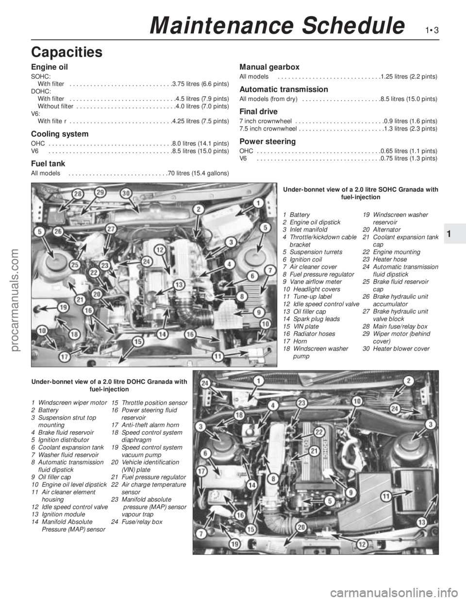
1 Battery
2 Engine oil dipstick
3 Inlet manifold
4 Throttle/kickdown cable
bracket
5 Suspension turrets
6 Ignition coil
7 Air cleaner cover
8 Fuel pressure regulator
9 Vane airflow meter
10 Headlight covers
11 Tune-up label
12 Idle speed control valve
13 Oil filler cap
14 Spark plug leads
15 VIN plate
16 Radiator hoses
17 Horn
18 Windscreen washer
pump19 Windscreen washer
reservoir
20 Alternator
21 Coolant expansion tank
cap
22 Engine mounting
23 Heater hose
24 Automatic transmission
fluid dipstick
25 Brake fluid reservoir
cap
26 Brake hydraulic unit
accumulator
27 Brake hydraulic unit
valve block
28 Main fuse/relay box
29 Wiper motor (behind
cover)
30 Heater blower cover
1 Windscreen wiper motor
2 Battery
3 Suspension strut top
mounting
4 Brake fluid reservoir
5 Ignition distributor
6 Coolant expansion tank
7 Washer fluid reservoir
8 Automatic transmission
fluid dipstick
9 Oil filler cap
10 Engine oil level dipstick
11 Air cleaner element
housing
12 Idle speed control valve
13 Ignition module
14 Manifold Absolute
Pressure (MAP) sensor15 Throttle position sensor
16 Power steering fluid
reservoir
17 Anti-theft alarm horn
18 Speed control system
diaphragm
19 Speed control system
vacuum pump
20 Vehicle identification
(VIN) plate
21 Fuel pressure regulator
22 Air charge temperature
sensor
23 Manifold absolute
pressure (MAP) sensor
vapour trap
24 Fuse/relay boxUnder-bonnet view of a 2.0 litre SOHC Granada with
fuel-injection
Under-bonnet view of a 2.0 litre DOHC Granada with
fuel-injection
procarmanuals.com
Page 5 of 255
1•4Maintenance Schedule
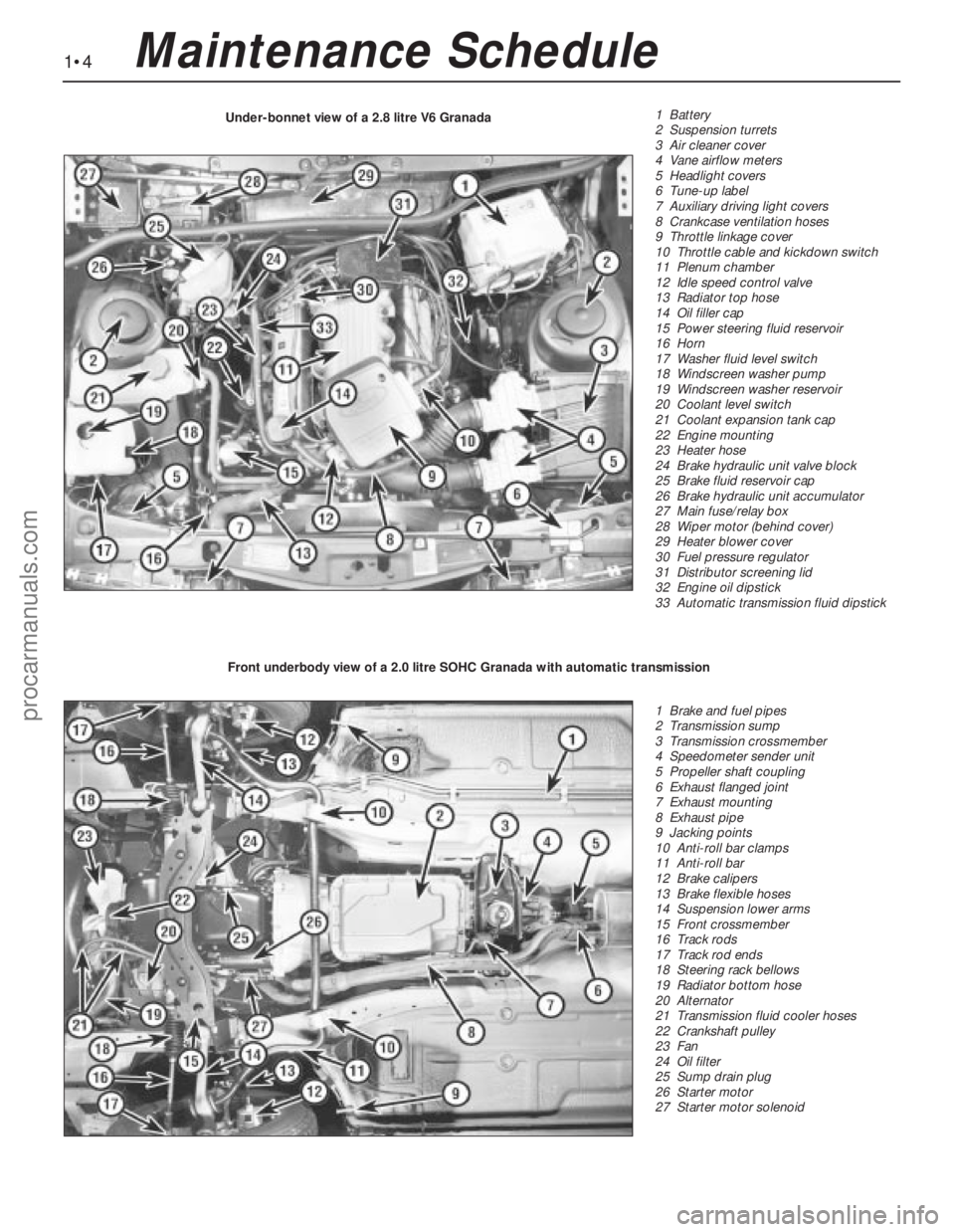
1 Battery
2 Suspension turrets
3 Air cleaner cover
4 Vane airflow meters
5 Headlight covers
6 Tune-up label
7 Auxiliary driving light covers
8 Crankcase ventilation hoses
9 Throttle linkage cover
10 Throttle cable and kickdown switch
11 Plenum chamber
12 Idle speed control valve
13 Radiator top hose
14 Oil filler cap
15 Power steering fluid reservoir
16 Horn
17 Washer fluid level switch
18 Windscreen washer pump
19 Windscreen washer reservoir
20 Coolant level switch
21 Coolant expansion tank cap
22 Engine mounting
23 Heater hose
24 Brake hydraulic unit valve block
25 Brake fluid reservoir cap
26 Brake hydraulic unit accumulator
27 Main fuse/relay box
28 Wiper motor (behind cover)
29 Heater blower cover
30 Fuel pressure regulator
31 Distributor screening lid
32 Engine oil dipstick
33 Automatic transmission fluid dipstick Under-bonnet view of a 2.8 litre V6 Granada
1 Brake and fuel pipes
2 Transmission sump
3 Transmission crossmember
4 Speedometer sender unit
5 Propeller shaft coupling
6 Exhaust flanged joint
7 Exhaust mounting
8 Exhaust pipe
9 Jacking points
10 Anti-roll bar clamps
11 Anti-roll bar
12 Brake calipers
13 Brake flexible hoses
14 Suspension lower arms
15 Front crossmember
16 Track rods
17 Track rod ends
18 Steering rack bellows
19 Radiator bottom hose
20 Alternator
21 Transmission fluid cooler hoses
22 Crankshaft pulley
23 Fan
24 Oil filter
25 Sump drain plug
26 Starter motor
27 Starter motor solenoid Front underbody view of a 2.0 litre SOHC Granada with automatic transmission
procarmanuals.com
Page 7 of 255
1•6Maintenance Procedures
This Chapter is designed to help the home
mechanic maintain his/her vehicle for safety,
economy, long life and peak performance.
The Chapter contains a master maintenance
schedule, followed by Sections dealing
specifically with each task in the schedule.
Visual checks, adjustments, component
renewal and other helpful items are included.
Refer to the accompanying illustrations of the
engine compartment and the underside of the
vehicle for the locations of the various
components.
Servicing your vehicle in accordance with
the mileage/time maintenance schedule and
the following Sections will provide a planned
maintenance programme, which should result
in a long and reliable service life. This is a
comprehensive plan, so maintaining some
items but not others at the specified service
intervals, will not produce the same results.
As you service your vehicle, you will
discover that many of the procedures can -
and should - be grouped together, because of
the particular procedure being performed, or
because of the close proximity of two
otherwise-unrelated components to one
another. For example, if the vehicle is raised
for any reason, the exhaust can be inspected
at the same time as the suspension and
steering components.
The first step in this maintenanceprogramme is to prepare yourself before the
actual work begins. Read through all the
Sections relevant to the work to be carried out,
then make a list and gather together all the
parts and tools required. If a problem is
encountered, seek advice from a parts
specialist, or a dealer service department.
If, from the time the vehicle is new, the
routine maintenance schedule is followed
closely, and frequent checks are made of fluid
levels and high-wear items, as suggested
throughout this manual, the engine will be kept
in relatively good running condition, and the
need for additional work will be minimised.
It is possible that there will be times when
the engine is running poorly due to the lack of
regular maintenance. This is even more likely if
a used vehicle, which has not received regular
and frequent maintenance checks, is
purchased. In such cases, additional work
may need to be carried out, outside of the
regular maintenance intervals.
If engine wear is suspected, a compression
test will provide valuable information regarding
the overall performance of the main internal
components. Such a test can be used as a
basis to decide on the extent of the work to be
carried out. If, for example, a compression test
indicates serious internal engine wear,
conventional maintenance as described in this
Chapter will not greatly improve theperformance of the engine, and may prove a
waste of time and money, unless extensive
overhaul work is carried out first.
The following series of operations are those
most often required to improve the
performance of a generally poor-running
engine:
Primary operations
a)Clean, inspect and test the battery
(Section 6)
b)Check all the engine-related fluids
(Section 3).
c)Check the condition and tension of the
auxiliary drivebelt (Section 21).
d)Renew the spark plugs (Section 20).
e)Inspect the distributor cap, rotor arm and
HT leads - as applicable (Chapter 5).
f)Check the condition of the air cleaner filter
element, and renew if necessary (Section 38).
g)Renew the fuel filter (Section 41).
h)Check the condition of all hoses, and
check for fluid leaks (Section 10).
i)Check the idle speed and mixture settings
- as applicable (Chapter 4).
If the above operations do not prove fully
effective, carry out the following secondary
operations:
Secondary operations
a)Check the charging system (Chapter 5).
b)Check the ignition system (Chapter 5).
c)Check the fuel system (Chapter 4).
d)Renew the distributor cap and rotor arm -
as applicable (Chapter 5).
f)Renew the ignition HT leads - as
applicable (Chapter 5).
2Intensive maintenance
1Introduction
Engine oil
1Check the oil level as follows.
2With the vehicle parked on level ground,
and with the engine having been stopped for a
few minutes, open and prop the bonnet.
Withdraw the dipstick, wipe it on a clean ragand re-insert it fully. Withdraw it again and
read the oil level relative to the marks on the
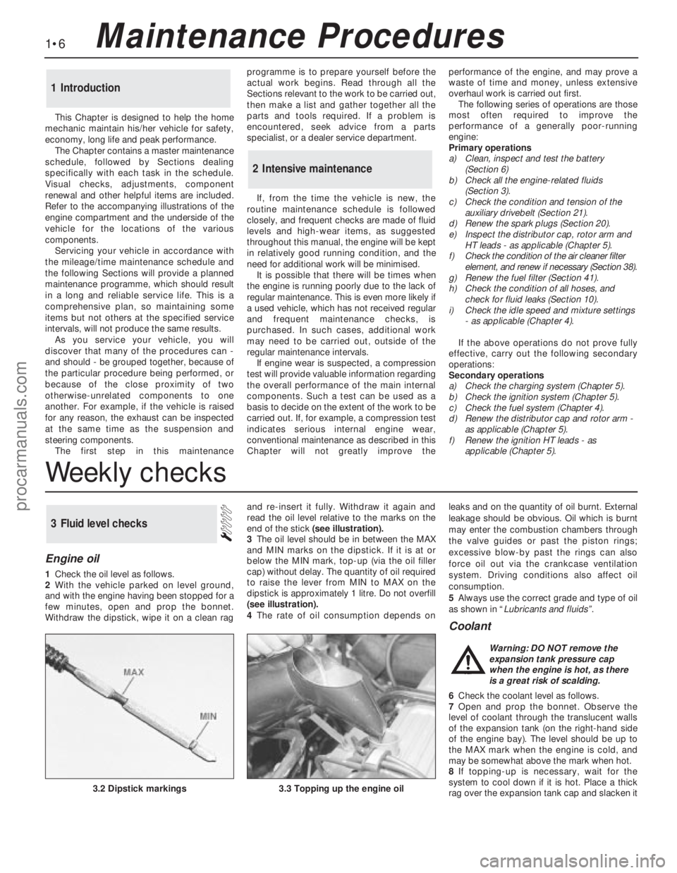
end of the stick (see illustration).
3The oil level should be in between the MAX
and MIN marks on the dipstick. If it is at or
below the MIN mark, top-up (via the oil filler
cap) without delay. The quantity of oil required
to raise the lever from MIN to MAX on the
dipstick is approximately 1 litre. Do not overfill
(see illustration).
4The rate of oil consumption depends onleaks and on the quantity of oil burnt. External
leakage should be obvious. Oil which is burnt
may enter the combustion chambers through
the valve guides or past the piston rings;
excessive blow-by past the rings can also
force oil out via the crankcase ventilation
system. Driving conditions also affect oil
consumption.
5Always use the correct grade and type of oil
as shown in “Lubricants and fluids”.
Coolant
6Check the coolant level as follows.
7Open and prop the bonnet. Observe the
level of coolant through the translucent walls
of the expansion tank (on the right-hand side
of the engine bay). The level should be up to
the MAX mark when the engine is cold, and
may be somewhat above the mark when hot.
8If topping-up is necessary, wait for the
system to cool down if it is hot. Place a thick
rag over the expansion tank cap and slacken it
3Fluid level checks
3.2 Dipstick markings3.3 Topping up the engine oil
Warning: DO NOT remove the
expansion tank pressure cap
when the engine is hot, as there
is a great risk of scalding.
Weekly checks
procarmanuals.com
Page 10 of 255
3Persistent need for topping-up the battery
electrolyte suggests either that the alternator
output is excessive. or that the battery is
approaching the end of its life.
4Further information on the battery, charging
and jump-starting can be found in Chapter 5,
and in the preliminary Sections of this manual.1Clean the wiper blades and the windscreen,
using a solution of concentrated washer fluid
or methylated spirit. Similarly clean the
headlight lens and wiper blades.
2Check the condition of the wiper blades; if
they are cracked or show any signs of
deterioration, or if the glass swept area is
smeared, renew them. At the same time,
check the headlight wiper blades (where fitted)
for condition, and renew if necessary.
3To remove a blade, hinge the arm and blade
away from the screen. Press the tab on the
spring clip in the middle of the blade and
unhook the blade from the arm. 4Refit the blade by sliding it onto the hook on
the arm(see illustration).
5Check that the windscreen washer jets
operate correctly, and direct the washer fluid
towards the upper area of the wiper blade
stroke. If necessary, use a pin to reposition the
washer jets.
7Wiper blade check
1Before starting this procedure, gather
together all the necessary tools and materials.
Also make sure that you have plenty of clean
rags and newspapers handy, to mop up any
spills. Ideally, the engine oil should be warm,
as it will drain better, and more built-up sludge
will be removed with it. Take care, however,
not to touch the exhaust or any other hot parts
of the engine when working under the vehicle.
To avoid any possibility of scalding, and toprotect yourself from possible skin irritants
and other harmful contaminants in used
engine oils, it is advisable to wear gloves when
carrying out this work.
2Access to the underside of the vehicle will be
greatly improved if it can be raised on a lift,
driven onto ramps, or jacked up and supported
on axle stands (see “Jacking”). Whichever
method is chosen, make sure that the vehicle
remains level, or if it is at an angle, that the drain
plug is at the lowest point.
3Slacken the drain plug about half a turn.
Position the draining container under the drain
plug, then remove the plug completely. If
possible, try to keep the plug pressed into the
sump while unscrewing it by hand the last
couple of turns. As the plug releases from the
threads, move it away sharply so the stream of
oil issuing from the sump runs into the
container, not up your sleeve. Recover the
sealing washer from the drain plug.
4Allow some time for the old oil to drain,
noting that it may be necessary to reposition
the container as the oil flow slows to a trickle.
5After all the oil has drained, wipe off the
drain plug with a clean rag. Check the sealing
washer for condition, and renew it if
necessary. Clean the area around the drain
plug opening, and refit the plug. Tighten the
plug to the specified torque.
6Move the container into position under the
oil filter. On SOHC engines, the filter is located
on the left-hand side of the cylinder block in
front of the engine bearer. On DOHC and V6
engines, the filter is located on the right-hand
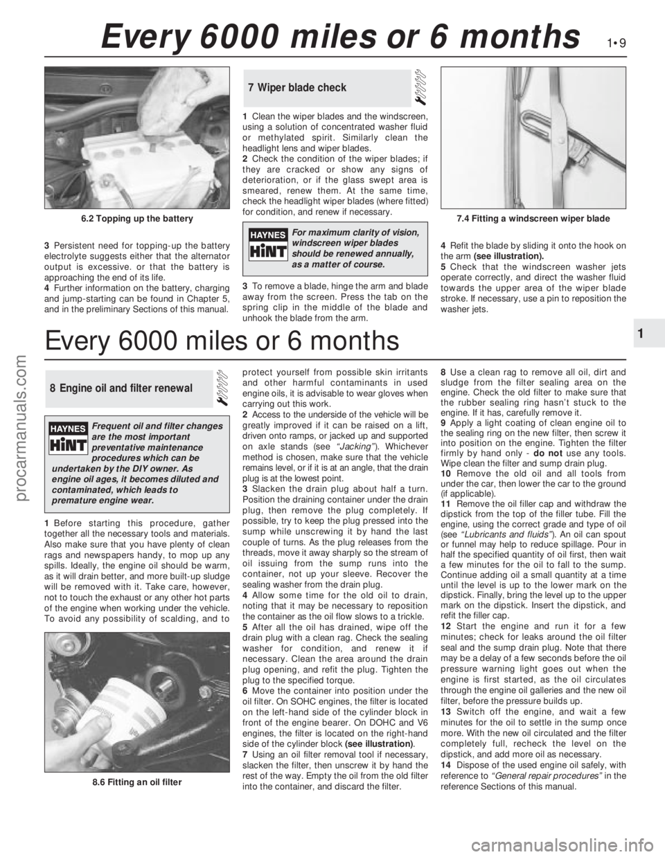
side of the cylinder block (see illustration).
7Using an oil filter removal tool if necessary,
slacken the filter, then unscrew it by hand the
rest of the way. Empty the oil from the old filter
into the container, and discard the filter.8Use a clean rag to remove all oil, dirt and
sludge from the filter sealing area on the
engine. Check the old filter to make sure that
the rubber sealing ring hasn’t stuck to the
engine. If it has, carefully remove it.
9Apply a light coating of clean engine oil to
the sealing ring on the new filter, then screw it
into position on the engine. Tighten the filter
firmly by hand only - do notuse any tools.
Wipe clean the filter and sump drain plug.
10Remove the old oil and all tools from
under the car, then lower the car to the ground
(if applicable).
11Remove the oil filler cap and withdraw the
dipstick from the top of the filler tube. Fill the
engine, using the correct grade and type of oil
(see “Lubricants and fluids”). An oil can spout
or funnel may help to reduce spillage. Pour in
half the specified quantity of oil first, then wait
a few minutes for the oil to fall to the sump.
Continue adding oil a small quantity at a time
until the level is up to the lower mark on the
dipstick. Finally, bring the level up to the upper
mark on the dipstick. Insert the dipstick, and
refit the filler cap.
12Start the engine and run it for a few
minutes; check for leaks around the oil filter
seal and the sump drain plug. Note that there
may be a delay of a few seconds before the oil
pressure warning light goes out when the
engine is first started, as the oil circulates
through the engine oil galleries and the new oil
filter, before the pressure builds up.
13Switch off the engine, and wait a few
minutes for the oil to settle in the sump once
more. With the new oil circulated and the filter
completely full, recheck the level on the
dipstick, and add more oil as necessary.
14Dispose of the used engine oil safely, with
reference to “General repair procedures”in the
reference Sections of this manual.
8Engine oil and filter renewal
1•9
1
Every 6000 miles or 6 months
8.6 Fitting an oil filter
6.2 Topping up the battery7.4 Fitting a windscreen wiper blade
Every 6000 miles or 6 months
For maximum clarity of vision,
windscreen wiper blades
should be renewed annually,
as a matter of course.
Frequent oil and filter changes
are the most important
preventative maintenance
procedures which can be
undertaken by the DIY owner. As
engine oil ages, it becomes diluted and
contaminated, which leads to
premature engine wear.
procarmanuals.com
Page 12 of 255
engine valve clearances must be correct. The
ignition system must also be in good
condition.
3Mixture adjustment is not usual on a routine
basis. If the CO level is incorrect, proceed as
follows.
4Connect the exhaust gas analyser as
instructed by the manufacturers.
5Raise the engine speed to 3000 rpm
approximately and hold it at this speed for
30 seconds, then allow it to idle. Repeat this
procedure every 60 seconds until adjustment
is complete.6Read the CO level when it has stabilised
after the 3000 rpm burst. The desired level is
given in the Specifications of Chapter 4
(Pierburg 2V carburettor).
7If the idle mixture needs adjustment, turn
the mixture adjusting screw. The screw may
be covered by a tamperproof plug.
8Recheck the idle speed after adjusting the
mixture.
9Stop the engine and disconnect the test
gear. 10Fit a new tamperproof plug to the mixture
adjusting screw if required.
2.0 litre SOHC engine
11If mixture adjustment is required, proceed
as described for the 1.8 litre engine above.
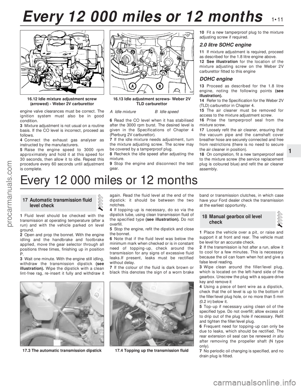
12See illustrationfor the location of the
mixture adjusting screw on the Weber 2V
carburettor fitted to this engine
DOHC engine
13Proceed as described for the 1.8 litre
engine, noting the following points (see
illustration).
14Refer to the Specification for the Weber 2V
(TLD) carburettor in Chapter 4.
15The air cleaner must be removed for
access to the mixture adjustment screw.
16Prise the tamperproof seal from the
mixture screw.
17Loosely refit the air cleaner, ensuring that
the vacuum pipe and the camshaft cover
breather hose are securely connected and free
from restrictions (there is no need to secure
the air cleaner in position).
18On completion, fit a new tamperproof seal
to the mixture screw (the service replacement
plug is coloured blue) and refit the air cleaner
assembly.
1Fluid level should be checked with the
transmission at operating temperature (after a
run) and with the vehicle parked on level
ground.
2Open and prop the bonnet. With the engine
idling and the handbrake and footbrake
applied, move the gear selector through all
positions three times, finishing up in position
P.
3Wait one minute. With the engine still idling,
withdraw the transmission dipstick (see
illustration).Wipe the dipstick with a clean
lint-free rag, re-insert it fully and withdraw itagain. Read the fluid level at the end of the
dipstick: it should be between the two
notches.
4If topping-up is necessary, do so via the
dipstick tube, using clean transmission fluid of
the specified type (see illustration).Do not
overfill.
5Stop the engine, refit the dipstick and close
the bonnet.
6Note that if the fluid level was below the
minimum mark when checked or is in constant
need oftopping-up, check around the
transmission for any signs of excessive fluid
leaks.If present, leaks must be rectified
without delay.
7If the colour of the fluid is dark brown or
black this denotes the sign of a worn brakeband or transmission clutches, in which case
have your Ford dealer check the transmission
at the earliest opportunity.
1Place the vehicle over a pit, or raise and
support it at front and rear. The vehicle must
be level for an accurate check.
2If the transmission is hot after a run, allow it
to cool for a few minutes. This is necessary
because the oil can foam when hot and give a
false level reading.
3Wipe clean around the filler/level plug,
which is located on the left-hand side of the
gearbox. Unscrew the plug with a square drive
key and remove it
4Using a piece of bent wire as a dipstick,
check that the oil level is up to the bottom of
the filler/level plug hole, or no more than 5 mm
(0.2 in) below it.
5Top-up if necessary using clean oil of the
specified type. Do not overfill; allow excess oil
to drip out of the plug hole if necessary. Refit
and tighten the filler/level plug.
6Frequent need for topping-up can only be
due to leaks, which should be rectified. The
rear extension oil seal can be renewedin situ
after removing the propeller shaft (N type
only).
7No periodic oil changing is specified, and no
drain plug is fitted.
18Manual gearbox oil level
check
17Automatic transmission fluid
level check
1•11
1
Every 12 000 miles or 12 months
16.13 Idle adjustment screws- Weber 2V
TLD carburettor
A Idle mixtureB Idle speed
16.12 Idle mixture adjustment screw
(arrowed) - Weber 2V carburettor
17.4 Topping up the transmission fluid17.3 The automatic transmission dipstick
Every 12 000 miles or 12 months
procarmanuals.com
Page 16 of 255
1Remove the radiator grille being careful not
to damage the condenser fins.
2Check the refrigerant charge as follows. The
engine should be cold and the ambient
temperature should be between 18°and 25°C
(64°and 77°F).
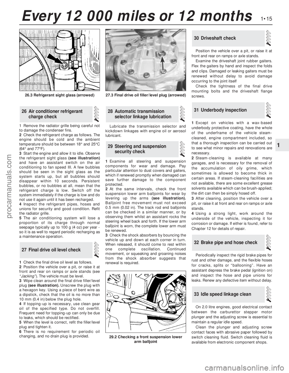
3Start the engine and allow it to idle. Observe
the refrigerant sight glass(see illustration)
and have an assistant switch on the air
conditioning to fan speed III. A few bubbles
should be seen in the sight glass as the
system starts up, but all bubbles should
disappear within 10 seconds. Persistent
bubbles, or no bubbles at all, mean that the
refrigerant charge is low. Switch off the
system immediately if the charge is low and do
not use it again until it has been recharged.
4Inspect the refrigerant pipes, hoses and
unions for security and good condition. Refit
the radiator grille.
5The air conditioning system will lose a
proportion of its charge through normal
seepage typically up to 100 g (4 oz) per year -
so it is as well to regard periodic recharging as
a maintenance operation.
1Check the final drive oil level as follows.
2Position the vehicle over a pit, or raise it at
front and rear on ramps or axle stands (see
“Jacking”). The vehicle must be level.
3Wipe clean around the final drive filler/level
plug (see illustration).Unscrew the plug with
a hexagon key. Using a piece of bent wire as
a dipstick, check that the oil is no more than
10 mm (0.4 in) below the plug hole.
4If topping-up is necessary, use clean gear
oil of the specified type. Do not overfill.
Frequent need for topping-up can only be due
to leaks, which should be rectified.
5When the level is correct, refit the filler/level
plug and tighten it.
6There is no requirement for periodic oil
changing, and no drain plug is provided. Lubricate the transmission selector and
kickdown linkages with engine oil or aerosol
lubricant.
1Examine all steering and suspension
components for wear and damage. Pay
particular attention to dust covers and gaiters,
which if renewed promptly when damaged can
save further damage to the component
protected.
2At the same intervals, check the front
suspension lower arm balljoints for wear by
levering up the arms(see illustration).
Balljoint free movement must not exceed
0.5 mm (0.02 in). The track rod end balljoints
can be checked in a similar manner, or by
observing them whilst an assistant rocks the
steering wheel back and forth. If the lower arm
balljoint is worn, the complete lower arm must
be renewed.
3Check the shock absorbers by bouncing the
vehicle up and down at each corner in turn.
When released, it should come to rest within
one complete oscillation. Continued
movement, or squeaking and groaning noises
from the shock absorber suggests that
renewal is required.Position the vehicle over a pit, or raise it at
front and rear on ramps or axle stands.
Examine the driveshaft joint rubber gaiters.
Flex the gaiters by hand and inspect the folds
and clips. Damaged or leaking gaiters must be
renewed without delay to avoid damage
occurring to the joint itself
Check the tightness of the final drive
mounting bolts and the driveshaft flange
screws.
1Except on vehicles with a wax-based
underbody protective coating, have the whole
of the underframe of the vehicle steam-
cleaned, engine compartment included, so
that a thorough inspection can be carried out
to see what minor repairs and renovations are
necessary.
2Steam-cleaning is available at many
garages, and is necessary for the removal of
the accumulation of oily grime, which
sometimes is allowed to become thick in
certain areas. If steam-cleaning facilities are
not available, there are some excellent grease
solvents available which can be brush-applied;
the dirt can then be simply hosed off.
3After cleaning, position the vehicle over a
pit, or raise it at front and rear on ramps or axle
stands.
4Using a strong light, work around the
underside of the vehicle, inspecting it for
corrosion or damage. If either is found, refer to
Chapter 12 for details of repair.
Periodically inspect the rigid brake pipes for
rust and other damage, and the flexible hoses
for cracks, splits or “ballooning”. Have an
assistant depress the brake pedal (ignition on)
and inspect the hose and pipe unions for
leaks. Renew any defective item without delay.
On 2.0 litre engines, good electrical contact
between the carburettor stepper motor
plunger and the adjusting screw is essential to
maintain a regular idle speed.
Clean the plunger and adjusting screw
contact faces with abrasive paper followed by
switch cleaning fluid. Switch cleaning fluid is
available from electronic component shops.
33Idle speed linkage clean
32Brake pipe and hose check
31Underbody inspection
30Driveshaft check
29Steering and suspension
security check
28Automatic transmission
selector linkage lubrication
27Final drive oil level check
26Air conditioner refrigerant
charge check
1•15
1
Every 12 000 miles or 12 months
27.3 Final drive oil filler/level plug (arrowed)
29.2 Checking a front suspension lower
arm balljoint
26.3 Refrigerant sight glass (arrowed)
procarmanuals.com
Page 29 of 255
14Take the weight of the engine and remove
the two engine bearer-to-mounting nuts.
15Lift the engine/transmission, at the same
time lowering the trolley jack. Draw the unit
forwards and lift it out of the engine bay.
16Temporarily refit the anti-roll bar if the
vehicle is to be moved.
1With the engine and gearbox on the bench,
remove the starter motor.
2Remove the bolt from the engine adapter plate.
3Remove the bracing strap and the
remaining engine-to-bellhousing bolts.
4With the aid of an assistant draw the
gearbox off the engine. Do not allow the weight
of the gearbox to hang on the input shaft.
1It is best to mount the engine on a
dismantling stand, but if this is not available,
stand the engine on a strong bench at a
comfortable working height. Failing this, it will
have to be stripped down on the floor.
2Cleanliness is most important, and if the
engine is dirty, it should be cleaned with
paraffin while keeping it in an upright position.
3Avoid working with the engine on a concrete
floor, as grit can be a real source of trouble.
4As parts are removed, clean them in paraffin.
However, do not immerse parts with internal
oilways in paraffin as it is difficult to remove,
usually requiring a high pressure hose.
5It is advisable to have suitable containers to
hold small items according to their use, as this
will help when reassembling the engine and
also prevent possible losses.
6Always obtain complete sets of gaskets
when the engine is being dismantled, but
retain the old gaskets with a view of using
them as a pattern to make a replacement if a
new one is not available.7When possible, refit nuts, bolts and washers
in their location after being removed, as this
helps protect the threads and will also be
helpful when reassembling the engine.
8Retain unserviceable components in order
to compare them with the new parts supplied.
9A Torx key, size T55, will be needed for
dealing with the cylinder head bolts. A 12-
spline key (to fit bolt size M8) will be needed
for the oil pump bolts. Other Torx and 12-
spline bolts may be encountered; sets of the
keys required to deal with them are available
from most motor accessory shops and tool
factors.
10Another tool which is useful, though by no
means essential, is a valve spring compressor
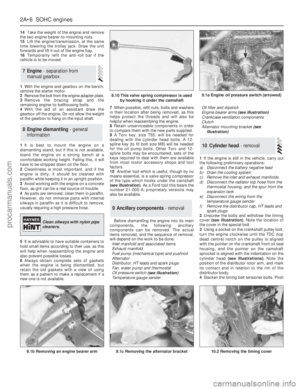
of the type which hooks under the camshaft
(see illustration). As a Ford tool this bears the
number 21-005-A; proprietary versions may
also be available.
Before dismantling the engine into its main
components, the following ancillary
components can be removed. The actual
items removed, and the sequence of removal,
will depend on the work to be done:
Inlet manifold and associated items
Exhaust manifold
Fuel pump (mechanical type) and pushrod
Alternator
Distributor, HT leads and spark plugs
Fan, water pump and thermostat
Oil pressure switch
(see illustration)
Temperature gauge senderOil filter and dipstick
Engine bearer arms (see illustration)
Crankcase ventilation components
Clutch
Alternator mounting bracket (see
illustration)
1If the engine is still in the vehicle, carry out
the following preliminary operations:
a)Disconnect the battery negative lead
b)Drain the cooling system
c)Remove the inlet and exhaust manifolds
d)Disconnect the radiator top hose from the
thermostat housing, and the spur from the
expansion tank
e)Disconnect the wiring from the
temperature gauge sender
f)Remove the distributor cap, HT leads and
spark plugs
2Unscrew the bolts and withdraw the timing
cover (see illustration). Note the location of
the cover in the special bolt.
3Using a socket on the crankshaft pulley bolt.
turn the engine clockwise until the TDC (top
dead centre) notch on the pulley is aligned
with the pointer on the crankshaft front oil seal
housing, and the pointer on the camshaft
sprocket is aligned with the indentation on the
cylinder head (see illustrations).Note the
position of the distributor rotor arm, and mark
its contact end in relation to the rim of the
distributor body.
4Slacken the timing belt tensioner bolts. Pivot
10Cylinder head - removal
9Ancillary components - removal
8Engine dismantling - general
information
7Engine - separation from
manual gearbox
2A•6SOHCengines
9.1a Engine oil pressure switch (arrowed)
9.1b Removing an engine bearer arm9.1c Removing the alternator bracket
8.10 This valve spring compressor is used
by hooking it under the camshaft
Clean oilways with nylon pipe
cleaners.
10.2 Removing the timing cover
procarmanuals.com
Page 50 of 255
21Working through the starter motor
aperture, unscrew the four torque converter-
to-driveplate nuts. It will be necessary to turn
the crankshaft using a spanner on the
crankshaft pulley bolt in order to gain access
to each nut in turn through the aperture.
22Where applicable, remove the bolt
securing the transmission fluid dipstick tube to
the left-hand side of the cylinder block.
23Unscrew the engine-to-transmission bolts,
noting the locations of the bolts, and the
positions of the earth strap and any wiring
clips attached to the bolts. Recover any shims
fitted between the sump and the transmission
when removing the lower engine-to-
transmission bolts.
24Unscrew the bolt from the engine adapter
plate and, where applicable, pull the blanking
plug from the adapter plate.
25Pull the engine and the transmission apart,
ensuring that the torque converter is held firmly
in place in the transmission housing, otherwise
it could fall out resulting in fluid spillage and
possible damage. It may be necessary to rock
the units slightly to separate them.
1Reverse the procedure described in
paragraphs 1 to 40 ofSection 5, noting the
following points.
2Before attempting to refit the engine, check
that the clutch friction disc is centralised.
3Check that the clutch release arm and
bearing are correctly fitted, and lightly grease
the input shaft splines.
4Check that the engine adapter plate is
correctly positioned on the locating dowels. If
necessary, a cable-tie can be used to
temporarily secure the adapter plate in
position on the cylinder block using one of the
engine-to-gearbox bolt holes.
5If shims were fitted between the sump and
the gearbox, refit them in their original
locations when mating the engine to the
gearbox. If the engine has been overhauled,
where applicable fit the relevant shims as
calculated during engine reassembly .
6Reconnect the clutch cable to the release arm,
ensuring that it is routed as noted during removal.
7Ensure that the roadwheels and the steering
wheel are in the straight-ahead position then
align the marks made on removal and reconnect
the intermediate shaft to the steering gearing.
Tighten the clamp bolt to the specified torque.
8Refit the exhaust downpipe.
9Fill the engine with the correct grade and
quantity of oil.
10Check the throttle cable adjustment. Where
necessary, also adjust the speed control cable
in the same way so that there is only a small
amount of slack present in the cable.
11Reconnect the coolant hoses to the water
pump housing.
12Fill the cooling system .
13Tighten all fixings to the specified torque,
where applicable.1Reverse the procedure described in Section 6,
noting the following points.
2Check that the engine adapter plate is
correctly positioned on the locating dowels. If
necessary, a cable-tie can be used to
temporarily secure the adapter plate in
position on the cylinder block using one of the
engine-to-transmission bolt holes.
3As the torque converter is only loosely
engaged in the transmission, care must be taken
to prevent the torque converter from falling out
forwards. When the torque converter hub is fully
engaged with the fluid pump drivegear in the
transmission, distance A (see illustration 2.20 in
Chapter 7B)must be as specified. Incorrect
installation of the torque converter will result in
damageto the transmission.
4If shims were fitted between the sump and
the transmission, refit them in their original
locations when mating the engine to the
transmission. If the engine has been
overhauled, where applicable fit the relevant
shims as calculated during engine reassembly.
5As the engine is installed, guide the torque
converter studs through the holes in the
driveplate. When the engine is positioned flush
with the engine adapter plate and the
transmission housing, check that the torque
converter is free to move axially a small
amount before refitting and tightening the
engine-to-transmission bolts.
6Do not tighten the torque converter-to-
driveplate nuts until the lower engine-to-
transmission bolts have been fitted and
tightened.
7Ensure that the roadwheels and the steering
wheel are in the straight-ahead position then
align the marks made on removal and
reconnect the intermediate shaft to the
steering gearing. Tighten the clamp bolt to the
specified torque.
8Refit the exhaust downpipe.
9Fill the engine with the correct grade and
quantity of oil.
10Check the throttle cable adjustment. Where
necessary, also adjust the speed control cable
in the same way so that there is only a small
amount of slack present in the cable.
11Reconnect the coolant hoses to the water
pump housing.
12Fill the cooling system.
13Tighten all fixings to the specified torque,
where applicable.
1Reverse the procedure described in Section 7,
noting the following points.
2Before attempting to reconnect the engine
to the gearbox, check that the clutch friction
disc is centralised.
3Check that the clutch release arm andbearing are correctly fitted, and lightly grease
the input shaft splines.
4Check that the engine adapter plate is
correctly positioned on the locating dowels. If
necessary, a cable-tie can be used to
temporarily secure the adapter plate in
position on the cylinder block using one of the
engine-to-gearbox bolt holes.
5If shims were fitted between the sump and
the gearbox, refit them in their original
locations when mating the engine to the
gearbox. If the engine has been overhauled,
where applicable fit the relevant shims as
calculated during engine reassembly.
6Ensure that the roadwheels and the steering
wheel are in the straight-ahead position then
align the marks made on removal and
reconnect the intermediate shaft to the
steering gearing. Tighten the clamp bolt to the
specified torque.
7Reconnect the clutch cable to the release
arm, ensuring that it is routed as noted during
removal.
8Refit the propeller shaft.
9Refit the exhaust system.
10Fill the engine with the correct grade and
quantity of oil.
11Check the throttle cable adjustment. Where
necessary, also adjust the speed control cable
in the same way so that there is only a small
amount of slack present in the cable.
12Reconnect the coolant hoses to the water
pump housing.
13Fill the cooling system.
14Check and if necessary top-up the
gearbox oil level.
15Tighten all fixings to the specified torque,
where applicable.
1Reverse the procedure described in Section 8,
noting the following points.
2Check that the engine adapter plate is
correctly positioned on the locating dowels. If
necessary, a cable-tie can be used to
temporarily secure the adapter plate in
position on the cylinder block using one of the
engine-to-transmission bolt holes.
3As the torque converter is only loosely
engaged in the transmission, care must be taken
to prevent the torque converter from falling out
forwards. When the torque converter hub is fully
engaged with the fluid pump drivegear in the
transmission, distance A (see illustration 2.20 in
Chapter 7B)must be as specified. Incorrect
installation of the torque converter will result in
damage to the transmission.
4If shims were fitted between the sump and
the transmission, refit them in their original
locations when mating the engine to the
transmission. If the engine has been
overhauled, where applicable fit the relevant
shims as calculated during engine reassembly.
5As the engine and transmission are mated
12Engine/automatic
transmission assembly -
reconnection and refitting
11Engine/manual gearbox
assembly - reconnection and
refitting
10Engine - refitting (automatic
transmission in vehicle)
9Engine - refitting (manual
gearbox in vehicle)
DOHCengine 2B•7
2B
procarmanuals.com