1985 FORD GRANADA clock
[x] Cancel search: clockPage 11 of 255
1Firmly apply the handbrake, then jack up the
front and rear of the car and support it
securely on axle stands (see “Jacking”).
2For a quick check, the front brake disc pads
can be inspected without removing the front
wheels, using a mirror and a torch through the
aperture in the rear face of the caliper. If any
one pad is worn down to the minimum
specified, all four pads (on both front wheels)
must be renewed.
3It is necessary to remove the rear wheels in
order to inspect the rear pads. The pads can
be viewed through the top of the caliper after
removing the spring clip. If any one pad is
worn down to the minimum specified, all four
pads (on both rear wheels) must be renewed.
4For a comprehensive check, the brake pads
should be removed and cleaned. The
operation of the caliper can then also be
checked, and the condition of the brake discs
can be fully examined on both sides. Refer to
Chapter 10 for further information.
5At the same interval, check the function of
the brake fluid level warning light. Chock the
wheels, release the handbrake and switch on
the ignition. Unscrew and raise the brake fluid
reservoir cap whilst an assistant observes the
warning light: it should come on as the level
sensor is withdrawn from the fluid. Refit the
cap.
6On completion, refit the wheels and lower
the car to the ground.
1Visually inspect the engine joint faces,
gaskets and seals for any signs of water or oil
leaks. Pay particular attention to the areas
around the rocker cover, cylinder head, oil
filter and sump joint faces. Bear in mind that
over a period of time some very slight seepage
from these areas is to be expected but what
you are really looking for is any indication of a
serious leak. Should a leak be found, renew
the offending gasket or oil seal by referring to
the appropriate Chapter(s) in this manual.
2Similarly, check the transmission for oil
leaks, and investigate and rectify and
problems found.
3Check the security and condition of all the
engine related pipes and hoses. Ensure that all
cable-ties or securing clips are in place and in
good condition. Clips which are broken or
missing can lead to chafing of the hoses,
pipes or wiring which could cause more
serious problems in the future.
4Carefully check the condition of all coolant,
fuel and brake hoses. Renew any hose which
is cracked, swollen or deteriorated. Cracks will
show up better if the hose is squeezed. Pay
close attention to the hose clips that secure
the hoses to the system components. Hoseclips can pinch and puncture hoses, resulting
in leaks. If wire type hose clips are used, it
may be a good idea to replace them with
screw-type clips.
5With the vehicle raised, inspect the fuel tank
and filler neck for punctures, cracks and other
damage. The connection between the filler neck
and tank is especially critical. Sometimes a
rubber filler neck or connecting hose will leak due
to loose retaining clamps or deteriorated rubber.
6Similarly, inspect all brake hoses and metal
pipes. If any damage or deterioration is
discovered, do not drive the vehicle until the
necessary repair work has been carried out.
Renew any damaged sections of hose or pipe.
7Carefully check all rubber hoses and metal
fuel lines leading away from the petrol tank.
Check for loose connections, deteriorated
hoses, crimped lines and other damage. Pay
particular attention to the vent pipes and
hoses which often loop up around the filler
neck and can become blocked or crimped.
Follow the lines to the front of the vehicle
carefully inspecting them all the way. Renew
damaged sections as necessary.
8From within the engine compartment, check
the security of all fuel hose attachments and
pipe unions, and inspect the fuel hoses and
vacuum hoses for kinks, chafing and
deterioration.
9Where applicable, check the condition of
the oil cooler hoses and pipes.
10Check the condition of all exposed wiring
harnesses.
11Also check the engine and transmission
components for signs of fluid leaks.
Periodically check the belts for fraying or
other damage. If evident, renew the belt.
If the belts become dirty, wipe them with a
damp cloth using a little detergent only.
Check the tightness of the anchor bolts and
if they are ever disconnected, make quite sure
that the original sequence of fitting of washers,
bushes and anchor plates is retained.With the vehicle raised on a hoist or
supported on axle stands (see “Jacking”),
check the exhaust system for signs of leaks,
corrosion or damage and check the rubber
mountings for condition and security. Where
damage or corrosion are evident, renew the
system complete or in sections, as applicable,
using the information given in Chapter 4.
With the wheels on the ground, slacken
each wheel nut by a quarter turn, then
retighten it immediately to the specified
torque.
Remove and clean the oil filler cap of any
sludge build-up using paraffin.
Inspect the vent hose for blockage or
damage. A blocked hose can cause a build-up
of crankcase pressure, which in turn can
cause oil leaks.
An accurate tachometer (rev. counter) will
be needed to adjust the idle speed. The
engine must be at operating temperature, the
air cleaner element must be clean and the
vacuum hoses fitted, and the engine valve
clearances must be correct. The ignition
system must also be in good condition.
Connect the tachometer to the engine as
instructed by the manufacturers. Start the
engine and allow it to idle. Read the speed
from the tachometer and compare it with the
value in the Specifications of Chapter 4
(Pierburg 2V carburettor).
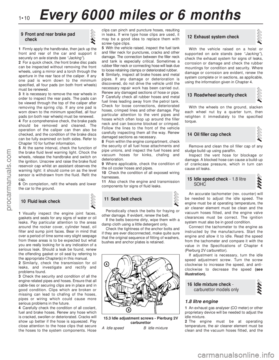
If adjustment is necessary, turn the idle
speed adjustment screw. Turn the screw
clockwise to increase the speed, and anti-
clockwise to decrease the speed (see
illustration).
1.8 litre engine
1An exhaust gas analyser (CO meter) or other
proprietary device will be needed to adjust the
idle mixture.
2The engine must be at operating
temperature, the air cleaner element must be
clean and the vacuum hoses fitted, and the
16Idle mixture check -
carburettor models only
15Idle speed check - 1.8 litre
SOHC
14Oil filler cap check
13Roadwheel security check
12Exhaust system check
11Seat belt check10Fluid leak check
9Front and rear brake pad
check
1•10Every 6000 miles or 6 months
15.3 Idle adjustment screws - Pierburg 2V
carburettor
A Idle speedB Idle mixture
procarmanuals.com
Page 14 of 255
DOHC engines
12On this engine, the coolant/alternator
drivebelt also drives the power steering pump
and (where applicable) the air conditioning
compressor. The drivebelt tension is set by an
automatic tensioner assembly.
13The condition of the drivebelt should be
checked as described above.
14An idea of the amount of wear which has
taken place on the belt can be gained from the
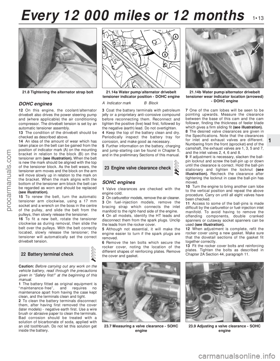
position of indicator mark (A) on the mounting
bracket in relation to the block (B) on the
tensioner arm (see illustration).When the belt
is new the mark should be aligned with the top
of the tensioner block. As the belt wears, the
tensioner arm moves and the block on the arm
will move slowly up in relation to the mark on
the bracket. When the mark aligns with the
bottom of the tensioner arm block the belt can
be regarded as worn and should be replaced
(see illustration).
15To renew the belt, turn the automatic
tensioner arm clockwise, using a 17 mm
socket and a wrench on the boss in the centre
of the pulley, and slide the belt from the
pulleys, then slowly release the tensioner.
16To fit a new belt, rotate the tensioner
clockwise as during removal, then slide the
belt over the pulleys. With the belt correctly
located, slowly release the tensioner; the
tensioner will automatically set the correct
drivebelt tension.
Caution:Before carrying out any work on the
vehicle battery, read through the precautions
given in “Safety first!” at the beginning of this
manual.
1The battery fitted as original equipment is
“maintenance-free”, and requires no
maintenance apart from having the case kept
clean, and the terminals clean and tight.
2To clean the battery terminals disconnect
them, after having first removed the cover
(later models) -negative earth first. Use a wire
brush or abrasive paper to clean the terminals.
Bad corrosion should be treated with a
solution of bicarbonate of soda, applied with
an old toothbrush. Do not let this solution get
inside the battery.3Coat the battery terminals with petroleum
jelly or a proprietary anti-corrosive compound
before reconnecting them. Reconnect and
tighten the positive (live) lead first, followed by
the negative (earth) lead. Do not overtighten.
4Keep the top of the battery clean and dry.
Periodically inspect the battery tray for
corrosion, and make good as necessary.
5Further information on the battery, charging
and jump-starting can be found in Chapter 5,
and in the preliminary Sections of this manual.
SOHC engines
1Valve clearances are checked with the
engine cold.
2On carburettor models, remove the air cleaner.
3On fuel-injection models, remove the
bracing strap which connects the inlet
manifold to the right-hand side of the engine.
4On all models, identify the HT leads and
disconnect them from the spark plugs. Unclip
the leads from the rocker cover.
5Although not essential, it will make the
engine easier to turn if the spark plugs are
removed.
6Remove the ten bolts which secure the
rocker cover, noting the location of the
different shapes of reinforcing plates. Remove
the cover and gasket.7One of the cam lobes will be seen to be
pointing upwards. Measure the clearance
between the base of this cam and the cam
follower, finding the thickness of feeler blade
which gives a firm sliding fit(see illustration).
8The desired valve clearances are given in
the Specifications. Note that the clearances
for inlet and exhaust valves are different.
Numbering from the front (sprocket) end of the
camshaft, the exhaust valves are 1, 3, 5 and 7,
and the inlet valves 2, 4, 6 and 8.
9If adjustment is necessary, slacken the ball-
pin locknut and screw the ball-pin up or down
until the clearance is correct. Hold the ball-pin
stationary and tighten the locknut(see
illustration).Recheck the clearance after
tightening the locknut in case the ball-pin has
moved.
10Turn the engine to bring another cam lobe
to the vertical position and repeat the above
procedure. Carry on until all eight valves have
been checked.
11Access to some of the ball-pins is made
difficult by the carburettor or fuel-injection inlet
manifold. To avoid having to remove the
offending components, double cranked
spanners or cutaway socket spanners can be
used (see illustration).
12When adjustment is complete, refit the
rocker cover using a new gasket. Make sure
that the dovetail sections of the gasket fit
together correctly.
13Fit the rocker cover bolts and reinforcing
plates. Tighten the bolts as described in
Chapter 2A Section 44, paragraph 11.
23Engine valve clearance check
22Battery terminal check
1•13
1
Every 12 000 miles or 12 months
21.14a Water pump/alternator drivebelt
tensioner indicator position - DOHC engine
A Indicator markB Block
21.14b Water pump/alternator drivebelt
tensioner wear indicator location (arrowed)
- DOHC engine21.8 Tightening the alternator strap bolt
23.7 Measuring a valve clearance - SOHC
engine23.9 Adjusting a valve clearance - SOHC
engine
procarmanuals.com
Page 15 of 255
14Refit the other disturbed components.
15Run the engine and check that there are
no oil leaks from the rocker cover.
2.8 litre engine
16If the engine is in the vehicle, carry out the
preliminary steps:
a)Disconnect the battery negative lead
b)Remove the throttle mechanism cover, air
cleaner cover, airflow meters and inlet
trunking
c)Remove the HT leads from the spark plugs
and unclip them from the rocker cover
d)Unbolt and remove the rocker covers
17Although not essential, it will be easier to
turn the engine if the spark plugs are removed.
18Valve clearances must be adjusted with
the engine cold (less than 40°C/104°F).
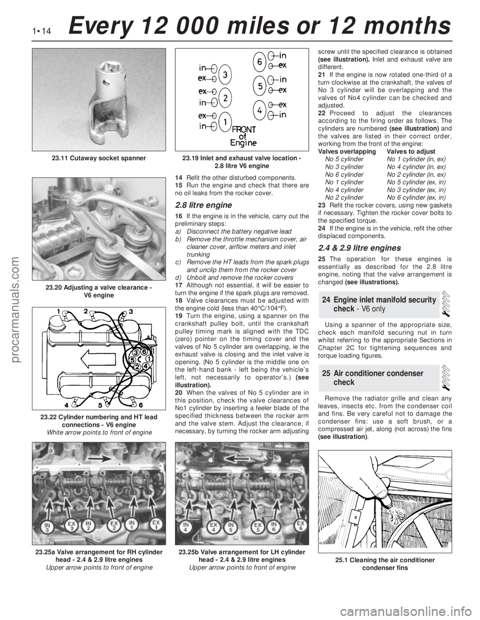
19Turn the engine, using a spanner on the
crankshaft pulley bolt, until the crankshaft
pulley timing mark is aligned with the TDC
(zero) pointer on the timing cover and the
valves of No 5 cylinder are overlapping, ie the
exhaust valve is closing and the inlet valve is
opening. (No 5 cylinder is the middle one on
the left-hand bank - left being the vehicle’s
left, not necessarily to operator’s.) (see
illustration).
20When the valves of No 5 cylinder are in
this position, check the valve clearances of
No1 cylinder by inserting a feeler blade of the
specified thickness between the rocker arm
and the valve stem. Adjust the clearance, if
necessary, by turning the rocker arm adjustingscrew until the specified clearance is obtained
(see illustration).Inlet and exhaust valve are
different.
21If the engine is now rotated one-third of a
turn clockwise at the crankshaft, the valves of
No 3 cylinder will be overlapping and the
valves of No4 cylinder can be checked and
adjusted.
22Proceed to adjust the clearances
according to the firing order as follows. The
cylinders are numbered (see illustration)and
the valves are listed in their correct order,
working from the front of the engine:
Valves overlappingValves to adjust
No 5 cylinderNo 1 cylinder (in, ex)
No 3 cylinderNo 4 cylinder (in, ex)
No 6 cylinderNo 2 cylinder (in, ex)
No 1 cylinderNo 5 cylinder (ex, in)
No 4 cylinderNo 3 cylinder (ex, in)
No 2 cylinderNo 6 cylinder (ex, in)
23Refit the rocker covers, using new gaskets
if necessary. Tighten the rocker cover bolts to
the specified torque.
24If the engine is in the vehicle, refit the other
displaced components.
2.4 & 2.9 litre engines
25The operation for these engines is
essentially as described for the 2.8 litre
engine, noting that the valve arrangement is
changed (see illustrations).
Using a spanner of the appropriate size,
check each manifold securing nut in turn
whilst referring to the appropriate Sections in
Chapter 2C for tightening sequences and
torque loading figures.
Remove the radiator grille and clean any
leaves, insects etc. from the condenser coil
and fins. Be very careful not to damage the
condenser fins: use a soft brush, or a
compressed air jet, along (not across) the fins
(see illustration).
25Air conditioner condenser
check
24Engine inlet manifold security
check - V6 only
1•14Every 12 000 miles or 12 months
23.19 Inlet and exhaust valve location -
2.8 litre V6 engine
23.20 Adjusting a valve clearance -
V6 engine
23.11 Cutaway socket spanner
23.25a Valve arrangement for RH cylinder
head - 2.4 & 2.9 litre engines
Upper arrow points to front of engine23.25b Valve arrangement for LH cylinder
head - 2.4 & 2.9 litre engines
Upper arrow points to front of engine
23.22 Cylinder numbering and HT lead
connections - V6 engine
White arrow points to front of engine
25.1 Cleaning the air conditioner
condenser fins
procarmanuals.com
Page 29 of 255
14Take the weight of the engine and remove
the two engine bearer-to-mounting nuts.
15Lift the engine/transmission, at the same
time lowering the trolley jack. Draw the unit
forwards and lift it out of the engine bay.
16Temporarily refit the anti-roll bar if the
vehicle is to be moved.
1With the engine and gearbox on the bench,
remove the starter motor.
2Remove the bolt from the engine adapter plate.
3Remove the bracing strap and the
remaining engine-to-bellhousing bolts.
4With the aid of an assistant draw the
gearbox off the engine. Do not allow the weight
of the gearbox to hang on the input shaft.
1It is best to mount the engine on a
dismantling stand, but if this is not available,
stand the engine on a strong bench at a
comfortable working height. Failing this, it will
have to be stripped down on the floor.
2Cleanliness is most important, and if the
engine is dirty, it should be cleaned with
paraffin while keeping it in an upright position.
3Avoid working with the engine on a concrete
floor, as grit can be a real source of trouble.
4As parts are removed, clean them in paraffin.
However, do not immerse parts with internal
oilways in paraffin as it is difficult to remove,
usually requiring a high pressure hose.
5It is advisable to have suitable containers to
hold small items according to their use, as this
will help when reassembling the engine and
also prevent possible losses.
6Always obtain complete sets of gaskets
when the engine is being dismantled, but
retain the old gaskets with a view of using
them as a pattern to make a replacement if a
new one is not available.7When possible, refit nuts, bolts and washers
in their location after being removed, as this
helps protect the threads and will also be
helpful when reassembling the engine.
8Retain unserviceable components in order
to compare them with the new parts supplied.
9A Torx key, size T55, will be needed for
dealing with the cylinder head bolts. A 12-
spline key (to fit bolt size M8) will be needed
for the oil pump bolts. Other Torx and 12-
spline bolts may be encountered; sets of the
keys required to deal with them are available
from most motor accessory shops and tool
factors.
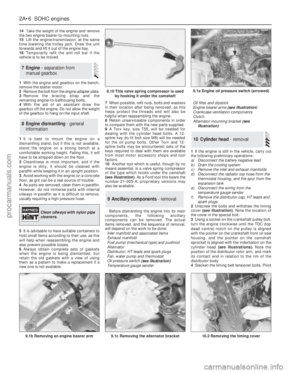
10Another tool which is useful, though by no
means essential, is a valve spring compressor
of the type which hooks under the camshaft
(see illustration). As a Ford tool this bears the
number 21-005-A; proprietary versions may
also be available.
Before dismantling the engine into its main
components, the following ancillary
components can be removed. The actual
items removed, and the sequence of removal,
will depend on the work to be done:
Inlet manifold and associated items
Exhaust manifold
Fuel pump (mechanical type) and pushrod
Alternator
Distributor, HT leads and spark plugs
Fan, water pump and thermostat
Oil pressure switch
(see illustration)
Temperature gauge senderOil filter and dipstick
Engine bearer arms (see illustration)
Crankcase ventilation components
Clutch
Alternator mounting bracket (see
illustration)
1If the engine is still in the vehicle, carry out
the following preliminary operations:
a)Disconnect the battery negative lead
b)Drain the cooling system
c)Remove the inlet and exhaust manifolds
d)Disconnect the radiator top hose from the
thermostat housing, and the spur from the
expansion tank
e)Disconnect the wiring from the
temperature gauge sender
f)Remove the distributor cap, HT leads and
spark plugs
2Unscrew the bolts and withdraw the timing
cover (see illustration). Note the location of
the cover in the special bolt.
3Using a socket on the crankshaft pulley bolt.
turn the engine clockwise until the TDC (top
dead centre) notch on the pulley is aligned
with the pointer on the crankshaft front oil seal
housing, and the pointer on the camshaft
sprocket is aligned with the indentation on the
cylinder head (see illustrations).Note the
position of the distributor rotor arm, and mark
its contact end in relation to the rim of the
distributor body.
4Slacken the timing belt tensioner bolts. Pivot
10Cylinder head - removal
9Ancillary components - removal
8Engine dismantling - general
information
7Engine - separation from
manual gearbox
2A•6SOHCengines
9.1a Engine oil pressure switch (arrowed)
9.1b Removing an engine bearer arm9.1c Removing the alternator bracket
8.10 This valve spring compressor is used
by hooking it under the camshaft
Clean oilways with nylon pipe
cleaners.
10.2 Removing the timing cover
procarmanuals.com
Page 31 of 255
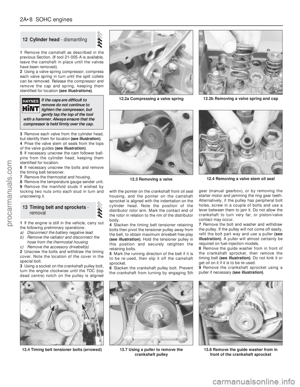
1Remove the camshaft as described in the
previous Section. (If tool 21-005-A is available,
leave the camshaft in place until the valves
have been removed).
2Using a valve spring compressor, compress
each valve spring in turn until the split collets
can be removed. Release the compressor and
remove the cap and spring, keeping them
identified for location (see illustrations).
3Remove each valve from the cylinder head,
but identify them for location (see illustration).
4Prise the valve stem oil seals from the tops
of the valve guides (see illustration).
5If necessary unscrew the cam follower ball-
pins from the cylinder head, keeping them
identified for location.
6If necessary unscrew the bolts and remove
the timing belt tensioner.
7Remove the thermostat and housing.
8Remove the temperature gauge sender unit.
9Remove the manifold studs if wished by
locking two nuts onto each stud in turn and
unscrewing it.
1If the engine is still in the vehicle, carry out
the following preliminary operations:
a)Disconnect the battery negative lead
b)Remove the radiator and disconnect the
hose from the thermostat housing
c)Remove the accessory drivebelt(s)
2Unscrew the bolts and withdraw the timing
cover. Note the location of the cover in the
special bolt.
3Using a socket on the crankshaft pulley bolt,
turn the engine clockwise until the TDC (top
dead centre) notch on the pulley is alignedwith the pointer on the crankshaft front oil seal
housing, and the pointer on the camshaft
sprocket is aligned with the indentation on the
cylinder head. Note the position of the
distributor rotor arm. Mark the contact end of
the rotor in relation to the rim of the distributor
body.
4Slacken the timing belt tensioner retaining
bolts then pivot the tensioner pulley away from
the belt, to obtain maximum drivebelt free play
(see illustration). Hold the tensioner pulley in
this position and securely retighten the
retaining bolts.
5Mark the running direction of the belt if it is
to be re-used, then slip it off the camshaft
sprocket.
6Slacken the crankshaft pulley bolt. Prevent
the crankshaft from turning by engaging 5thgear (manual gearbox), or by removing the
starter motor and jamming the ring gear teeth.
Alternatively, if the pulley has peripheral bolt
holes, screw in a couple of bolts and use a
lever between them to jam it. Do not allow the
crankshaft to turn very far, or piston/valve
contact may occur.
7Remove the bolt and washer and withdraw
the pulley. If the pulley will not come off easily,
refit the bolt part way and use a puller (see
illustration). A puller will almost certainly be
required on fuel-injection models.
8Remove the guide washer from in front of
the crankshaft sprocket, then remove the
timing belt (see illustration). Do not kink it or
get oil on it if it is to be re-used.
9Remove the crankshaft sprocket using a
puller if necessary (see illustration).
13Timing belt and sprockets -
removal
12Cylinder head - dismantling
2A•8SOHCengines
12.2a Compressing a valve spring
13.4 Timing belt tensioner bolts (arrowed)13.7 Using a puller to remove the
crankshaft pulley
12.4 Removing a valve stem oil seal
13.8 Remove the guide washer from in
front of the crankshaft sprocket
12.2b Removing a valve spring and cap
12.3 Removing a valve
If the caps are difficult to
remove do not continue to
tighten the compressor, but
gently tap the top of the tool
with a hammer. Always ensure that the
compressor is held firmly over the cap.
procarmanuals.com
Page 41 of 255
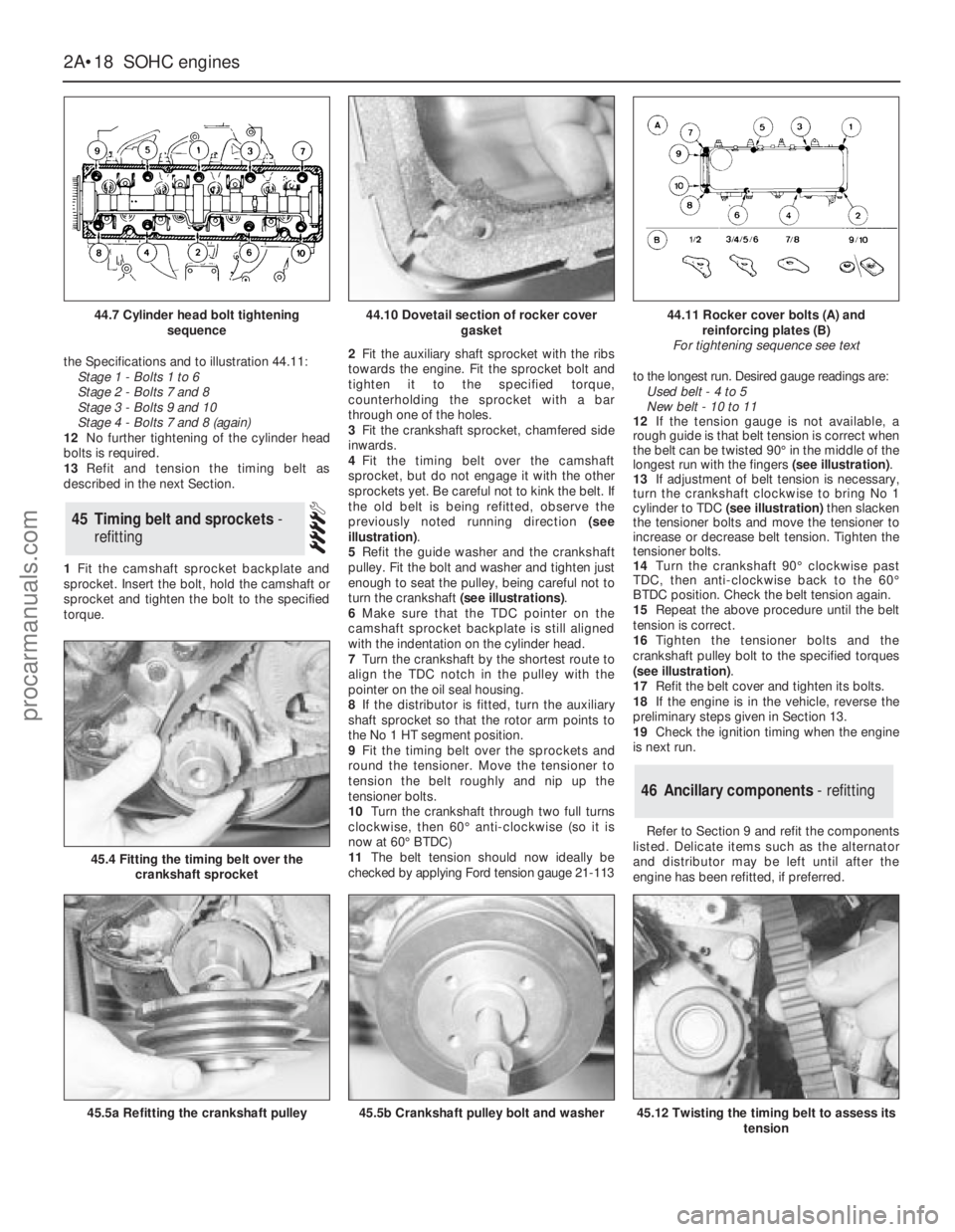
the Specifications and to illustration 44.11:
Stage 1 - Bolts 1 to 6
Stage 2 - Bolts 7 and 8
Stage 3 - Bolts 9 and 10
Stage 4 - Bolts 7 and 8 (again)
12No further tightening of the cylinder head
bolts is required.
13Refit and tension the timing belt as
described in the next Section.
1Fit the camshaft sprocket backplate and
sprocket. Insert the bolt, hold the camshaft or
sprocket and tighten the bolt to the specified
torque. 2Fit the auxiliary shaft sprocket with the ribs
towards the engine. Fit the sprocket bolt and
tighten it to the specified torque,
counterholding the sprocket with a bar
through one of the holes.
3Fit the crankshaft sprocket, chamfered side
inwards.
4Fit the timing belt over the camshaft
sprocket, but do not engage it with the other
sprockets yet. Be careful not to kink the belt. If
the old belt is being refitted, observe the
previously noted running direction (see
illustration).
5Refit the guide washer and the crankshaft
pulley. Fit the bolt and washer and tighten just
enough to seat the pulley, being careful not to
turn the crankshaft (see illustrations).
6Make sure that the TDC pointer on the
camshaft sprocket backplate is still aligned
with the indentation on the cylinder head.
7Turn the crankshaft by the shortest route to
align the TDC notch in the pulley with the
pointer on the oil seal housing.
8If the distributor is fitted, turn the auxiliary
shaft sprocket so that the rotor arm points to
the No 1 HT segment position.
9Fit the timing belt over the sprockets and
round the tensioner. Move the tensioner to
tension the belt roughly and nip up the
tensioner bolts.
10Turn the crankshaft through two full turns
clockwise, then 60°anti-clockwise (so it is
now at 60°BTDC)
11The belt tension should now ideally be
checked by applying Ford tension gauge 21-113to the longest run. Desired gauge readings are:
Used belt - 4 to 5
New belt - 10 to 11
12If the tension gauge is not available, a
rough guide is that belt tension is correct when
the belt can be twisted 90°in the middle of the
longest run with the fingers (see illustration).
13If adjustment of belt tension is necessary,
turn the crankshaft clockwise to bring No 1
cylinder to TDC(see illustration)then slacken
the tensioner bolts and move the tensioner to
increase or decrease belt tension. Tighten the
tensioner bolts.
14Turn the crankshaft 90°clockwise past
TDC, then anti-clockwise back to the 60°
BTDC position. Check the belt tension again.
15Repeat the above procedure until the belt
tension is correct.
16Tighten the tensioner bolts and the
crankshaft pulley bolt to the specified torques
(see illustration).
17Refit the belt cover and tighten its bolts.
18If the engine is in the vehicle, reverse the
preliminary steps given in Section 13.
19Check the ignition timing when the engine
is next run.
Refer to Section 9 and refit the components
listed. Delicate items such as the alternator
and distributor may be left until after the
engine has been refitted, if preferred.
46Ancillary components - refitting
45Timing belt and sprockets -
refitting
2A•18SOHCengines
44.7 Cylinder head bolt tightening
sequence
45.4 Fitting the timing belt over the
crankshaft sprocket
45.5a Refitting the crankshaft pulley45.5b Crankshaft pulley bolt and washer45.12 Twisting the timing belt to assess its
tension
44.10 Dovetail section of rocker cover
gasket44.11 Rocker cover bolts (A) and
reinforcing plates (B)
For tightening sequence see text
procarmanuals.com
Page 57 of 255
camshaft sprocket, aligning the marks made
previously on the chain and the sprocket.
40Fit the sprocket to the inlet camshaft, with
the camshaft in the TDC position (ie with the
inlet camshaft sprocket timing mark in line
with the top edge of the cylinder head,
pointing to the inlet side of the engine see
paragraph 4). Again, turn the camshaft if
necessary to enable the sprocket to be fitted.
41With the sprocket fitted, fit the distributor
rotor shaft to the end of the camshaft, and
tighten the securing bolt finger-tight. Note that
it is acceptable for the timing chain to sag
slightly between the two pulleys.
42Fit a new upper timing chain guide to the
plate at the front of the cylinder head.
43Turn the crankshaft clockwise until the
inlet camshaft begins to turn.
44If the chain tensioner plunger piston
protrudes from the cylinder, unlatch the piston by
pressing the chain tensioner arm down by hand.
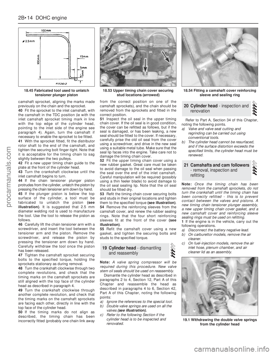
45If the plunger piston is below the top
surface of the cylinder, a tool must be
fabricated to unlatch the piston (see
illustration). It is suggested that 2.5 mm
diameter welding rod is used to manufacture
the tool. Use the tool to release the piston as
follows.
46Carefully lift the chain tensioner arm with a
screwdriver, and insert the tool between the
tensioner arm and the piston. Remove the
screwdriver, and release the piston by
pressing the tensioner arm down by hand.
Carefully withdraw the tool once the piston
has been released.
47Tighten the camshaft sprocket securing
bolts to the specified torque, holding the
sprockets stationary as during removal.
48Turn the crankshaft clockwise through two
complete revolutions, and check that the
timing marks on the camshaft sprockets are
still aligned with the top face of the cylinder
head as described in paragraph 4.
49Turn the crankshaft clockwise through
another complete revolution, and check that
the timing marks on the camshaft sprockets
are facing each other, directly in line with the
top face of the cylinder head.
50If the timing marks do not align as
described, the timing chain has been
incorrectly fitted (probably one chain link awayfrom the correct position on one of the
camshaft sprockets), and the chain should be
removed from the sprockets and fitted in the
correct position.
51Inspect the oil seal in the upper timing
chain cover. If the oil seal is in good condition,
the cover can be refitted as follows, but if the
seal is damaged, or has been leaking, a new
seal should be fitted to the cover. If necessary,
carefully prise the old oil seal from the cover
using a screwdriver, and drive in the new seal
using a suitable metal tube. Make sure that the
seal lip faces into the engine. Take care not to
damage the timing chain cover.
52Fit the upper timing chain cover using a
new rubber gasket. Great care must be taken
to avoid damage to the oil seal when passing
the seal over the end of the inlet camshaft.
Careful manipulation will be required (possibly
using a thin feeler blade) to avoid damage to
the oil seal sealing lip. Note that the oil seal
should be fitted dry.
53Refit the timing chain cover securing bolts
and studs in their original locations and tighten
them to the specified torque (see illustration).
54Remove the reinforcing sleeves from the
camshaft cover, and renew the rubber sealing
rings. Note that the four short reinforcing
sleeves fit at the front of the cover (see
illustration).
55Refit the camshaft cover using a new
gasket, and tighten the securing bolts and
studs to the specified torque.
Note: A valve spring compressor will be
required during this procedure. New valve
stem oil seals should be used on reassembly.
Dismantle the cylinder head as described in
paragraphs 2 to 4, Section 12, PartA of this
Chapterand reassemble the head as
described in paragraphs 4 to 6, Section 42,
Part A of this Chapter, noting the following
points:
a)Ignore the references to the special tool.
b)Double valve springs are used on all the
valves (see illustration).
c)Refer to the following Section if the
cylinder head is to be inspected and
renovated.Refer to Part A, Section 34 of this Chapter,
noting the following points.
a)Valve and valve seat cutting and
regrinding can be carried out using
conventional tools.
b)The cylinder head cannot be resurfaced,
and if the surface distortion exceeds the
specified limits, the cylinder head must be
renewed.
Note: Once the timing chain has been
removed from the camshaft sprockets, do not
turn the crankshaft until the timing chain has
been correctly refitted - this is to prevent
contact between the valves and pistons. A
new timing chain tensioner plunger assembly,
a new upper timing chain cover gasket, and a
new camshaft cover and reinforcing sleeve
sealing rings must be used on refitting.
1If the engine is in the vehicle, carry out the
following operations.
a)Disconnect the battery negative lead.
b)On carburettor models, remove the air
cleaner.
c)On fuel-injection models, remove the air
inlet hose, plenum chamber, and air
cleaner lid as an assembly.
21Camshafts and cam followers
- removal, inspection and
refitting
20Cylinder head - inspection and
renovation
19Cylinder head - dismantling
and reassembly
2B•14DOHCengine
18.45 Fabricated tool used to unlatch
tensioner plunger piston
19.1 Withdrawing the double valve springs
from the cylinder head
18.53 Upper timing chain cover securing
stud locations (arrowed)18.54 Fitting a camshaft cover reinforcing
sleeve and sealing ring
procarmanuals.com
Page 87 of 255
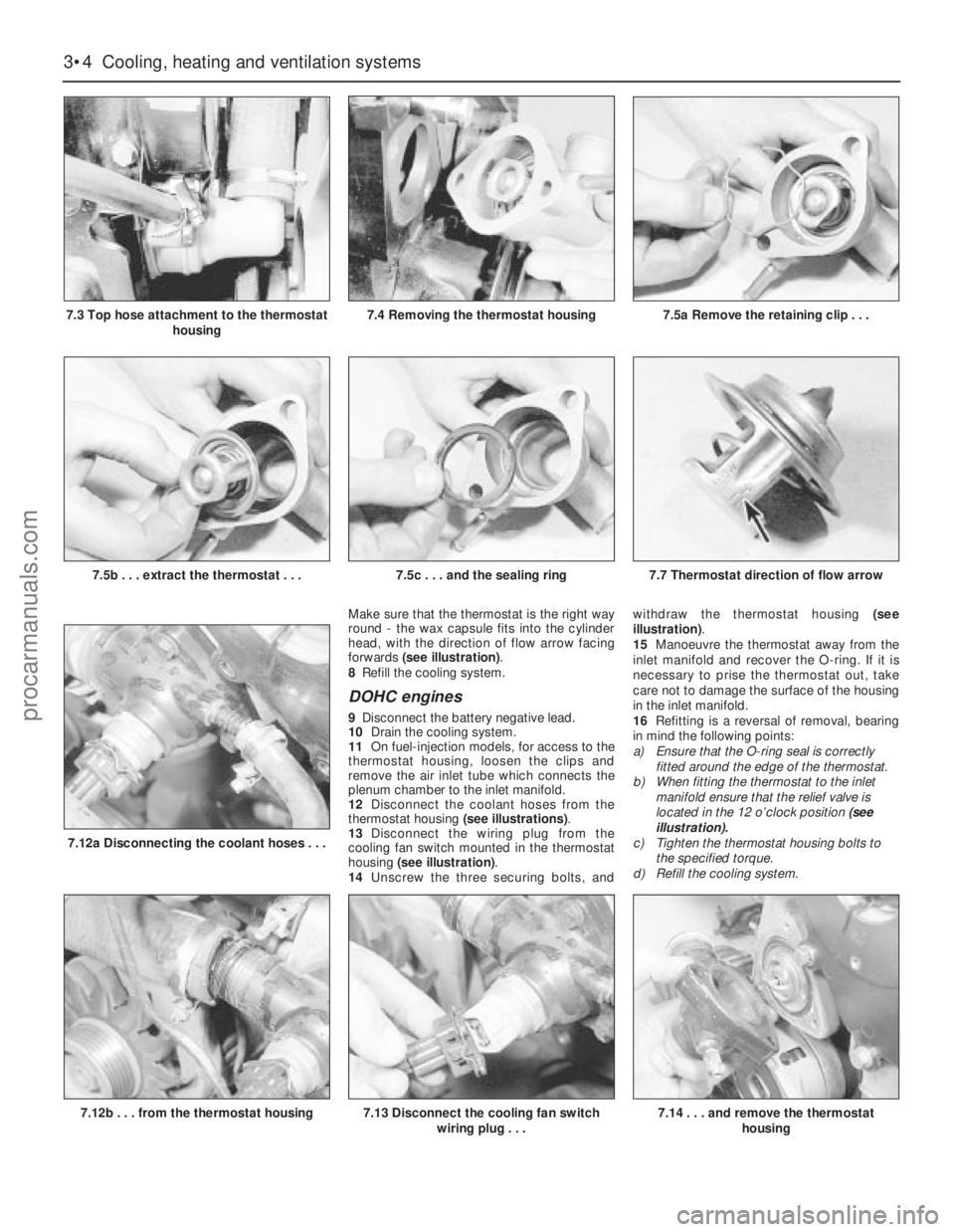
Make sure that the thermostat is the right way
round - the wax capsule fits into the cylinder
head, with the direction of flow arrow facing
forwards (see illustration).
8Refill the cooling system.
DOHC engines
9Disconnect the battery negative lead.
10Drain the cooling system.
11On fuel-injection models, for access to the
thermostat housing, loosen the clips and
remove the air inlet tube which connects the
plenum chamber to the inlet manifold.
12Disconnect the coolant hoses from the
thermostat housing (see illustrations).
13Disconnect the wiring plug from the
cooling fan switch mounted in the thermostat
housing (see illustration).
14Unscrew the three securing bolts, andwithdraw the thermostat housing (see
illustration).
15Manoeuvre the thermostat away from the
inlet manifold and recover the O-ring. If it is
necessary to prise the thermostat out, take
care not to damage the surface of the housing
in the inlet manifold.
16Refitting is a reversal of removal, bearing
in mind the following points:
a)Ensure that the O-ring seal is correctly
fitted around the edge of the thermostat.
b)When fitting the thermostat to the inlet
manifold ensure that the relief valve is
located in the 12 o’clock position (see
illustration).
c)Tighten the thermostat housing bolts to
the specified torque.
d)Refill the cooling system.
3•4Cooling, heating and ventilation systems
7.3 Top hose attachment to the thermostat
housing
7.12b . . . from the thermostat housing
7.5b . . . extract the thermostat . . .7.5c . . . and the sealing ring7.7 Thermostat direction of flow arrow
7.12a Disconnecting the coolant hoses . . .
7.13 Disconnect the cooling fan switch
wiring plug . . .7.14 . . . and remove the thermostat
housing
7.4 Removing the thermostat housing7.5a Remove the retaining clip . . .
procarmanuals.com