1985 FORD GRANADA clock
[x] Cancel search: clockPage 88 of 255
V6 engines
17The thermostat is removed in the course
of water pump removal.
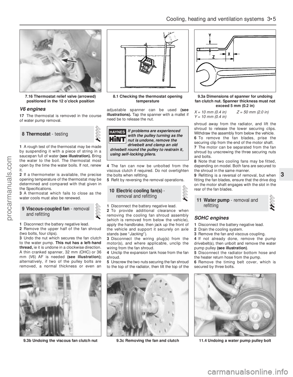
1A rough test of the thermostat may be made
by suspending it with a piece of string in a
saucepan full of water(see illustration).Bring
the water to the boil. The thermostat most
open by the time the water boils. If not, renew
it.
2If a thermometer is available, the precise
opening temperature of the thermostat may be
determined and compared with that given in
the Specifications.
3A thermostat which fails to close as the
water cools must also be renewed.
1Disconnect the battery negative lead.
2Remove the upper half of the fan shroud
(two bolts, four clips).
3Undo the nut which secures the fan clutch
to the water pump.This nut has a left-hand
thread, ie it is undone in a clockwise direction.
A thin cranked spanner, 32 mm (OHC) or 36
mm (V6) AF is needed(see illustration);
alternatively, if two of the pulley bolts are
removed, a normal thickness or even anadjustable spanner can be used (see
illustrations). Tap the spanner with a mallet if
need be to release the nut.
4The fan can now be unbolted from the
viscous clutch if required. Do not overtighten
the bolts when refitting.
5Refit by reversing the removal operations.
1Disconnect the battery negative lead.
2To provide additional clearance when
removing the cooling fan shroud assembly
(which is removed from below the vehicle),
apply the handbrake, then jack up the front of
the vehicle and support it securely on axle
stands (see “Jacking”).
3Disconnect the wiring plug(s) from the
motor(s), and where applicable, unclip the
wiring from the fan shroud.
4Unclip the expansion tank hose from the fan
shroud.
5Unscrew the two nuts securing the fan shroud
to the top of the radiator, then tilt the top of theshroud away from the radiator, and lift the
shroud to release the lower securing clips.
Withdraw the assembly from below the vehicle.
6To remove the fan blades, prise the
securing clip from the end of the motor shaft.
7The motor can be separated from the fan
shroud by unscrewing the three securing nuts
and bolts.
8Note that two cooling fans may be fitted,
depending on model. Both fans are secured to
the shroud in the same manner.
9Refitting is a reversal of removal, but when
fitting the fan blades, ensure that the drive dog
on the motor shaft engages with the slot in the
rear of the fan blades.
SOHC engines
1Disconnect the battery negative lead.
2Drain the cooling system.
3Remove the fan and viscous coupling.
4If not already done, remove the pump
drivebelt(s), then unbolt and remove the water
pump pulley (see illustration).
5Disconnect the radiator bottom hose and
the heater return hose from the pump.
6Remove the timing belt cover, which is
secured by three bolts.
11Water pump - removal and
refitting
10Electric cooling fan(s) -
removal and refitting
9Viscous-coupled fan - removal
and refitting
8Thermostat - testing
Cooling, heating and ventilation systems 3•5
3
7.16 Thermostat relief valve (arrowed)
positioned in the 12 o’clock position8.1 Checking the thermostat opening
temperature9.3a Dimensions of spanner for undoing
fan clutch nut. Spanner thickness must not
exceed 5 mm (0.2 in)
9.3b Undoing the viscous fan clutch nut9.3c Removing the fan and clutch11.4 Undoing a water pump pulley bolt
X = 10 mm (0.4 in)
Y = 10 mm (0.4 in)Z = 50 mm (2.0 in)
If problems are experienced
with the pulley turning as the
nut is undone, remove the
drivebelt and clamp an old
drivebelt round the pulley to restrain it,
using self-locking pliers.
procarmanuals.com
Page 93 of 255
towards the engine and remove the old
drivebelt.
5Fit the new drivebelt, position the
compressor to achieve the correct belt tension
and tighten the strap and pivot bolts.
6Refit and secure the fan, when applicable,
and reconnect the battery.
7Recheck the belt tension after it has run for
at least 10 minutes under load.
Condenser fan and motor
8Disconnect the battery earth lead and
remove the radiator grille.
9Disconnect the fan wiring connector at the
right-hand side of the condenser.
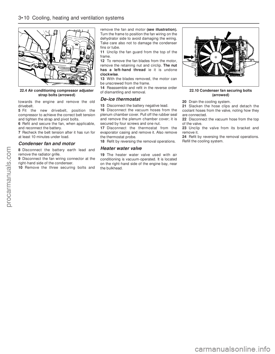
10Remove the three securing bolts andremove the fan and motor(see illustration).
Turn the frame to position the fan wiring on the
dehydrator side to avoid damaging the wiring.
Take care also not to damage the condenser
fins or tube.
11Unclip the fan guard from the top of the
frame.
12To remove the fan blades from the motor,
remove the retaining nut and circlip. The nut
has a left-hand threadie it is undone
clockwise.
13With the blades removed, the motor can
be unscrewed from the frame.
14Reassemble and refit in the reverse order
of dismantling and removal.
De-ice thermostat
15Disconnect the battery negative lead.
16Disconnect the vacuum hoses from the
plenum chamber cover. Pull off the rubber seal
and remove the plenum chamber cover; it is
secured by four screws and one nut.
17Disconnect the thermostat from the
evaporator casing and remove it. Also remove
the thermostat probe.
18Refit by reversing the removal operations.
Heater water valve
19The heater water valve used with air
conditioning is vacuum-operated. It is located
on the right-hand side of the engine bay, near
the bulkhead. 20Drain the cooling system.
21Slacken the hose clips and detach the
coolant hoses from the valve, noting how they
are connected.
22Disconnect the vacuum hose from the top
of the valve.
23Unclip the valve from its bracket and
remove it.
24Refit by reversing the removal operations.
Refill the cooling system.
3•10Cooling, heating and ventilation systems
22.4 Air conditioning compressor adjuster
strap bolts (arrowed)22.10 Condenser fan securing bolts
(arrowed)
procarmanuals.com
Page 102 of 255
1Check the cost and availability of spare parts
before deciding to dismantle the carburettor. If
the unit has seen much service, fitting a new or
reconditioned carburettor may prove more
satisfactory than any attempt at overhaul.
2Obtain a carburettor repair kit, which will
contain the necessary gaskets, diaphragms
and other renewable items.
3With the carburettor removed from the
vehicle, clean it thoroughly externally and
place it on a clean worksurface.
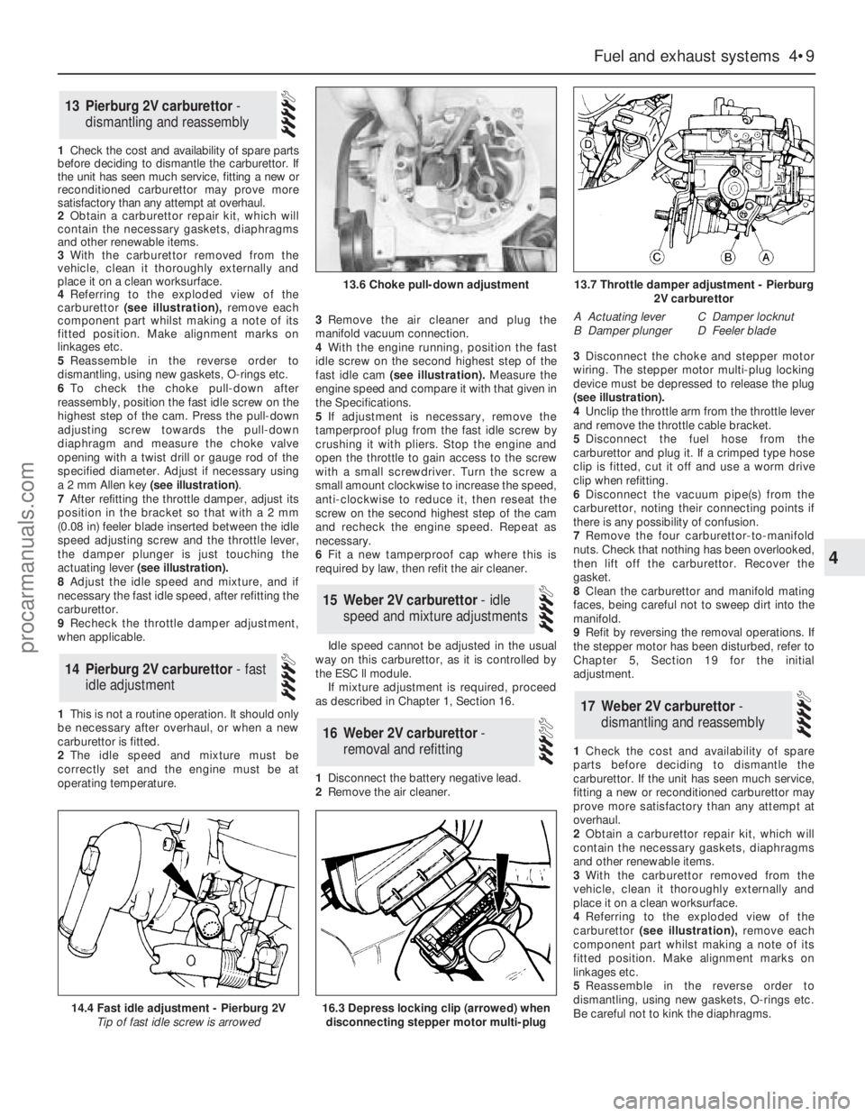
4 Referringto the exploded view of the
carburettor(see illustration),remove each
component part whilst making a note of its
fitted position. Make alignment marks on
linkages etc.
5Reassemble in the reverse order to
dismantling, using new gaskets, O-rings etc.
6To check the choke pull-down after
reassembly, position the fast idle screw on the
highest step of the cam. Press the pull-down
adjusting screw towards the pull-down
diaphragm and measure the choke valve
opening with a twist drill or gauge rod of the
specified diameter. Adjust if necessary using
a 2 mm Allen key (see illustration).
7After refitting the throttle damper, adjust its
position in the bracket so that with a 2 mm
(0.08 in) feeler blade inserted between the idle
speed adjusting screw and the throttle lever,
the damper plunger is just touching the
actuating lever(see illustration).
8Adjust the idle speed and mixture, and if
necessary the fast idle speed, after refitting the
carburettor.
9Recheck the throttle damper adjustment,
when applicable.
1This is not a routine operation. It should only
be necessary after overhaul, or when a new
carburettor is fitted.
2The idle speed and mixture must be
correctly set and the engine must be at
operating temperature.3Remove the air cleaner and plug the
manifold vacuum connection.
4With the engine running, position the fast
idle screw on the second highest step of the
fast idle cam(see illustration).Measure the
engine speed and compare it with that given in
the Specifications.
5If adjustment is necessary, remove the
tamperproof plug from the fast idle screw by
crushing it with pliers. Stop the engine and
open the throttle to gain access to the screw
with a small screwdriver. Turn the screw a
small amount clockwise to increase the speed,
anti-clockwise to reduce it, then reseat the
screw on the second highest step of the cam
and recheck the engine speed. Repeat as
necessary.
6Fit a new tamperproof cap where this is
required by law, then refit the air cleaner.
Idle speed cannot be adjusted in the usual
way on this carburettor, as it is controlled by
the ESC ll module.
If mixture adjustment is required, proceed
as described in Chapter 1, Section 16.
1Disconnect the battery negative lead.
2Remove the air cleaner.3Disconnect the choke and stepper motor
wiring. The stepper motor multi-plug locking
device must be depressed to release the plug
(seeillustration).
4Unclip the throttle arm from the throttle lever
and remove the throttle cable bracket.
5Disconnect the fuel hose from the
carburettor and plug it. If a crimped type hose
clip is fitted, cut it off and use a worm drive
clip when refitting.
6Disconnect the vacuum pipe(s) from the
carburettor, noting their connecting points if
there is any possibility of confusion.
7Remove the four carburettor-to-manifold
nuts. Check that nothing has been overlooked,
then lift off the carburettor. Recover the
gasket.
8Clean the carburettor and manifold mating
faces, being careful not to sweep dirt into the
manifold.
9Refit by reversing the removal operations. If
the stepper motor has been disturbed, refer to
Chapter 5, Section 19 for the initial
adjustment.
1Check the cost and availability of spare
parts before deciding to dismantle the
carburettor. If the unit has seen much service,
fitting a new or reconditioned carburettor may
prove more satisfactory than any attempt at
overhaul.
2Obtain a carburettor repair kit, which will
contain the necessary gaskets, diaphragms
and other renewable items.
3With the carburettor removed from the
vehicle, clean it thoroughly externally and
place it on a clean worksurface.
4 Referringto the exploded view of the
carburettor(see illustration),remove each
component part whilst making a note of its
fitted position. Make alignment marks on
linkages etc.
5Reassemble in the reverse order to
dismantling, using new gaskets, O-rings etc.
Be careful not to kink the diaphragms.
17Weber 2V carburettor -
dismantling and reassembly
16Weber 2V carburettor -
removal and refitting
15Weber 2V carburettor - idle
speed and mixture adjustments
14Pierburg 2V carburettor - fast
idle adjustment
13Pierburg 2V carburettor -
dismantling and reassembly
Fuel and exhaust systems 4•9
4
14.4 Fast idle adjustment - Pierburg 2V
Tip of fast idle screw is arrowed
13.6 Choke pull-down adjustment13.7 Throttle damper adjustment - Pierburg
2V carburettor
A Actuating lever
B Damper plungerC Damper locknut
D Feeler blade
16.3 Depress locking clip (arrowed) when
disconnecting stepper motor multi-plug
procarmanuals.com
Page 107 of 255
16Start the engine and note the engine
speed (rpm). The engine speed should
increase above the normal idle speed, and
should be as given in the Specifications.
17If the engine speed is not as specified,
remove the tamperproof plug from the top of
the throttle kicker housing, and turn the
adjustment screw to give the specified speed.
18On completion of adjustment, fit a new
tamperproof cap.
19Disconnect the tubing from the inlet
manifold, and reconnect the throttle kicker
vacuum hose.
20Refit the plastic shield and the air cleaner.
On 2.4 & 2.9 litre V6 models especially,
residual pressure will remain in the fuel lines
long after the vehicle was last used therefore
the fuel system must be depressurised before
any hose is disconnected; the system is
depressurised via the vent valve on the fuel
rail, noting that it may be necessary to depress
the valve several times before the pressure is
fully released. As an added precaution place a
rag over the valve as it is depressed to catch
any fuel which is forcibly expelled. Before
carrying out any operation on the fuel system
refer to the precautions given in Safety first! at
the beginning of this Manual and follow them
implicitly. Petrol is a highly dangerous and
volatile liquid and the precautions necessary
when handling it cannot be overstressed.
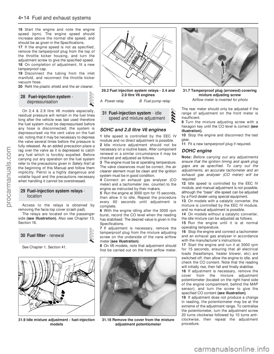
Access to the relays is obtained by
removing the facia top cover (crash pad).
The relays are located on the passenger
side(see illustration). Also see Chapter 13,
Section 16.
See Chapter 1, Section 41.
SOHC and 2.8 litre V6 engines
1Idle speed is controlled by the EEC IV
module and no direct adjustment is possible.
2Idle mixture adjustment should not be
necessary on a routine basis. After component
renewal or a similar circumstance it may be
checked and adjusted as follows.
3The engine must be at operating temperature.
The valve clearances must be correct, the air
cleaner element must be clean and the ignition
system must be in good condition.
4Connect an exhaust gas analyser (CO
meter) and a tachometer (rev. counter) to the
engine as instructed by their makers.
5Run the engine at 3000 rpm for 15 seconds,
then allow it to idle. Repeat the procedure
every 60 seconds until adjustment is
complete.
6With the engine idling after the 3000 rpm
burst, record the CO level when the reading
has stabilised. The desired value is given in the
Specifications.
7If adjustment is necessary, remove the
tamperproof plug from the mixture adjusting
screw on the underside of the vane airflow
meter (see illustration).
8On V6 models, note that adjustment should
first be carried out on the front airflow meter.The rear meter should only be adjusted if the
range of adjustment on the front meter is
insufficient.
9Turn the mixture adjusting screw with a
hexagon key until the CO level is correct (see
illustration).
10Stop the engine and disconnect the test
gear.
11Fit a new tamperproof plug if required.
DOHC engine
Note: Before carrying out any adjustments
ensure that the ignition timing and spark plug
gaps are as specified. To carry out the
adjustments, an accurate tachometer and an
exhaust gas analyser (CO meter) will be
required.
12Idle speed is controlled by the EEC IV
module, and manual adjustment is not possible,
although the “base” idle speed can be adjusted
by a Ford dealer using special equipment.
13On models with a catalytic converter, the
mixture is controlled by the EEC IV module,
and no manual adjustment is possible.
14On models without a catalytic converter,
the idle mixture can be adjusted as follows.
15Run the engine until it is at normal
operating temperature.
16Stop the engine and connect a tachometer
and an exhaust gas analyser in accordance
with the manufacturer’s instructions.
17Start the engine and run it at 3000 rpm
for 15 seconds, ensuring that all electrical
loads (headlamps, heater blower, etc) are
switched off, then allow the engine to idle, and
check the CO content. Note that the reading
will initially rise, then fall and finally stabilise.
18If adjustment is necessary, remove the
cover from the mixture adjustment
potentiometer (located on the right-hand side
of the engine compartment, behind the MAP
sensor), and turn the screw to give the
specified CO content (see illustration).
19If adjustment does not produce a change
in reading, the potentiometer may be at the
extreme of the adjustment range. To centralise
the potentiometer, turn the adjustment screw
20 turns clockwise followed by 10 turns anti-
clockwise, then repeat the adjustment
procedure.
31Fuel-injection system - idle
speed and mixture adjustment
30Fuel filter - renewal
29Fuel-injection system relays -
location
28Fuel-injection system -
depressurisation
4•14Fuel and exhaust systems
31.18 Remove the cover from the mixture
adjustment potentiometer31.9 Idle mixture adjustment - fuel-injection
models
29.2 Fuel injection system relays - 2.4 and
2.9 litre V6 engines
A Power relayB Fuel pump relay
31.7 Tamperproof plug (arrowed) covering
mixture adjusting screw
Airflow meter is inverted for photo
procarmanuals.com
Page 119 of 255
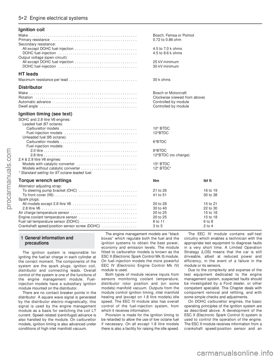
The ignition system is responsible for
igniting the fuel/air charge in each cylinder at
the correct moment. The components of the
system are the spark plugs, ignition coil,
distributor and connecting leads. Overall
control of the system is one of the functions of
the engine management module. Fuel-
injection models have a subsidiary ignition
module mounted on the distributor.
There are no contact breaker points in the
distributor. A square wave signal is generated
by the distributor electro-magnetically; this
signal is used by the engine management
module as a basis for switching the coil LT
current. Speed-related (centrifugal) advance is
also handled by the module. On carburettor
models, ignition timing is also advanced under
conditions of high inlet manifold vacuum.The engine management models are “black
boxes” which regulate both the fuel and the
ignition systems to obtain the best power,
economy and emission levels. The module
fitted to carburettor models is known as the
ESC II (Electronic Spark Control Mk II) module.
On fuel-injection models the more powerful
EEC IV (Electronic Engine Control Mk IV)
module is used.
Both types of module receive inputs from
sensors monitoring coolant temperature,
distributor rotor position and (on some
models) manifold vacuum. Outputs from the
module control ignition timing, inlet manifold
heating and (except on 1.8 litre models) idle
speed. The EEC IV module also has overall
control of the fuel-injection system, from
which it receives information.
Provision is made for the ignition timing to
be retarded to allow the use of low octane fuel
if necessary. On all except 1.8 litre models
there is also a facility for raising the idle speed.The EEC IV module contains self-test
circuitry which enables a technician with the
appropriate test equipment to diagnose faults
in a very short time. A Limited Operation
Strategy (LOS) means that the car is still
driveable, albeit at reduced power and
efficiency, in the event of a failure in the
module or its sensors.
Due to the complexity and expense of the
test equipment dedicated to the engine
management system, suspected faults should
be investigated by a Ford dealer, or other
competent specialist. This Chapter deals with
component removal and refitting, and with
some simple checks and adjustments.
On DOHC carburettor engines, the basic
operating principles of the ignition system are
as described above. A development of the
ESC II (Electronic Spark Control ll) system is
used to control the operation of the engine.
The ESC II module receives information from a
crankshaft speed/position sensor and an
1General information and
precautions
5•2Engine electrical systems
Ignition coil
Make . . . . . . . . . . . . . . . . . . . . . . . . . . . . . . . . . . . . . . . . . . . . . . . . . . . .Bosch, Femsa or Polmot
Primary resistance . . . . . . . . . . . . . . . . . . . . . . . . . . . . . . . . . . . . . . . . .0.72 to 0.86 ohm
Secondary resistance:
All except DOHC fuel-injection . . . . . . . . . . . . . . . . . . . . . . . . . . . . . .4.5 to 7.0 k ohms
DOHC fuel-injection . . . . . . . . . . . . . . . . . . . . . . . . . . . . . . . . . . . . . .4.5 to 8.6 k ohms
Output voltage (open-circuit):
All except DOHC fuel-injection . . . . . . . . . . . . . . . . . . . . . . . . . . . . . .25 kV minimum
DOHC fuel-injection . . . . . . . . . . . . . . . . . . . . . . . . . . . . . . . . . . . . . .30 kV minimum
HT leads
Maximum resistance per lead . . . . . . . . . . . . . . . . . . . . . . . . . . . . . . . . .30 k ohms
Distributor
Make . . . . . . . . . . . . . . . . . . . . . . . . . . . . . . . . . . . . . . . . . . . . . . . . . . . .Bosch or Motorcraft
Rotation . . . . . . . . . . . . . . . . . . . . . . . . . . . . . . . . . . . . . . . . . . . . . . . . .Clockwise (viewed from above)
Automatic advance . . . . . . . . . . . . . . . . . . . . . . . . . . . . . . . . . . . . . . . . .Controlled by module
Dwell angle . . . . . . . . . . . . . . . . . . . . . . . . . . . . . . . . . . . . . . . . . . . . . . .Controlled by module
Ignition timing (see text)
SOHC and 2.8 litre V6 engines:
Leaded fuel (97 octane):
Carburettor models . . . . . . . . . . . . . . . . . . . . . . . . . . . . . . . . . . . . .10°BTDC
Fuel-injection models . . . . . . . . . . . . . . . . . . . . . . . . . . . . . . . . . . .12°BTDC
Unleaded fuel (95 octane):
Carburettor models . . . . . . . . . . . . . . . . . . . . . . . . . . . . . . . . . . . . .6°BTDC
Fuel-injection models:
2.0 litre . . . . . . . . . . . . . . . . . . . . . . . . . . . . . . . . . . . . . . . . . . . . .8°BTDC
2.8 litre . . . . . . . . . . . . . . . . . . . . . . . . . . . . . . . . . . . . . . . . . . . . .12°BTDC (no change)
2.4 & 2.9 litre V6 engines:
Models with catalytic converter . . . . . . . . . . . . . . . . . . . . . . . . . . . . .15°BTDC
Models without catalytic converter . . . . . . . . . . . . . . . . . . . . . . . . . . .12°BTDC*
* Standard setting for 97 octane leaded fuel.
Torque wrench settingsNmlbf ft
Alternator adjusting strap:
To steering pump bracket (OHC) . . . . . . . . . . . . . . . . . . . . . . . . . . . .21 to 2616 to 19
To front cover (V6) . . . . . . . . . . . . . . . . . . . . . . . . . . . . . . . . . . . . . . . .41 to 5130 to 38
Spark plugs:
All models except 2.8 litre V6 . . . . . . . . . . . . . . . . . . . . . . . . . . . . . . .20 to 2815 to 21
2.8 litre V6 . . . . . . . . . . . . . . . . . . . . . . . . . . . . . . . . . . . . . . . . . . . . . .30 to 4022 to 30
Air charge temperature sensor . . . . . . . . . . . . . . . . . . . . . . . . . . . . . . . .20 to 2515 to 18
Engine coolant temperature sensor . . . . . . . . . . . . . . . . . . . . . . . . . . . .20 to 2515 to 18
Fuel rail temperature sensor (DOHC) . . . . . . . . . . . . . . . . . . . . . . . . . . .8 to 116 to 8
Crankshaft speed/position sensor screw (DOHC) . . . . . . . . . . . . . . . . .3 to 52 to 4
procarmanuals.com
Page 123 of 255
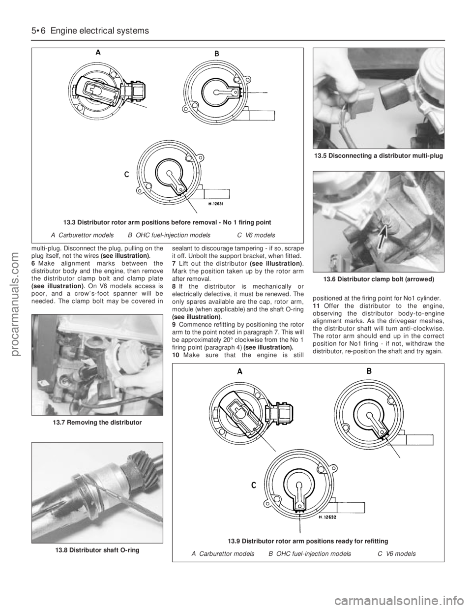
multi-plug. Disconnect the plug, pulling on the
plug itself, not the wires (see illustration).
6Make alignment marks between the
distributor body and the engine, then remove
the distributor clamp bolt and clamp plate
(see illustration). On V6 models access is
poor, and a crow’s-foot spanner will be
needed. The clamp bolt may be covered insealant to discourage tampering - if so, scrape
it off. Unbolt the support bracket, when fitted.
7Lift out the distributor (see illustration).
Mark the position taken up by the rotor arm
after removal.
8If the distributor is mechanically or
electrically defective, it must be renewed. The
only spares available are the cap, rotor arm,
module (when applicable) and the shaft O-ring
(see illustration).
9Commence refitting by positioning the rotor
arm to the point noted in paragraph 7. This will
be approximately 20°clockwise from the No 1
firing point (paragraph 4)(see illustration).
10Make sure that the engine is stillpositioned at the firing point for No1 cylinder.
11Offer the distributor to the engine,
observing the distributor body-to-engine
alignment marks. As the drivegear meshes,
the distributor shaft will turn anti-clockwise.
The rotor arm should end up in the correct
position for No1 firing - if not, withdraw the
distributor, re-position the shaft and try again.
5•6Engine electrical systems
13.6 Distributor clamp bolt (arrowed)
13.8 Distributor shaft O-ring
13.7 Removing the distributor
13.5 Disconnecting a distributor multi-plug
13.3 Distributor rotor arm positions before removal - No 1 firing point
A Carburettor modelsB OHC fuel-injection modelsC V6 models
13.9 Distributor rotor arm positions ready for refitting
A Carburettor modelsB OHC fuel-injection modelsC V6 models
procarmanuals.com
Page 125 of 255
6If adjustment is necessary, stop the engine.
Slacken the distributor clamp bolt and turn the
distributor body slightly. To retard the ignition
(move the mark nearer TDC) turn the
distributor body clockwise, and vice versato
advance the ignition. Tighten the clamp bolt
and re-check the timing.
7When adjustment is correct, stop the engine
and disconnect the timing light. Reconnect the
vacuum pipe, when applicable, and reconnect
any “octane adjustment” wires.
DOHC engine
8The ignition timing for this engine is
controlled by the ESC II or EEC IV module and
no adjustment is possible.
SOHC and 2.8 litre V6 engines
1Disconnect the battery negative lead.
2Disconnect the distributor multi-plug.
3On V6 models only, make alignment marks
between the distributor body and the engine.
Slacken the distributor clamp bolt and swivel
the distributor to make the module securing
screws accessible.
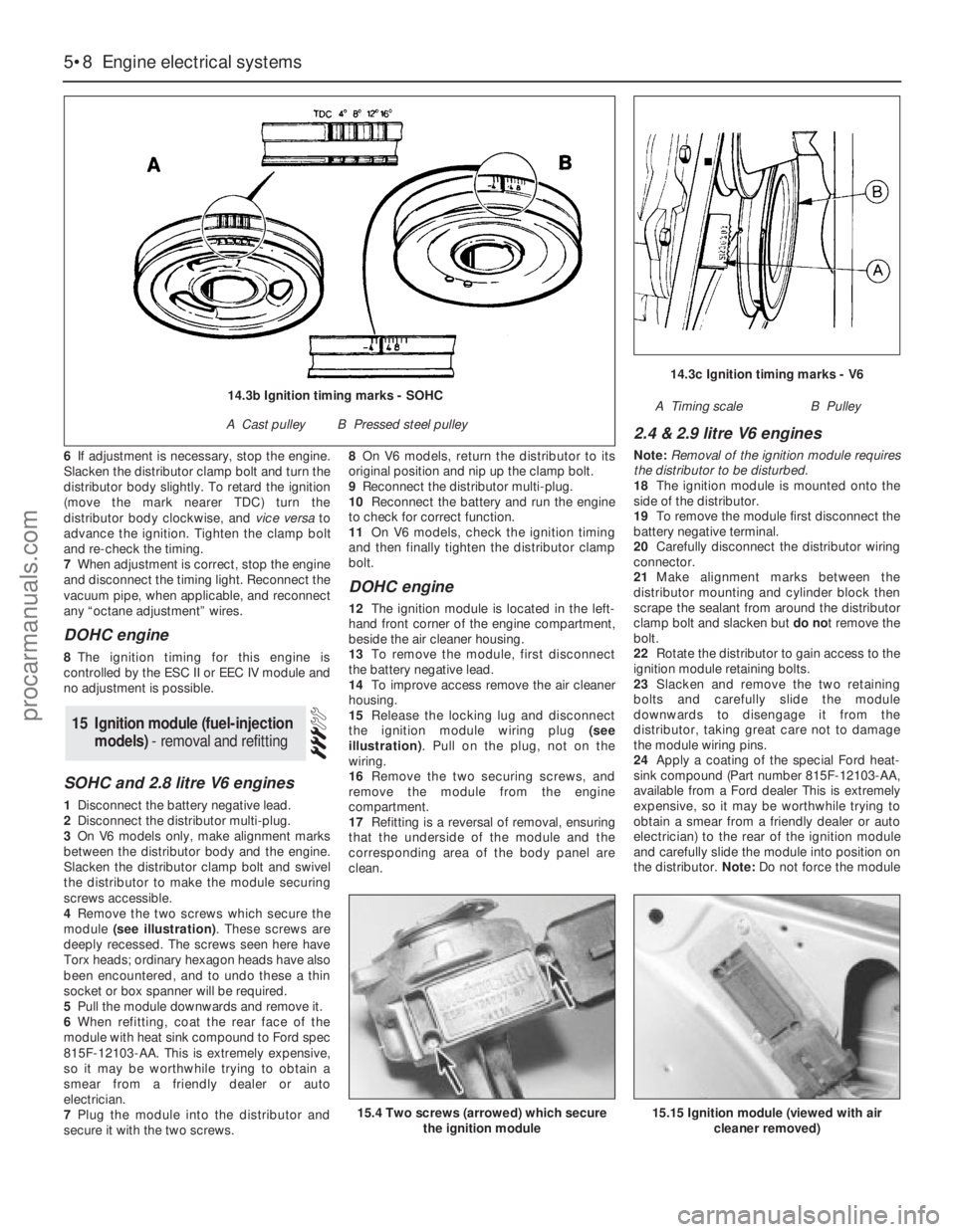
4Remove the two screws which secure the
module (see illustration). These screws are
deeply recessed. The screws seen here have
Torx heads; ordinary hexagon heads have also
been encountered, and to undo these a thin
socket or box spanner will be required.
5Pull the module downwards and remove it.
6When refitting, coat the rear face of the
module with heat sink compound to Ford spec
815F-12103-AA. This is extremely expensive,
so it may be worthwhile trying to obtain a
smear from a friendly dealer or auto
electrician.
7Plug the module into the distributor and
secure it with the two screws.8On V6 models, return the distributor to its
original position and nip up the clamp bolt.
9Reconnect the distributor multi-plug.
10Reconnect the battery and run the engine
to check for correct function.
11On V6 models, check the ignition timing
and then finally tighten the distributor clamp
bolt.
DOHC engine
12The ignition module is located in the left-
hand front corner of the engine compartment,
beside the air cleaner housing.
13To remove the module, first disconnect
the battery negative lead.
14To improve access remove the air cleaner
housing.
15Release the locking lug and disconnect
the ignition module wiring plug (see
illustration). Pull on the plug, not on the
wiring.
16Remove the two securing screws, and
remove the module from the engine
compartment.
17Refitting is a reversal of removal, ensuring
that the underside of the module and the
corresponding area of the body panel are
clean.
2.4 & 2.9 litre V6 engines
Note: Removal of the ignition module requires
the distributor to be disturbed.
18The ignition module is mounted onto the
side of the distributor.
19To remove the module first disconnect the
battery negative terminal.
20Carefully disconnect the distributor wiring
connector.
21Make alignment marks between the
distributor mounting and cylinder block then
scrape the sealant from around the distributor
clamp bolt and slacken but do not remove the
bolt.
22Rotate the distributor to gain access to the
ignition module retaining bolts.
23Slacken and remove the two retaining
bolts and carefully slide the module
downwards to disengage it from the
distributor, taking great care not to damage
the module wiring pins.
24Apply a coating of the special Ford heat-
sink compound (Part number 815F-12103-AA,
available from a Ford dealer This is extremely
expensive, so it may be worthwhile trying to
obtain a smear from a friendly dealer or auto
electrician) to the rear of the ignition module
and carefully slide the module into position on
the distributor. Note: Do not force the module
15Ignition module (fuel-injection
models) - removal and refitting
5•8Engine electrical systems
15.4 Two screws (arrowed) which secure
the ignition module15.15 Ignition module (viewed with air
cleaner removed)
14.3c Ignition timing marks - V6
A Timing scaleB Pulley14.3b Ignition timing marks - SOHC
A Cast pulleyB Pressed steel pulley
procarmanuals.com
Page 134 of 255
1It is necessary to remove the rear wheels in
order to inspect the rear pads. The pads can
be viewed through the top of the caliper after
removing the spring clip. If any one pad is
worn down to the minimum specified, all four
pads (on both rear wheels) must be renewed.
2Free the handbrake cable from its clip on
the suspension lower arm. Release the
handbrake.
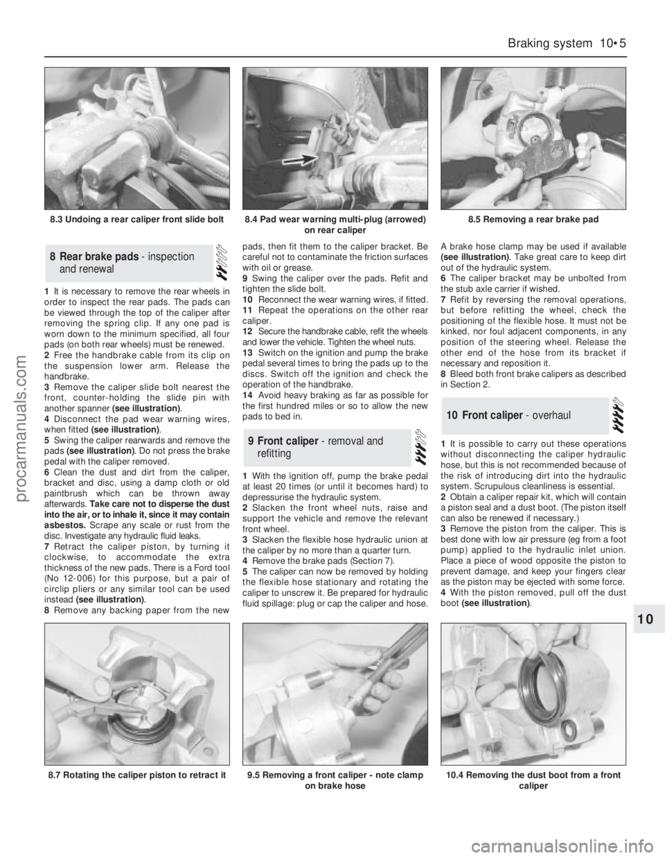
3Remove the caliper slide bolt nearest the
front, counter-holding the slide pin with
another spanner (see illustration).
4Disconnect the pad wear warning wires,
when fitted (see illustration).
5Swing the caliper rearwards and remove the
pads (see illustration). Do not press the brake
pedal with the caliper removed.
6Clean the dust and dirt from the caliper,
bracket and disc, using a damp cloth or old
paintbrush which can be thrown away
afterwards. Take care not to disperse the dust
into the air, or to inhale it, since it may contain
asbestos. Scrape any scale or rust from the
disc. Investigate any hydraulic fluid leaks.
7Retract the caliper piston, by turning it
clockwise, to accommodate the extra
thickness of the new pads. There is a Ford tool
(No 12-006) for this purpose, but a pair of
circlip pliers or any similar tool can be used
instead (see illustration).
8Remove any backing paper from the newpads, then fit them to the caliper bracket. Be
careful not to contaminate the friction surfaces
with oil or grease.
9Swing the caliper over the pads. Refit and
tighten the slide bolt.
10Reconnect the wear warning wires, if fitted.
11Repeat the operations on the other rear
caliper.
12Secure the handbrake cable, refit the wheels
and lower the vehicle. Tighten the wheel nuts.
13Switch on the ignition and pump the brake
pedal several times to bring the pads up to the
discs. Switch off the ignition and check the
operation of the handbrake.
14Avoid heavy braking as far as possible for
the first hundred miles or so to allow the new
pads to bed in.
1With the ignition off, pump the brake pedal
at least 20 times (or until it becomes hard) to
depressurise the hydraulic system.
2Slacken the front wheel nuts, raise and
support the vehicle and remove the relevant
front wheel.
3Slacken the flexible hose hydraulic union at
the caliper by no more than a quarter turn.
4Remove the brake pads (Section 7).
5The caliper can now be removed by holding
the flexible hose stationary and rotating the
caliper to unscrew it. Be prepared for hydraulic
fluid spillage: plug or cap the caliper and hose.A brake hose clamp may be used if available
(see illustration). Take great care to keep dirt
out of the hydraulic system.
6The caliper bracket may be unbolted from
the stub axle carrier if wished.
7Refit by reversing the removal operations,
but before refitting the wheel, check the
positioning of the flexible hose. It must not be
kinked, nor foul adjacent components, in any
position of the steering wheel. Release the
other end of the hose from its bracket if
necessary and reposition it.
8Bleed both front brake calipers as described
in Section 2.
1It is possible to carry out these operations
without disconnecting the caliper hydraulic
hose, but this is not recommended because of
the risk of introducing dirt into the hydraulic
system. Scrupulous cleanliness is essential.
2Obtain a caliper repair kit, which will contain
a piston seal and a dust boot. (The piston itself
can also be renewed if necessary.)
3Remove the piston from the caliper. This is
best done with low air pressure (eg from a foot
pump) applied to the hydraulic inlet union.
Place a piece of wood opposite the piston to
prevent damage, and keep your fingers clear
as the piston may be ejected with some force.
4With the piston removed, pull off the dust
boot (see illustration).
10Front caliper - overhaul
9Front caliper - removal and
refitting
8Rear brake pads - inspection
and renewal
Braking system 10•5
10
8.3 Undoing a rear caliper front slide bolt8.4 Pad wear warning multi-plug (arrowed)
on rear caliper8.5 Removing a rear brake pad
8.7 Rotating the caliper piston to retract it9.5 Removing a front caliper - note clamp
on brake hose10.4 Removing the dust boot from a front
caliper
procarmanuals.com