1985 FORD GRANADA CD player
[x] Cancel search: CD playerPage 170 of 255
6Disconnect the glovebox arms and hinges.
Withdraw the hinge pins and remove the lid.
7Slide the auxiliary fuse panel off its
mounting and remove the glovebox light
(when fitted).
8Remove the ABS and ESC/EEC modules
(Chapter 13). Remove the two nuts and
washers from inside the glovebox.
9Remove the radio, stowage box or graphic
equaliser, ashtray, cigarette lighter panel and
(when applicable) the gear lever gaiter.
10Remove the centre console, disconnecting
switches, rear heater controls etc as
necessary.
11Remove the six screws which secure the
passenger’s side lower panel. Remove the
panel. 12Refit by reversing the removal operations,
transferring the brackets, captive nuts or other
fittings to any new panels being fitted.
Models from April 1992
13Disconnect the battery negative terminal.
14Remove the centre console.
15Remove the radio, amplifier unit and
(where necessary) the CD player.
16Remove the instrument cluster.
17Remove the steering wheel and then the
steering column direction indicator/headlight
flasher switch and windscreen wipe/wash
switch.
18Pull off the three knobs from the heater
and ventilation controls to gain access to the
two hidden central vent panel retainingscrews. Slacken and remove the four panel
retaining screws and partially withdraw the
panel. Disconnect the wiring connectors from
the heated window switches and fuel
computer (where fitted) and remove the panel
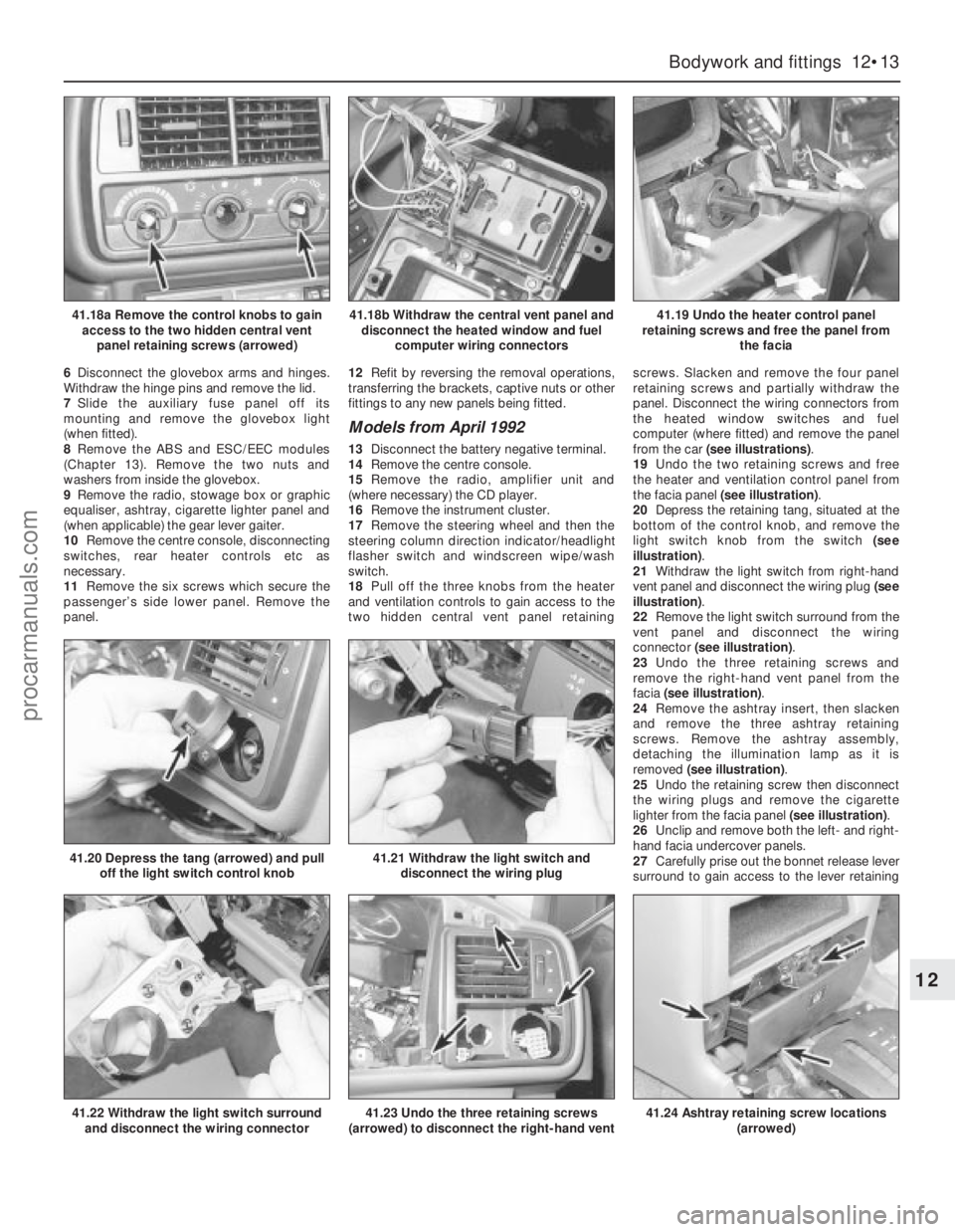
from the car (see illustrations).
19Undo the two retaining screws and free
the heater and ventilation control panel from
the facia panel (see illustration).
20Depress the retaining tang, situated at the
bottom of the control knob, and remove the
light switch knob from the switch (see
illustration).
21Withdraw the light switch from right-hand
vent panel and disconnect the wiring plug (see
illustration).
22Remove the light switch surround from the
vent panel and disconnect the wiring
connector (see illustration).
23Undo the three retaining screws and
remove the right-hand vent panel from the
facia (see illustration).
24Remove the ashtray insert, then slacken
and remove the three ashtray retaining
screws. Remove the ashtray assembly,
detaching the illumination lamp as it is
removed (see illustration).
25Undo the retaining screw then disconnect
the wiring plugs and remove the cigarette
lighter from the facia panel (see illustration).
26Unclip and remove both the left- and right-
hand facia undercover panels.
27Carefully prise out the bonnet release lever
surround to gain access to the lever retaining
Bodywork and fittings 12•13
12
41.18a Remove the control knobs to gain
access to the two hidden central vent
panel retaining screws (arrowed)41.18b Withdraw the central vent panel and
disconnect the heated window and fuel
computer wiring connectors41.19 Undo the heater control panel
retaining screws and free the panel from
the facia
41.22 Withdraw the light switch surround
and disconnect the wiring connector
41.20 Depress the tang (arrowed) and pull
off the light switch control knob41.21 Withdraw the light switch and
disconnect the wiring plug
41.23 Undo the three retaining screws
(arrowed) to disconnect the right-hand vent41.24 Ashtray retaining screw locations
(arrowed)
procarmanuals.com
Page 178 of 255
Chapter 13
Body electrical system
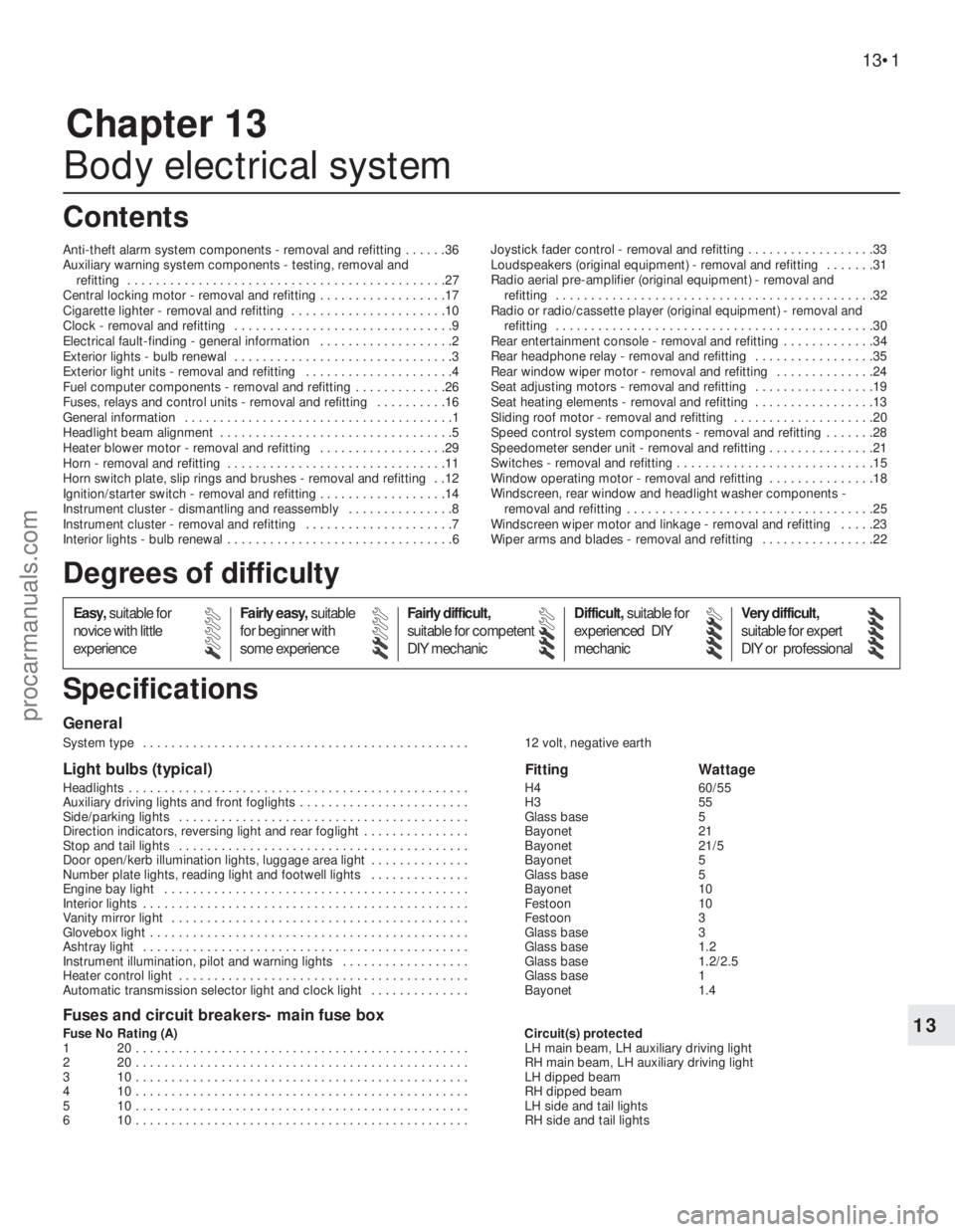
Anti-theft alarm system components - removal and refitting . . . . . .36
Auxiliary warning system components - testing, removal and
refitting . . . . . . . . . . . . . . . . . . . . . . . . . . . . . . . . . . . . . . . . . . . . .27
Central locking motor - removal and refitting . . . . . . . . . . . . . . . . . .17
Cigarette lighter - removal and refitting . . . . . . . . . . . . . . . . . . . . . .10
Clock - removal and refitting . . . . . . . . . . . . . . . . . . . . . . . . . . . . . . .9
Electrical fault-finding - general information . . . . . . . . . . . . . . . . . . .2
Exterior lights - bulb renewal . . . . . . . . . . . . . . . . . . . . . . . . . . . . . . .3
Exterior light units - removal and refitting . . . . . . . . . . . . . . . . . . . . .4
Fuel computer components - removal and refitting . . . . . . . . . . . . .26
Fuses, relays and control units - removal and refitting . . . . . . . . . .16
General information . . . . . . . . . . . . . . . . . . . . . . . . . . . . . . . . . . . . . .1
Headlight beam alignment . . . . . . . . . . . . . . . . . . . . . . . . . . . . . . . . .5
Heater blower motor - removal and refitting . . . . . . . . . . . . . . . . . .29
Horn - removal and refitting . . . . . . . . . . . . . . . . . . . . . . . . . . . . . . .11
Horn switch plate, slip rings and brushes - removal and refitting . .12
Ignition/starter switch - removal and refitting . . . . . . . . . . . . . . . . . .14
Instrument cluster - dismantling and reassembly . . . . . . . . . . . . . . .8
Instrument cluster - removal and refitting . . . . . . . . . . . . . . . . . . . . .7
Interior lights - bulb renewal . . . . . . . . . . . . . . . . . . . . . . . . . . . . . . . .6Joystick fader control - removal and refitting . . . . . . . . . . . . . . . . . .33
Loudspeakers (original equipment) - removal and refitting . . . . . . .31
Radio aerial pre-amplifier (original equipment) - removal and
refitting . . . . . . . . . . . . . . . . . . . . . . . . . . . . . . . . . . . . . . . . . . . . .32
Radio or radio/cassette player (original equipment) - removal and
refitting . . . . . . . . . . . . . . . . . . . . . . . . . . . . . . . . . . . . . . . . . . . . .30
Rear entertainment console - removal and refitting . . . . . . . . . . . . .34
Rear headphone relay - removal and refitting . . . . . . . . . . . . . . . . .35
Rear window wiper motor - removal and refitting . . . . . . . . . . . . . .24
Seat adjusting motors - removal and refitting . . . . . . . . . . . . . . . . .19
Seat heating elements - removal and refitting . . . . . . . . . . . . . . . . .13
Sliding roof motor - removal and refitting . . . . . . . . . . . . . . . . . . . .20
Speed control system components - removal and refitting . . . . . . .28
Speedometer sender unit - removal and refitting . . . . . . . . . . . . . . .21
Switches - removal and refitting . . . . . . . . . . . . . . . . . . . . . . . . . . . .15
Window operating motor - removal and refitting . . . . . . . . . . . . . . .18
Windscreen, rear window and headlight washer components -
removal and refitting . . . . . . . . . . . . . . . . . . . . . . . . . . . . . . . . . . .25
Windscreen wiper motor and linkage - removal and refitting . . . . .23
Wiper arms and blades - removal and refitting . . . . . . . . . . . . . . . .22
General
System type . . . . . . . . . . . . . . . . . . . . . . . . . . . . . . . . . . . . . . . . . . . . . . 12 volt, negative earth
Light bulbs (typical)Fitting Wattage
Headlights . . . . . . . . . . . . . . . . . . . . . . . . . . . . . . . . . . . . . . . . . . . . . . . . H4 60/55
Auxiliary driving lights and front foglights . . . . . . . . . . . . . . . . . . . . . . . . H3 55
Side/parking lights . . . . . . . . . . . . . . . . . . . . . . . . . . . . . . . . . . . . . . . . . Glass base 5
Direction indicators, reversing light and rear foglight . . . . . . . . . . . . . . . Bayonet 21
Stop and tail lights . . . . . . . . . . . . . . . . . . . . . . . . . . . . . . . . . . . . . . . . . Bayonet 21/5
Door open/kerb illumination lights, luggage area light . . . . . . . . . . . . . . Bayonet 5
Number plate lights, reading light and footwell lights . . . . . . . . . . . . . . Glass base 5
Engine bay light . . . . . . . . . . . . . . . . . . . . . . . . . . . . . . . . . . . . . . . . . . . Bayonet 10
Interior lights . . . . . . . . . . . . . . . . . . . . . . . . . . . . . . . . . . . . . . . . . . . . . . Festoon 10
Vanity mirror light . . . . . . . . . . . . . . . . . . . . . . . . . . . . . . . . . . . . . . . . . . Festoon 3
Glovebox light . . . . . . . . . . . . . . . . . . . . . . . . . . . . . . . . . . . . . . . . . . . . . Glass base 3
Ashtray light . . . . . . . . . . . . . . . . . . . . . . . . . . . . . . . . . . . . . . . . . . . . . . Glass base 1.2
Instrument illumination, pilot and warning lights . . . . . . . . . . . . . . . . . . Glass base 1.2/2.5
Heater control light . . . . . . . . . . . . . . . . . . . . . . . . . . . . . . . . . . . . . . . . . Glass base 1
Automatic transmission selector light and clock light . . . . . . . . . . . . . . Bayonet 1.4
Fuses and circuit breakers- main fuse box
Fuse No Rating (A) Circuit(s) protected
1 20 . . . . . . . . . . . . . . . . . . . . . . . . . . . . . . . . . . . . . . . . . . . . . . . LH main beam, LH auxiliary driving light
2 20 . . . . . . . . . . . . . . . . . . . . . . . . . . . . . . . . . . . . . . . . . . . . . . . RH main beam, LH auxiliary driving light
3 10 . . . . . . . . . . . . . . . . . . . . . . . . . . . . . . . . . . . . . . . . . . . . . . . LH dipped beam
4 10 . . . . . . . . . . . . . . . . . . . . . . . . . . . . . . . . . . . . . . . . . . . . . . . RH dipped beam
5 10 . . . . . . . . . . . . . . . . . . . . . . . . . . . . . . . . . . . . . . . . . . . . . . . LH side and tail lights
6 10 . . . . . . . . . . . . . . . . . . . . . . . . . . . . . . . . . . . . . . . . . . . . . . . RH side and tail lights
13•1
Easy,suitable for
novice with little
experienceFairly easy,suitable
for beginner with
some experienceFairly difficult,
suitable for competent
DIY mechanicDifficult,suitable for
experienced DIY
mechanicVery difficult,
suitable for expert
DIY or professional
Degrees of difficulty
Specifications Contents
13
procarmanuals.com
Page 197 of 255
Speed control module
Models before April 1992
9Refer to Section 27. The speed control
module shares the same mountings as the
AWS module; the AWS module is larger.
Models from April 1992
10The speed control module fitted to these
models is situated behind the glovebox on the
left-hand side of the facia. To gain access to
the module remove the left-hand facia
undercover panel. The speed control module
is vertically mounted just to the right of the
engine management module. Push the module
upwards to release the retaining clips then
lower it out from under the facia and
disconnect the wiring connector (see
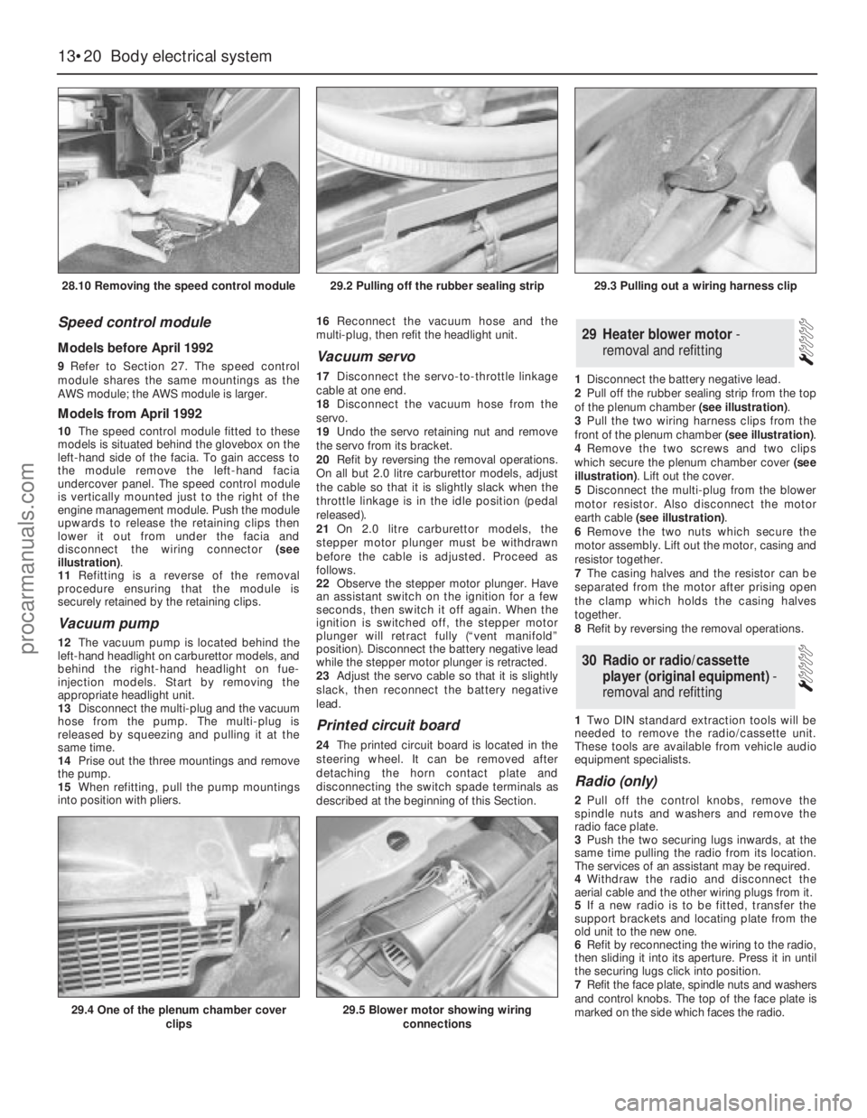
illustration).
11Refitting is a reverse of the removal
procedure ensuring that the module is
securely retained by the retaining clips.
Vacuum pump
12The vacuum pump is located behind the
left-hand headlight on carburettor models, and
behind the right-hand headlight on fue-
injection models. Start by removing the
appropriate headlight unit.
13Disconnect the multi-plug and the vacuum
hose from the pump. The multi-plug is
released by squeezing and pulling it at the
same time.
14Prise out the three mountings and remove
the pump.
15When refitting, pull the pump mountings
into position with pliers. 16Reconnect the vacuum hose and the
multi-plug, then refit the headlight unit.
Vacuum servo
17Disconnect the servo-to-throttle linkage
cable at one end.
18Disconnect the vacuum hose from the
servo.
19Undo the servo retaining nut and remove
the servo from its bracket.
20Refit by reversing the removal operations.
On all but 2.0 litre carburettor models, adjust
the cable so that it is slightly slack when the
throttle linkage is in the idle position (pedal
released).
21On 2.0 litre carburettor models, the
stepper motor plunger must be withdrawn
before the cable is adjusted. Proceed as
follows.
22Observe the stepper motor plunger. Have
an assistant switch on the ignition for a few
seconds, then switch it off again. When the
ignition is switched off, the stepper motor
plunger will retract fully (“vent manifold”
position). Disconnect the battery negative lead
while the stepper motor plunger is retracted.
23Adjust the servo cable so that it is slightly
slack, then reconnect the battery negative
lead.
Printed circuit board
24The printed circuit board is located in the
steering wheel. It can be removed after
detaching the horn contact plate and
disconnecting the switch spade terminals as
described at the beginning of this Section.1Disconnect the battery negative lead.
2Pull off the rubber sealing strip from the top
of the plenum chamber (see illustration).
3Pull the two wiring harness clips from the
front of the plenum chamber (see illustration).
4Remove the two screws and two clips
which secure the plenum chamber cover (see
illustration). Lift out the cover.
5Disconnect the multi-plug from the blower
motor resistor. Also disconnect the motor
earth cable (see illustration).
6Remove the two nuts which secure the
motor assembly. Lift out the motor, casing and
resistor together.
7The casing halves and the resistor can be
separated from the motor after prising open
the clamp which holds the casing halves
together.
8Refit by reversing the removal operations.
1Two DIN standard extraction tools will be
needed to remove the radio/cassette unit.
These tools are available from vehicle audio
equipment specialists.
Radio (only)
2Pull off the control knobs, remove the
spindle nuts and washers and remove the
radio face plate.
3Push the two securing lugs inwards, at the
same time pulling the radio from its location.
The services of an assistant may be required.
4Withdraw the radio and disconnect the
aerial cable and the other wiring plugs from it.
5If a new radio is to be fitted, transfer the
support brackets and locating plate from the
old unit to the new one.
6Refit by reconnecting the wiring to the radio,
then sliding it into its aperture. Press it in until
the securing lugs click into position.
7Refit the face plate, spindle nuts and washers
and control knobs. The top of the face plate is
marked on the side which faces the radio.
30Radio or radio/cassette
player (original equipment) -
removal and refitting
29Heater blower motor -
removal and refitting
13•20Body electrical system
28.10 Removing the speed control module
29.4 One of the plenum chamber cover
clips29.5 Blower motor showing wiring
connections
29.2 Pulling off the rubber sealing strip29.3 Pulling out a wiring harness clip
procarmanuals.com
Page 201 of 255
WD•0
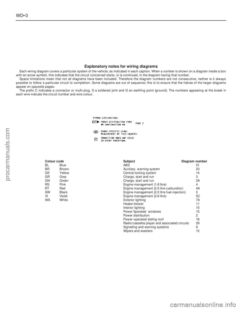
Explanatory notes for wiring diagrams
Each wiring diagram covers a particular system of the vehicle; as indicated in each caption. When a number is shown on a diagram inside a box
with an arrow symbol, this indicates that the circuit concerned starts, or is continued, in the diagram having that number.
Space limitations mean that not all diagrams have been included. Therefore the diagram numbers are not consecutive, neither is it always
possible to follow a particular circuit to completion. Some diagrams are out of sequence; this is to ensure that the halves of the larger diagrams
appear on opposite pages.
The prefix C indicates a connector or multi-plug, S a soldered joint and G an earthing point (ground). The numbers appearing at the break in
each wire indicate the circuit number and wire colour.
Colour code
BLBlue
BRBrown
GEYellow
GRGrey
GNGreen
RSPink
RT Red
SWBlack
VIViolet
WSWhiteSubjectDiagram number
ABS21
Auxiliary warning system23
Central locking system14
Charge, start and run3
Charge, start and run3A
Engine management (1.8 litre)4
Engine management (2.0 litre carburettor)4A
Engine management (2.0 litre fuel-injection)5
Engine management (2.8 litre)5C
Exterior lighting7A
Heater blower11
Interior lighting10
Power 0perated windows15
Power distribution2
Power-operated sliding roof16
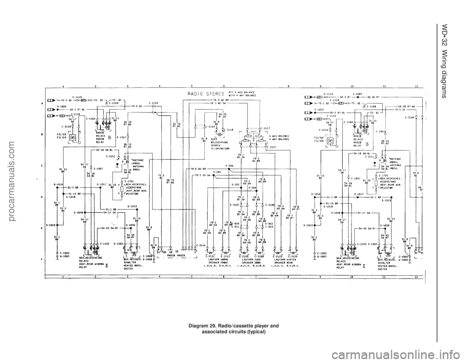
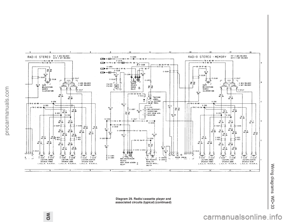
Radio/cassette player and associated circuits29
Signalling and warning systems9
Wipers and washers12
procarmanuals.com
Page 233 of 255
WD•32Wiring diagrams
Diagram 29. Radio/cassette player and
associated circuits (typical)
procarmanuals.com
Page 234 of 255
Wiring diagrams WD•33
WD
Diagram 29. Radio/cassette player and
associated circuits (typical) (continued)
procarmanuals.com
Page 254 of 255
Q
Quarter window moulding - 12•10
R
Radiator - 3•3, 12•9
Radio fader light - 13•8
Radio or radio/cassette player - 13•20, 13•21
Rear light cluster - 13•5, 13•6
Recline motor - 13•15
Regulator mechanism - 12•9
Relays - 13•13
Respraying - 12•3
Reversing light switch - 7B•3, 13•12, 13•13
Ride height control - 11•12, 11•13
Road test - 1•16
Rocker shaft - 2C•12
Rotor arm - 5•5
Routine maintenance and servicing- 1•1et
seq
Rust holes or gashes in bodywork - 12•2
S
Safety first! - 0•5
Scalding - 0•5
Scratches in bodywork - 12•2
Screw threads and fastenings - REF•4
Seals and hoses - 1•19
Seat air cushion - 12•17
Seat belts - 0•12, 1•10, 12•17, 12•18
Seats - 0•12, 12•17, 12•18, 13•10, 13•13,
13•15
Selector rod - 7B•4
Servo - 10•12, 10•13, 13•20
Shock absorbers - 0•12, 0•13, 11•12
Short-circuit - 13•4
Side mouldings - 12•10
Sidelight - 13•4
Sliding roof - 12•5, 13•12, 13•16
Spare parts - 0•8
Spark plugs - 1•12, 5•5
Speakers - 13•21, 13•22
Speed control system components - 13•19,
13•20
Speedometer sender unit - 13•16
Spoiler - 12•11
Springs - 0•13, 11•11
Starter inhibitor/reversing light switch -
7B•3, 13•13
Starter motor - 5•4, 5•5
Starter motor noisy or excessively-rough in
engagement - REF•6
Starter motor turns engine slowly - REF•6
Steering and suspension - 0•12, 0•13, 1•15,
1•16, 11•1et seq,REF•10
Steering column- 0•11, 11•5
Steering gear - 11•3
Steering intermediate shaft and flexible
coupling - 11•6Steering play - REF•10
Steering rack bellows - 11•4
Steering stiff - REF•10
Steering wheel - 0•11, 11•4, 11•5
Steering wheel and column -
Stop-light switch - 13•12
Strut - 11•9, 11•10
Stub axle carrier - 11•7
Sump - 2A•9, 2A•16, 2B•15, 2C•9, 2C•19
Switch illumination lights - 13•8
Switches - 13•9, 13•11, 13•12, 13•13,
13•18, 13•19
T
Tailgate - 12•4, 12•7, 13•12, 13•18
Tailgate wash/wipe inoperative, or
unsatisfactory in operation - REF•11
Tailgate window mouldings - 12•10
Tappets - 2C•13
Temperature gauge gives false reading -
REF•11
Temperature gauge sender - 3•7
Thermostat - 3•3
Throttle body - 4•15
Throttle cable - 4•7
Throttle kicker - 4•13
Throttle pedal - 4•6
Throttle position sensor - 4•15
Timing belt - 2A•8, 2A•14, 2A•18
Timing chain - 2B•8, 2B•10, 2C•9, 2C•17
Tools and working facilities- REF•1et seq
Towing - 0•7
Track rod end - 11•6
Transmission fluid brown, or has burned
smell - REF•9
Transmission slips, shifts roughly, is noisy,
or has no drive in forward or reverse
gears - REF•9
Transmission will not downshift (kickdown)
with accelerator pedal fully depressed -
REF•9
Tyre wear - REF•10
Tyres - 0•14, 1•7
U
Ultrasonic sensor - 13•23
Underbody inspection - 1•15
Unleaded fuel - 4•23
V
Vacuum dump valve/switch - 13•19
Vacuum hoses - 2C•7
Vacuum line modification - 7B•4
Vacuum pull-down adjustment - 4•13
Vacuum pump - 13•20
Vacuum servo - 10•12, 10•13, 13•20
Valve block and pump assembly - 10•13
Valve clearances - 1•13, 2A•20, 2C•21Valve grinding - 2A•14
Vane airflow meter(s) - 4•16
Vanity mirror light - 13•7
Vapour separator - 4•7
Vehicle identification - 0•9, 0•12
Vehicle pulls to one side - REF•9, REF•10
Vehicle speed sensor - 5•12
Vibration damper (MT75type gearbox) - 8•4
Viscous-coupled fan - 3•5
W
Wandering or general instability - REF•10
Warning light bulbs - 13•18
Wash/wipe inoperative, or unsatisfactory in
operation - REF•11
Wash/wipe switch - 13•12
Washer fluid - 1•7, 13•19
Washer jets inoperative - REF•11
Washer pump fails to operate - REF•11
Washer pump runs for some time before
fluid is emitted from jets - REF•11
Water pump - 3•5
Water pump/alternator drivebelt - 3•7
Weatherstrip - 12•7
Weber 2V carburettor - 4•9, 4•10
Weber 2V TLD carburettor - 4•11, 4•12,
4•13
Wheel alignment - 11•7
Wheel bearings - 0•13, 11•8, 11•11
Wheel changing - 0•7
Wheel sensors - 10•12
Wheel stud - 11•11
Wheel wobble and vibration - REF•10
Wheels - 0•14, 1•10
Wheels locking under normal braking -
REF•10
Window frame mouldings - 12•10
Window glass - 12•8
Window glass fails to move - REF•11
Window glass slow to move - REF•11
Window glass will only move in one
direction - REF•11
Window operating motor - 13•15
Window operating switch - 13•12
Windscreen - 0•11, 12•9
Windscreen mouldings - 12•10
Windscreen, rear window and headlight
washer components - 13•17
Wiper arms and blades - 13•16
Wiper blades - 1•9
Wiper blades fail to clean the glass
effectively - REF•11
Wiper blades sweep over too large or too
small an area of the glass - REF•11
Wiper motor - 13•17
Wipers fail to operate, or operate very
slowly - REF•11
Wiring diagrams- WD•0 et seq
Working facilities - REF•3
IND•3Index
procarmanuals.com