1985 FORD GRANADA jump start terminals
[x] Cancel search: jump start terminalsPage 14 of 255

DOHC engines
12On this engine, the coolant/alternator
drivebelt also drives the power steering pump
and (where applicable) the air conditioning
compressor. The drivebelt tension is set by an
automatic tensioner assembly.
13The condition of the drivebelt should be
checked as described above.
14An idea of the amount of wear which has
taken place on the belt can be gained from the
position of indicator mark (A) on the mounting
bracket in relation to the block (B) on the
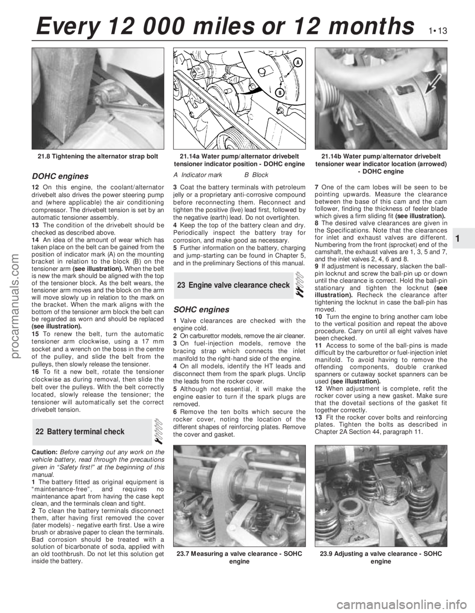
tensioner arm (see illustration).When the belt
is new the mark should be aligned with the top
of the tensioner block. As the belt wears, the
tensioner arm moves and the block on the arm
will move slowly up in relation to the mark on
the bracket. When the mark aligns with the
bottom of the tensioner arm block the belt can
be regarded as worn and should be replaced
(see illustration).
15To renew the belt, turn the automatic
tensioner arm clockwise, using a 17 mm
socket and a wrench on the boss in the centre
of the pulley, and slide the belt from the
pulleys, then slowly release the tensioner.
16To fit a new belt, rotate the tensioner
clockwise as during removal, then slide the
belt over the pulleys. With the belt correctly
located, slowly release the tensioner; the
tensioner will automatically set the correct
drivebelt tension.
Caution:Before carrying out any work on the
vehicle battery, read through the precautions
given in “Safety first!” at the beginning of this
manual.
1The battery fitted as original equipment is
“maintenance-free”, and requires no
maintenance apart from having the case kept
clean, and the terminals clean and tight.
2To clean the battery terminals disconnect
them, after having first removed the cover
(later models) -negative earth first. Use a wire
brush or abrasive paper to clean the terminals.
Bad corrosion should be treated with a
solution of bicarbonate of soda, applied with
an old toothbrush. Do not let this solution get
inside the battery.3Coat the battery terminals with petroleum
jelly or a proprietary anti-corrosive compound
before reconnecting them. Reconnect and
tighten the positive (live) lead first, followed by
the negative (earth) lead. Do not overtighten.
4Keep the top of the battery clean and dry.
Periodically inspect the battery tray for
corrosion, and make good as necessary.
5Further information on the battery, charging
and jump-starting can be found in Chapter 5,
and in the preliminary Sections of this manual.
SOHC engines
1Valve clearances are checked with the
engine cold.
2On carburettor models, remove the air cleaner.
3On fuel-injection models, remove the
bracing strap which connects the inlet
manifold to the right-hand side of the engine.
4On all models, identify the HT leads and
disconnect them from the spark plugs. Unclip
the leads from the rocker cover.
5Although not essential, it will make the
engine easier to turn if the spark plugs are
removed.
6Remove the ten bolts which secure the
rocker cover, noting the location of the
different shapes of reinforcing plates. Remove
the cover and gasket.7One of the cam lobes will be seen to be
pointing upwards. Measure the clearance
between the base of this cam and the cam
follower, finding the thickness of feeler blade
which gives a firm sliding fit(see illustration).
8The desired valve clearances are given in
the Specifications. Note that the clearances
for inlet and exhaust valves are different.
Numbering from the front (sprocket) end of the
camshaft, the exhaust valves are 1, 3, 5 and 7,
and the inlet valves 2, 4, 6 and 8.
9If adjustment is necessary, slacken the ball-
pin locknut and screw the ball-pin up or down
until the clearance is correct. Hold the ball-pin
stationary and tighten the locknut(see
illustration).Recheck the clearance after
tightening the locknut in case the ball-pin has
moved.
10Turn the engine to bring another cam lobe
to the vertical position and repeat the above
procedure. Carry on until all eight valves have
been checked.
11Access to some of the ball-pins is made
difficult by the carburettor or fuel-injection inlet
manifold. To avoid having to remove the
offending components, double cranked
spanners or cutaway socket spanners can be
used (see illustration).
12When adjustment is complete, refit the
rocker cover using a new gasket. Make sure
that the dovetail sections of the gasket fit
together correctly.
13Fit the rocker cover bolts and reinforcing
plates. Tighten the bolts as described in
Chapter 2A Section 44, paragraph 11.
23Engine valve clearance check
22Battery terminal check
1•13
1
Every 12 000 miles or 12 months
21.14a Water pump/alternator drivebelt
tensioner indicator position - DOHC engine
A Indicator markB Block
21.14b Water pump/alternator drivebelt
tensioner wear indicator location (arrowed)
- DOHC engine21.8 Tightening the alternator strap bolt
23.7 Measuring a valve clearance - SOHC
engine23.9 Adjusting a valve clearance - SOHC
engine
procarmanuals.com
Page 120 of 255

engine coolant temperature sensor. The
crankshaft speed/position sensor is activated
by a toothed disc on the rear of the crankshaft,
inside the cylinder block. The disc has 35
equally spaced teeth (one every 10°), with a
gap in the 36th position. The gap is used by
the sensor to determine the crankshaft
position relative to Top Dead Centre (TDC) of
No 1 piston.
The ignition advance is a function of the
ESC II module, and is controlled by vacuum.
The module is connected to the carburettor by
a vacuum pipe, and a transducer in the
module translates the vacuum signal into an
electrical voltage. From the vacuum signal, the
module determines engine load; engine speed
and temperature are determined from the
crankshaft speed/position sensor and the
engine coolant temperature sensor. The
module has a range of spark advance settings
stored in the memory, and a suitable setting is
selected for the relevant engine speed, load
and temperature. The degree of advance can
thus be constantly varied to suit the prevailing
engine speed and load conditions.
On DOHC fuel-injected engines, a
development of the EEC IV (Electronic Engine
Control IV) engine management system is
used to control both the ignition and fuel-
injection systems. The EEC IV module receives
information from a crankshaft speed/position
sensor (the same as that fitted to the
carburettor models), a throttle position sensor,
an engine coolant temperature sensor, a fuel
temperature sensor, an air charge temperature
sensor, a Manifold Absolute Pressure (MAP)
sensor, and a vehicle speed sensor (mounted
on the gearbox). Additionally, on models with
a catalytic converter, an additional input is
supplied to the EEC IV module from an
exhaust gas oxygen (HEGO) sensor. On
models with automatic transmission,
additional sensors are fitted to the
transmission to inform the EEC IV module
when the transmission is in neutral, and when
the downshift is being operated.
The module provides outputs to control the
fuel pump, fuel-injectors, idle speed, ignition
system and automatic transmission .
Additionally, on models with air conditioning,
the EEC IV module disengages the air
conditioning compressor clutch when starting
the engine or when the engine is suddenly
accelerated. On models fitted with a catalytic
converter, the EEC IV module also controls the
carbon canister purge solenoid valve.
Using the inputs from the various sensors,
the EEC IV module computes the optimum
ignition advance, and fuel-injector pulse
duration to suit the prevailing engine
conditions.
On 2.4 & 2.9 litre V6 engines, the system
operates in much the same way as that fitted
to the DOHC fuel-injected engine, noting the
following points.
a)There is no crankshaft speed/position
sensor.
b)The vehicle speed sensor is only fitted to
models equipped with a catalytic
converter.Precautions
ESC II module
Although it will tolerate all normal under-
bonnet conditions, the ESC II module may be
adversely affected by water entry during
steam cleaning or pressure washing of the
engine bay.
If cleaning the engine bay, therefore, take
care not to direct jets of water or steam at the
ESC II module. If this cannot be avoided,
remove the module completely, and protect its
multi-plug with a plastic bag.
Ignition system HT voltage
Take care to avoid receiving electric shocks
from the HT side of the ignition system. Do not
handle HT leads, or touch the distributor or
coil, when the engine is running. When tracing
faults in the HT system, use well insulated
tools to manipulate live leads. Electronic
ignition HT voltage could prove fatal.
Electronic ignition systems
General
Further details of the various systems are
given in the relevant Sections of this Chapter.
While some repair procedures are given, the
usual course of action is to renew the
component concerned. The owner whose
interest extends beyond mere component
renewal should obtain a copy of the
Automobile Electrical & Electronic Systems
Manual, available from the publishers of this
manual.
It is necessary to take extra care when
working on the electrical system, to avoid
damage to semi-conductor devices (diodes
and transistors), and to avoid the risk of
personal injury. In addition to the precautions
given in Safety first!at the beginning of this
manual, observe the following when working
on the system:
Always remove rings, watches, etc before
working on the electrical system.Even with the
battery disconnected, capacitive discharge
could occur if a component’s live terminal is
earthed through a metal object. This could
cause a shock or nasty burn.
Do not reverse the battery connections.
Components such as the alternator, electronic
control units, or any other components having
semi-conductor circuitry, could be irreparably
damaged.
If the engine is being started using jump
leads and a slave battery, connect thebatteries positive-to-positiveand negative-to-
negative(see “Jump starting”). This also
applies when connecting a battery charger.
Never disconnect the battery terminals, the
alternator, any electrical wiring, or any test
instruments, when the engine is running.
Do not allow the engine to turn the alternator
when the alternator is not connected.
Never test for alternator output by “flashing”
the output lead to earth.
Never use an ohmmeter of the type
incorporating a hand-cranked generator for
circuit or continuity testing.
Always ensure that the battery negative lead
is disconnected when working on the
electrical system.
Before using electric-arc welding equipment
on the car, disconnect the battery, alternator,
and components such as the fuel-
injection/ignition electronic control unit, to
protect them from the risk of damage.
Refer to Chapter 13
1In normal use the battery should not require
charging from an external source, unless the
vehicle is laid up for long periods, when it
should be recharged every six weeks or so. If
vehicle use consists entirely of short runs in
darkness it is also possible for the battery to
become discharged. Otherwise, a regular
need for recharging points to a fault in the
battery or elsewhere in the charging system.
2There is no need to disconnect the battery
from the vehicle wiring when using a battery
charger, but switch off the ignition and leave
the bonnet open.
3Domestic battery chargers (up to about 6
amps output) may safely be used overnight
without special precautions. Make sure that
the charger is set to deliver 12 volts before
connecting it. Connect the leads (red or
positive to the positive terminal, black or
negative to the negative terminal) before
switching the charger on at the mains.
4When charging is complete, switch off at
the mains beforedisconnecting the charger
from the battery. Remember that the battery
will be giving off hydrogen gas, which is
potentially explosive.
5Charging at a higher rate should only be
carried out under carefully controlled
conditions. Very rapid or “boost” charging
should be avoided if possible, as it is liable to
cause permanent damage to the battery
through overheating.
6During any sort of charging, battery
electrolyte temperature should never exceed
38°C (100°F). If the battery becomes hot, or
the electrolyte is effervescing vigorously,
charging should be stopped.
3Battery - charging
2Electrical fault-finding - general
information
Engine electrical systems 5•3
5
Warning. The voltages produced
by the electronic ignition system
are considerably higher than those
produced by conventional
systems. Extreme care must be taken when
working on the system with the ignition
switched on. Persons with surgically-
implanted cardiac pacemaker devices
should keep well clear of the ignition
circuits, components and test equipment.
procarmanuals.com
Page 241 of 255

REF•6
Engine fails to rotate when attempting to start
m mBattery terminal connections loose or corroded (Chapter 1).
m mBattery discharged or faulty (Chapter 5).
m mBroken, loose or disconnected wiring in the starting circuit
(Chapter 5).
m mDefective starter solenoid or switch (Chapter 5).
m mDefective starter motor (Chapter 5).
m mStarter pinion or flywheel/driveplate ring gear teeth loose or broken
(Chapters 2 or 5).
m mEngine earth strap broken or disconnected.
Starter motor turns engine slowly
m
mPartially-discharged battery (recharge, use jump leads, or push
start) (Chapter 5).
m mBattery terminals loose or corroded (Chapter 1).
m mBattery earth to body defective (Chapter 5).
m mEngine earth strap loose.
m mStarter motor (or solenoid) wiring loose (Chapter 5).
m mStarter motor internal fault (Chapter 5).
Engine rotates, but will not start
m
mFuel pump inertia switch tripped (electric pump) (Chapter 4).
m mFuel tank empty.
m mBattery discharged (engine rotates slowly) (Chapter 5).
m mBattery terminal connections loose or corroded (Chapter 1).
m mIgnition components damp or damaged (Chapters 1 and 5).
m mBroken, loose or disconnected wiring in the ignition circuit
(Chapters 1 and 5).
m mWorn, faulty or incorrectly-gapped spark plugs (Chapter 1).
m mFuel injection system fault (Chapter 4).
m mMajor mechanical failure (eg broken timing chain) (Chapter 2).
Engine difficult to start when cold
m
mBattery discharged (Chapter 5).
m mBattery terminal connections loose or corroded (Chapter 1).
m mWorn, faulty or incorrectly-gapped spark plugs (Chapter 1).
m mFuel injection system fault (Chapter 4).
m mOther ignition system fault (Chapters 1 and 5).
m mLow cylinder compressions (Chapter 2).
Engine difficult to start when hot
m
mAir filter element dirty or clogged (Chapter 1).
m mFuel injection system fault (Chapter 4).
m mLow cylinder compressions (Chapter 2).
Starter motor noisy or excessively-rough in
engagement
m mStarter pinion or flywheel/driveplate ring gear teeth loose or broken
(Chapters 2 or 5).
m mStarter motor mounting bolts loose or missing (Chapter 5).
m mStarter motor internal components worn or damaged (Chapter 5).
Engine starts, but stops immediately
m
mLoose or faulty electrical connections in the ignition circuit
(Chapters 1 and 5).
m mVacuum leak at the throttle body or inlet manifold (Chapter 4).
m mFuel injection system fault (Chapter 4).
Engine idles erratically
m
mCarburettor stepper motor plunger dirty (2.0 litre only) (Chapter 5)
m mIncorrectly-adjusted idle speed (Chapter 4).
m mAir filter element clogged (Chapter 1).
m mVacuum leak at the throttle body, inlet manifold or associated hoses
(Chapter 4).
m mWorn, faulty or incorrectly-gapped spark plugs (Chapter 1).
m mUneven or low cylinder compressions (Chapter 2).
m mCamshaft lobes worn (Chapter 2).
m mFuel injection system fault (Chapter 4).
Engine misfires at idle speed
m
mWorn, faulty or incorrectly-gapped spark plugs (Chapter 1).
m mFaulty spark plug HT leads (Chapter 5).
m mVacuum leak at the throttle body, inlet manifold or associated hoses
(Chapter 4).
m mFuel injection system fault (Chapter 4).
m mDistributor cap cracked or tracking internally, where applicable
(Chapter 5).
m mUneven or low cylinder compressions (Chapter 2).
m mDisconnected, leaking, or perished crankcase ventilation hoses
(Chapter 4).
Fault Finding
spark plugs may only be pointers to some underlying fault.
The pages which follow provide an easy-reference guide to the more
common problems which may occur during the operation of the
vehicle. These problems and their possible causes are grouped under
headings denoting various components or systems, such as Engine,
Cooling system, etc. The Chapter and/or Section which deals with the
problem is also shown in brackets. Whatever the fault, certain basic
principles apply. These are as follows:
Verify the fault. This is simply a matter of being sure that you know
what the symptoms are before starting work. This is particularly
important if you are investigating a fault for someone else, who may
not have described it very accurately.
Don’t overlook the obvious. For example, if the vehicle won’t start, is
there fuel in the tank? (Don’t take anyone else’s word on this particular
point, and don’t trust the fuel gauge either!) If an electrical fault isindicated, look for loose or broken wires before digging out the test
gear.
Cure the disease, not the symptom. Substituting a flat battery with a
fully-charged one will get you off the hard shoulder, but if the
underlying cause is not attended to, the new battery will go the same
way. Similarly, changing oil-fouled spark plugs for a new set will get
you moving again, but remember that the reason for the fouling (if it
wasn’t simply an incorrect grade of plug) will have to be established
and corrected.
Don’t take anything for granted. Particularly, don’t forget that a
“new” component may itself be defective (especially if it’s been rattling
around in the boot for months), and don’t leave components out of a
fault diagnosis sequence just because they are new or recently-fitted.
When you do finally diagnose a difficult fault, you’ll probably realise
that all the evidence was there from the start.
1 Engine
procarmanuals.com