1985 FORD GRANADA power steering fluid
[x] Cancel search: power steering fluidPage 2 of 255
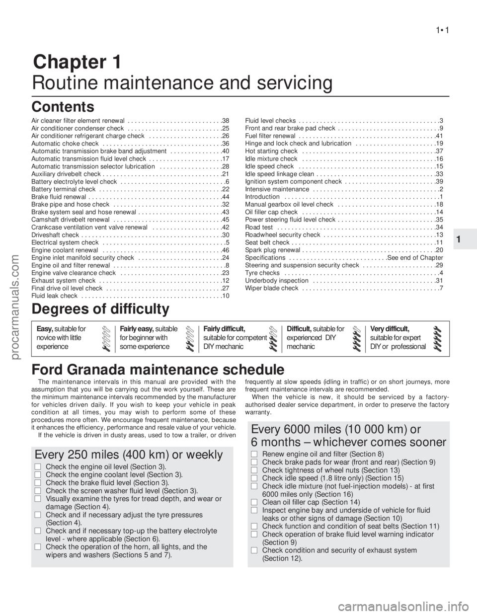
Chapter 1
Routine maintenance and servicing
Air cleaner filter element renewal . . . . . . . . . . . . . . . . . . . . . . . . . . .38
Air conditioner condenser check . . . . . . . . . . . . . . . . . . . . . . . . . . .25
Air conditioner refrigerant charge check . . . . . . . . . . . . . . . . . . . . .26
Automatic choke check . . . . . . . . . . . . . . . . . . . . . . . . . . . . . . . . . .36
Automatic transmission brake band adjustment . . . . . . . . . . . . . . .40
Automatic transmission fluid level check . . . . . . . . . . . . . . . . . . . . .17
Automatic transmission selector lubrication . . . . . . . . . . . . . . . . . .28
Auxiliary drivebelt check . . . . . . . . . . . . . . . . . . . . . . . . . . . . . . . . . .21
Battery electrolyte level check . . . . . . . . . . . . . . . . . . . . . . . . . . . . . .6
Battery terminal check . . . . . . . . . . . . . . . . . . . . . . . . . . . . . . . . . . .22
Brake fluid renewal . . . . . . . . . . . . . . . . . . . . . . . . . . . . . . . . . . . . . .44
Brake pipe and hose check . . . . . . . . . . . . . . . . . . . . . . . . . . . . . . .32
Brake system seal and hose renewal . . . . . . . . . . . . . . . . . . . . . . . .43
Camshaft drivebelt renewal . . . . . . . . . . . . . . . . . . . . . . . . . . . . . . .45
Crankcase ventilation vent valve renewal . . . . . . . . . . . . . . . . . . . .42
Driveshaft check . . . . . . . . . . . . . . . . . . . . . . . . . . . . . . . . . . . . . . . .30
Electrical system check . . . . . . . . . . . . . . . . . . . . . . . . . . . . . . . . . . .5
Engine coolant renewal . . . . . . . . . . . . . . . . . . . . . . . . . . . . . . . . . .46
Engine inlet manifold security check . . . . . . . . . . . . . . . . . . . . . . . .24
Engine oil and filter renewal . . . . . . . . . . . . . . . . . . . . . . . . . . . . . . . .8
Engine valve clearance check . . . . . . . . . . . . . . . . . . . . . . . . . . . . .23
Exhaust system check . . . . . . . . . . . . . . . . . . . . . . . . . . . . . . . . . . .12
Final drive oil level check . . . . . . . . . . . . . . . . . . . . . . . . . . . . . . . . .27
Fluid leak check . . . . . . . . . . . . . . . . . . . . . . . . . . . . . . . . . . . . . . . .10Fluid level checks . . . . . . . . . . . . . . . . . . . . . . . . . . . . . . . . . . . . . . . .3
Front and rear brake pad check . . . . . . . . . . . . . . . . . . . . . . . . . . . . .9
Fuel filter renewal . . . . . . . . . . . . . . . . . . . . . . . . . . . . . . . . . . . . . . .41
Hinge and lock check and lubrication . . . . . . . . . . . . . . . . . . . . . . .19
Hot starting check . . . . . . . . . . . . . . . . . . . . . . . . . . . . . . . . . . . . . .37
Idle mixture check . . . . . . . . . . . . . . . . . . . . . . . . . . . . . . . . . . . . . .16
Idle speed check . . . . . . . . . . . . . . . . . . . . . . . . . . . . . . . . . . . . . . .15
Idle speed linkage clean . . . . . . . . . . . . . . . . . . . . . . . . . . . . . . . . . .33
Ignition system component check . . . . . . . . . . . . . . . . . . . . . . . . . .39
Intensive maintenance . . . . . . . . . . . . . . . . . . . . . . . . . . . . . . . . . . . .2
Introduction . . . . . . . . . . . . . . . . . . . . . . . . . . . . . . . . . . . . . . . . . . . .1
Manual gearbox oil level check . . . . . . . . . . . . . . . . . . . . . . . . . . . .18
Oil filler cap check . . . . . . . . . . . . . . . . . . . . . . . . . . . . . . . . . . . . . .14
Power steering fluid level check . . . . . . . . . . . . . . . . . . . . . . . . . . . .35
Road test . . . . . . . . . . . . . . . . . . . . . . . . . . . . . . . . . . . . . . . . . . . . .34
Roadwheel security check . . . . . . . . . . . . . . . . . . . . . . . . . . . . . . . .13
Seat belt check . . . . . . . . . . . . . . . . . . . . . . . . . . . . . . . . . . . . . . . . .11
Spark plug renewal . . . . . . . . . . . . . . . . . . . . . . . . . . . . . . . . . . . . . .20
Specifications . . . . . . . . . . . . . . . . . . . . . . . . . . . .See end of Chapter
Steering and suspension security check . . . . . . . . . . . . . . . . . . . . .29
Tyre checks . . . . . . . . . . . . . . . . . . . . . . . . . . . . . . . . . . . . . . . . . . . .4
Underbody inspection . . . . . . . . . . . . . . . . . . . . . . . . . . . . . . . . . . .31
Wiper blade check . . . . . . . . . . . . . . . . . . . . . . . . . . . . . . . . . . . . . . .7
The maintenance intervals in this manual are provided with the
assumption that you will be carrying out the work yourself. These are
the minimum maintenance intervals recommended by the manufacturer
for vehicles driven daily. If you wish to keep your vehicle in peak
condition at all times, you may wish to perform some of these
procedures more often. We encourage frequent maintenance, because
it enhances the efficiency, performance and resale value of your vehicle.
If the vehicle is driven in dusty areas, used to tow a trailer, or drivenfrequently at slow speeds (idling in traffic) or on short journeys, more
frequent maintenance intervals are recommended.
When the vehicle is new, it should be serviced by a factory-
authorised dealer service department, in order to preserve the factory
warranty.
1•1
Easy,suitable for
novice with little
experienceFairly easy,suitable
for beginner with
some experienceFairly difficult,
suitable for competent
DIY mechanicDifficult,suitable for
experienced DIY
mechanicVery difficult,
suitable for expert
DIY or professional
Degrees of difficulty Contents
1
Every 250 miles (400 km) or weekly
m mCheck the engine oil level (Section 3).
m mCheck the engine coolant level (Section 3).
m mCheck the brake fluid level (Section 3).
m mCheck the screen washer fluid level (Section 3).
m mVisually examine the tyres for tread depth, and wear or
damage (Section 4).
m mCheck and if necessary adjust the tyre pressures
(Section 4).
m mCheck and if necessary top-up the battery electrolyte
level - where applicable (Section 6).
m mCheck the operation of the horn, all lights, and the
wipers and washers (Sections 5 and 7).
Every 6000 miles (10 000 km) or
6 months – whichever comes sooner
m mRenew engine oil and filter (Section 8)
m mCheck brake pads for wear (front and rear) (Section 9)
m mCheck tightness of wheel nuts (Section 13)
m mCheck idle speed (1.8 litre only) (Section 15)
m mCheck idle mixture (not fuel-injection models) - at first
6000 miles only (Section 16)
m mClean oil filler cap (Section 14)
m mInspect engine bay and underside of vehicle for fluid
leaks or other signs of damage (Section 10)
m mCheck function and condition of seat belts (Section 11)
m mCheck operation of brake fluid level warning indicator
(Section 9)
m mCheck condition and security of exhaust system
(Section 12).
Ford Granada maintenance schedule
procarmanuals.com
Page 3 of 255
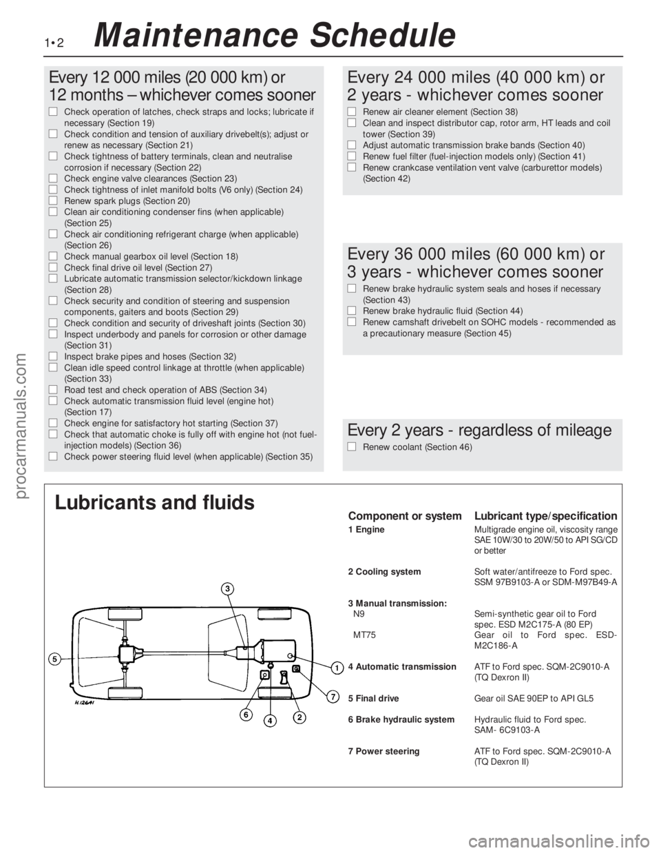
1•2
Every 12 000 miles (20 000 km) or
12 months – whichever comes sooner
m mCheck operation of latches, check straps and locks; lubricate if
necessary (Section 19)
m mCheck condition and tension of auxiliary drivebelt(s); adjust or
renew as necessary (Section 21)
m mCheck tightness of battery terminals, clean and neutralise
corrosion if necessary (Section 22)
m mCheck engine valve clearances (Section 23) m
mCheck tightness of inlet manifold bolts (V6 only) (Section 24) m
mRenew spark plugs (Section 20) m
mClean air conditioning condenser fins (when applicable)
(Section 25)
m mCheck air conditioning refrigerant charge (when applicable)
(Section 26)
m mCheck manual gearbox oil level (Section 18) m
mCheck final drive oil level (Section 27) m
mLubricate automatic transmission selector/kickdown linkage
(Section 28)
m mCheck security and condition of steering and suspension
components, gaiters and boots (Section 29)
m mCheck condition and security of driveshaft joints (Section 30) m
mInspect underbody and panels for corrosion or other damage
(Section 31)
m mInspect brake pipes and hoses (Section 32) m
mClean idle speed control linkage at throttle (when applicable)
(Section 33)
m mRoad test and check operation of ABS (Section 34)m
mCheck automatic transmission fluid level (engine hot)
(Section 17)
m mCheck engine for satisfactory hot starting (Section 37)m
mCheck that automatic choke is fully off with engine hot (not fuel-
injection models) (Section 36)
m mCheck power steering fluid level (when applicable) (Section 35)
Every 24 000 miles (40 000 km) or
2 years - whichever comes sooner
m
mRenew air cleaner element (Section 38) m
mClean and inspect distributor cap, rotor arm, HT leads and coil
tower (Section 39)
m mAdjust automatic transmission brake bands (Section 40)m
mRenew fuel filter (fuel-injection models only) (Section 41) m
mRenew crankcase ventilation vent valve (carburettor models)
(Section 42)
Every 36 000 miles (60 000 km) or
3 years - whichever comes sooner
m
mRenew brake hydraulic system seals and hoses if necessary
(Section 43)
m mRenew brake hydraulic fluid (Section 44) m
mRenew camshaft drivebelt on SOHC models - recommended as
a precautionary measure (Section 45)
Every 2 years - regardless of mileage
m
mRenew coolant (Section 46)
Lubricants and fluidsComponent or systemLubricant type/specification
1 EngineMultigrade engine oil, viscosity range
SAE 10W/30 to 20W/50 to API SG/CD
or better
2 Cooling systemSoft water/antifreeze to Ford spec.
SSM 97B9103-A or SDM-M97B49-A
3 Manual transmission:
N9Semi-synthetic gear oil to Ford
spec. ESD M2C175-A (80 EP)
MT75Gear oil to Ford spec. ESD-
M2C186-A
4 Automatic transmissionATF to Ford spec. SQM-2C9010-A
(TQ Dexron II)
5 Final driveGear oil SAE 90EP to APIGL5
6 Brake hydraulic systemHydraulic fluid to Ford spec.
SAM- 6C9103-A
7 Power steeringATFto Ford spec. SQM-2C9010-A
(TQDexron II)
Maintenance Schedule
procarmanuals.com
Page 4 of 255
1•3
1
Maintenance Schedule
Engine oil
SOHC:
With filter . . . . . . . . . . . . . . . . . . . . . . . . . . . . . .3.75 litres (6.6 pints)
DOHC:
With filter . . . . . . . . . . . . . . . . . . . . . . . . . . . . . . .4.5 litres (7.9 pints)
Without filter . . . . . . . . . . . . . . . . . . . . . . . . . . . . .4.0 litres (7.0 pints)
V6:
With filter . . . . . . . . . . . . . . . . . . . . . . . . . . . . . .4.25 litres (7.5 pints)
Cooling system
OHC . . . . . . . . . . . . . . . . . . . . . . . . . . . . . . . . . . . .8.0 litres (14.1 pints)
V6 . . . . . . . . . . . . . . . . . . . . . . . . . . . . . . . . . . . .8.5 litres (15.0 pints)
Fuel tank
All models . . . . . . . . . . . . . . . . . . . . . . . . . . . . .70 litres (15.4 gallons)
Manual gearbox
All models . . . . . . . . . . . . . . . . . . . . . . . . . . . . . .1.25 litres (2.2 pints)
Automatic transmission
All models (from dry) . . . . . . . . . . . . . . . . . . . . . . .8.5 litres (15.0 pints)
Final drive
7 inch crownwheel . . . . . . . . . . . . . . . . . . . . . . . . . .0.9 litres (1.6 pints)
7.5 inch crownwheel . . . . . . . . . . . . . . . . . . . . . . . . .1.3 litres (2.3 pints)
Power steering
OHC . . . . . . . . . . . . . . . . . . . . . . . . . . . . . . . . . . . .0.65 litres (1.1 pints)
V6 . . . . . . . . . . . . . . . . . . . . . . . . . . . . . . . . . . . .0.75 litres (1.3 pints)
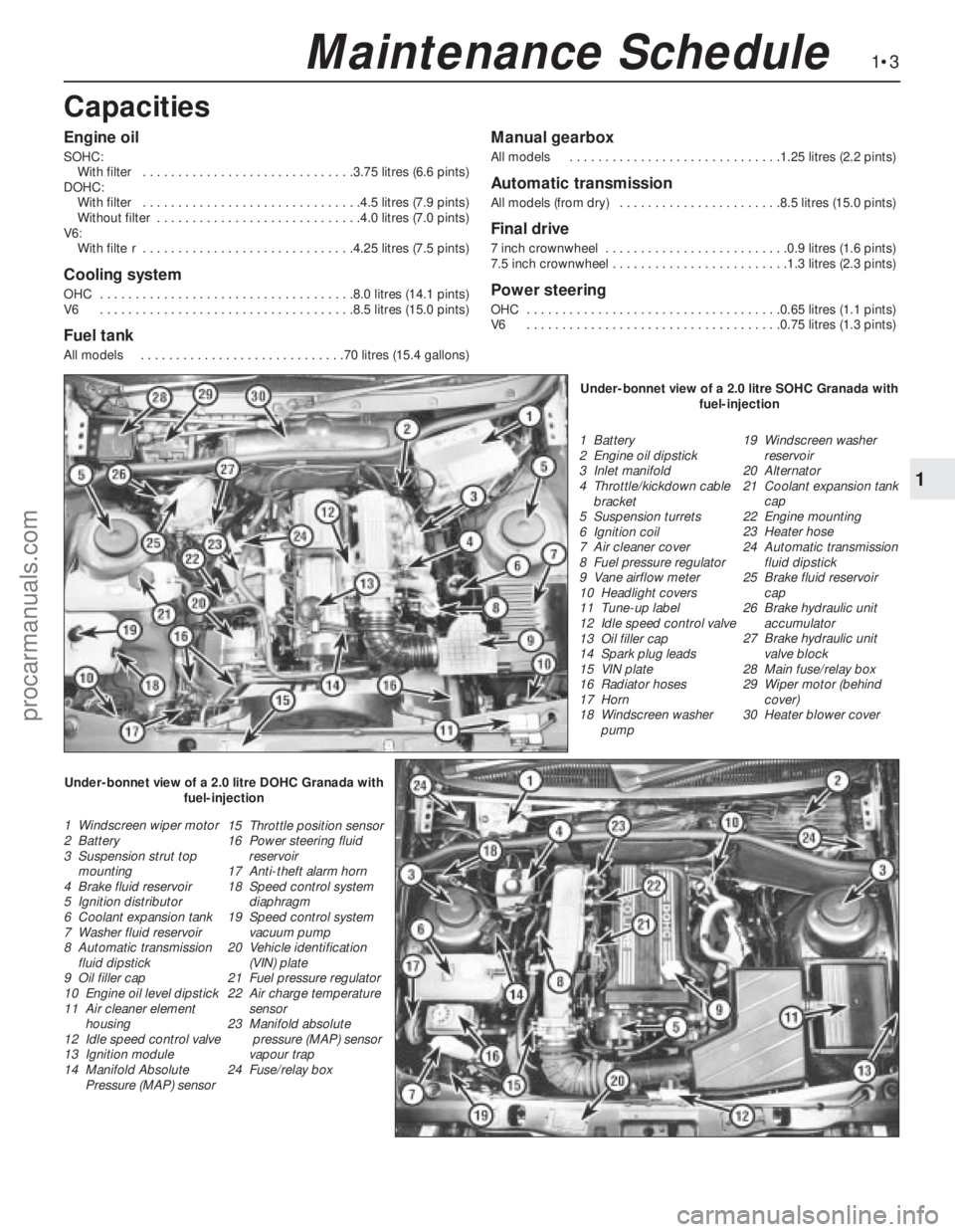
Capacities
1 Battery
2 Engine oil dipstick
3 Inlet manifold
4 Throttle/kickdown cable
bracket
5 Suspension turrets
6 Ignition coil
7 Air cleaner cover
8 Fuel pressure regulator
9 Vane airflow meter
10 Headlight covers
11 Tune-up label
12 Idle speed control valve
13 Oil filler cap
14 Spark plug leads
15 VIN plate
16 Radiator hoses
17 Horn
18 Windscreen washer
pump19 Windscreen washer
reservoir
20 Alternator
21 Coolant expansion tank
cap
22 Engine mounting
23 Heater hose
24 Automatic transmission
fluid dipstick
25 Brake fluid reservoir
cap
26 Brake hydraulic unit
accumulator
27 Brake hydraulic unit
valve block
28 Main fuse/relay box
29 Wiper motor (behind
cover)
30 Heater blower cover
1 Windscreen wiper motor
2 Battery
3 Suspension strut top
mounting
4 Brake fluid reservoir
5 Ignition distributor
6 Coolant expansion tank
7 Washer fluid reservoir
8 Automatic transmission
fluid dipstick
9 Oil filler cap
10 Engine oil level dipstick
11 Air cleaner element
housing
12 Idle speed control valve
13 Ignition module
14 Manifold Absolute
Pressure (MAP) sensor15 Throttle position sensor
16 Power steering fluid
reservoir
17 Anti-theft alarm horn
18 Speed control system
diaphragm
19 Speed control system
vacuum pump
20 Vehicle identification
(VIN) plate
21 Fuel pressure regulator
22 Air charge temperature
sensor
23 Manifold absolute
pressure (MAP) sensor
vapour trap
24 Fuse/relay boxUnder-bonnet view of a 2.0 litre SOHC Granada with
fuel-injection
Under-bonnet view of a 2.0 litre DOHC Granada with
fuel-injection
procarmanuals.com
Page 5 of 255
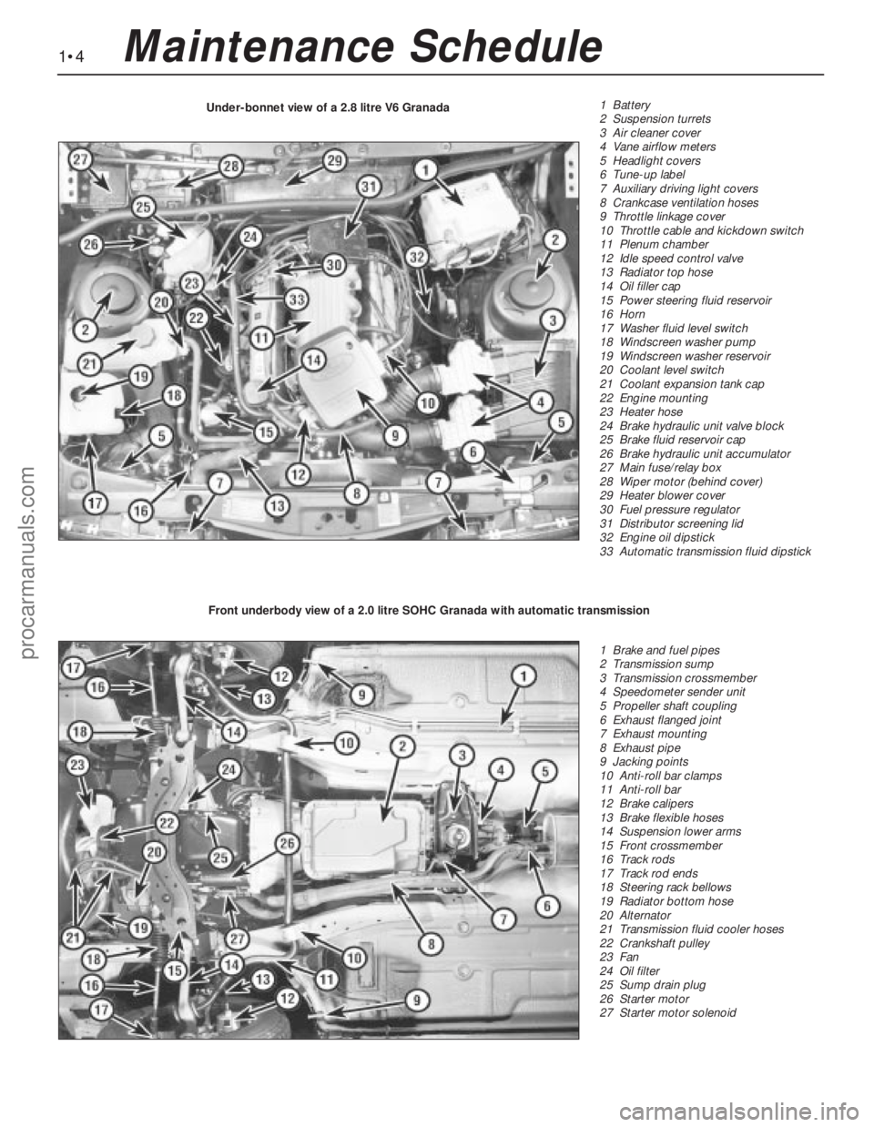
1•4Maintenance Schedule
1 Battery
2 Suspension turrets
3 Air cleaner cover
4 Vane airflow meters
5 Headlight covers
6 Tune-up label
7 Auxiliary driving light covers
8 Crankcase ventilation hoses
9 Throttle linkage cover
10 Throttle cable and kickdown switch
11 Plenum chamber
12 Idle speed control valve
13 Radiator top hose
14 Oil filler cap
15 Power steering fluid reservoir
16 Horn
17 Washer fluid level switch
18 Windscreen washer pump
19 Windscreen washer reservoir
20 Coolant level switch
21 Coolant expansion tank cap
22 Engine mounting
23 Heater hose
24 Brake hydraulic unit valve block
25 Brake fluid reservoir cap
26 Brake hydraulic unit accumulator
27 Main fuse/relay box
28 Wiper motor (behind cover)
29 Heater blower cover
30 Fuel pressure regulator
31 Distributor screening lid
32 Engine oil dipstick
33 Automatic transmission fluid dipstick Under-bonnet view of a 2.8 litre V6 Granada
1 Brake and fuel pipes
2 Transmission sump
3 Transmission crossmember
4 Speedometer sender unit
5 Propeller shaft coupling
6 Exhaust flanged joint
7 Exhaust mounting
8 Exhaust pipe
9 Jacking points
10 Anti-roll bar clamps
11 Anti-roll bar
12 Brake calipers
13 Brake flexible hoses
14 Suspension lower arms
15 Front crossmember
16 Track rods
17 Track rod ends
18 Steering rack bellows
19 Radiator bottom hose
20 Alternator
21 Transmission fluid cooler hoses
22 Crankshaft pulley
23 Fan
24 Oil filter
25 Sump drain plug
26 Starter motor
27 Starter motor solenoid Front underbody view of a 2.0 litre SOHC Granada with automatic transmission
procarmanuals.com
Page 6 of 255
1•5
1
Maintenance Schedule
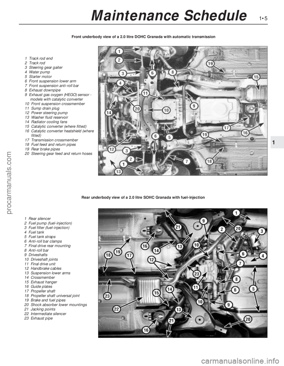
1 Track rod end
2 Track rod
3 Steering gear gaiter
4 Water pump
5 Starter motor
6 Front suspension lower arm
7 Front suspension anti-roll bar
8 Exhaust downpipe
9 Exhaust gas oxygen (HEGO) sensor -
models with catalytic converter
10 Front suspension crossmember
11 Sump drain plug
12 Power steering pump
13 Washer fluid reservoir
14 Radiator cooling fans
15 Catalytic converter (where fitted)
16 Catalytic converter heatshield (where
fitted)
17 Transmission crossmember
18 Fuel feed and return pipes
19 Rear brake pipes
20 Steering gear feed and return hosesFront underbody view of a 2.0 litre DOHC Granada with automatic transmission
1 Rear silencer
2 Fuel pump (fuel-injection)
3 Fuel filter (fuel-injection)
4 Fuel tank
5 Fuel tank straps
6 Anti-roll bar clamps
7 Final drive rear mounting
8 Anti-roll bar
9 Driveshafts
10 Driveshaft joints
11 Final drive unit
12 Handbrake cables
13 Suspension lower arms
14 Crossmember
15 Exhaust hanger
16 Guide plates
17 Propeller shaft
18 Propeller shaft universal joint
19 Brake and fuel pipes
20 Shock absorber lower mountings
21 Jacking points
22 Intermediate silencer
23 Exhaust pipe
Rear underbody view of a 2.0 litre SOHC Granada with fuel-injection
procarmanuals.com
Page 17 of 255
Instruments and electrical
equipment
1Check the operation of all instruments and
electrical equipment.
2Make sure that all instruments read
correctly, and switch on all electrical
equipment in turn to check that it functions
properly.
Steering and suspension
3Check for any abnormalities in the steering,
suspension, handling or road “feel”.
4Drive the vehicle, and check that there are
no unusual vibrations or noises.
5Check that the steering feels positive, with
no excessive “sloppiness”, or roughness, and
check for any suspension noises when
cornering, or when driving over bumps.
Drivetrain
6Check the performance of the engine,
clutch, transmission and driveshafts.
7Listen for any unusual noises from the
engine, clutch and transmission.
8Make sure that the engine runs smoothly
when idling, and that there is no hesitation
when accelerating.
9Where applicable, check that the clutch
action is smooth and progressive, that the
drive is taken up smoothly, and that the pedal
travel is not excessive. Also listen for any
noises when the clutch pedal is depressed.
10Check that all gears can be engaged
smoothly, without noise, and that the gear
lever action is not abnormally vague or
“notchy”.
Check the operation and
performance of the braking system
11Make sure that the vehicle does not pull to
one side when braking, and that the wheels do
not lock prematurely when braking hard.
12Check that there is no vibration through
the steering when braking.
13Check that the handbrake operates
correctly, without excessive movement of the
lever, and that it holds the vehicle stationary
on a slope.
14Test the operation of the brake servo unit
as follows. With the engine off, depress the
footbrake four or five times to exhaust the
vacuum. Start the engine, holding the brake
pedal depressed. As the engine starts, there
should be a noticeable “give” in the brake
pedal as vacuum builds up. Allow the engine
to run for at least two minutes, and then
switch it off. If the brake pedal is depressed
now, it should be possible to detect a hiss
from the servo as the pedal is depressed. After
about four or five applications, no further
hissing should be heard, and the pedal should
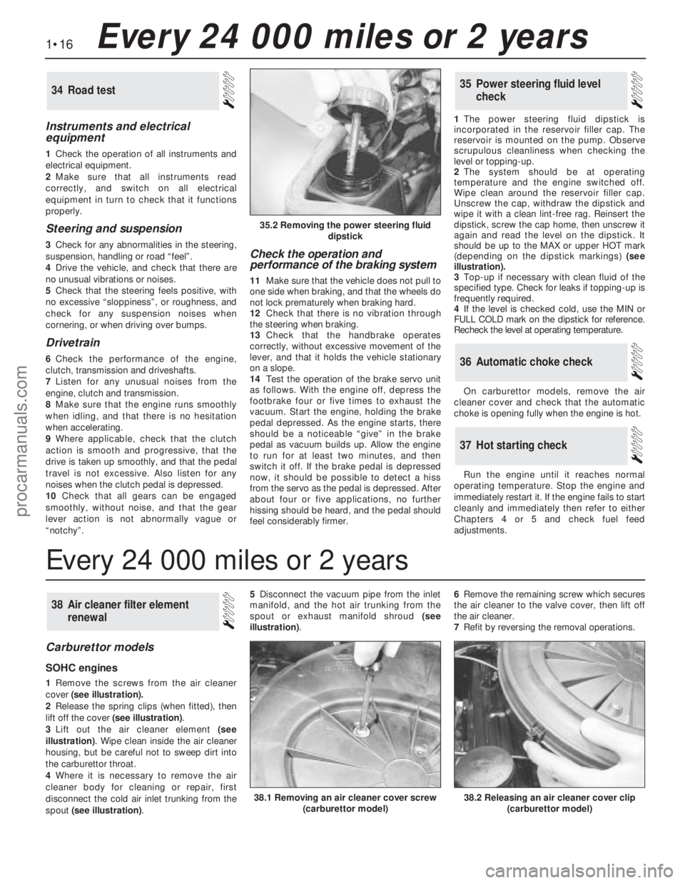
feel considerably firmer.1The power steering fluid dipstick is
incorporated in the reservoir filler cap. The
reservoir is mounted on the pump. Observe
scrupulous cleanliness when checking the
level or topping-up.
2The system should be at operating
temperature and the engine switched off.
Wipe clean around the reservoir filler cap.
Unscrew the cap, withdraw the dipstick and
wipe it with a clean lint-free rag. Reinsert the
dipstick, screw the cap home, then unscrew it
again and read the level on the dipstick. It
should be up to the MAX or upper HOT mark
(depending on the dipstick markings) (see
illustration).
3Top-up if necessary with clean fluid of the
specified type. Check for leaks if topping-up is
frequently required.
4If the level is checked cold, use the MIN or
FULL COLD mark on the dipstick for reference.
Recheck the level at operating temperature.
On carburettor models, remove the air
cleaner cover and check that the automatic
choke is opening fully when the engine is hot.
Run the engine until it reaches normal
operating temperature. Stop the engine and
immediately restart it. If the engine fails to start
cleanly and immediately then refer to either
Chapters 4 or 5 and check fuel feed
adjustments.
37Hot starting check
36Automatic choke check
35Power steering fluid level
check34Road test
Carburettor models
SOHC engines
1Remove the screws from the air cleaner
cover(see illustration).
2Release the spring clips (when fitted), then
lift off the cover (see illustration).
3Lift out the air cleaner element(see
illustration). Wipe clean inside the air cleaner
housing, but be careful not to sweep dirt into
the carburettor throat.
4Where it is necessary to remove the air
cleaner body for cleaning or repair, first
disconnect the cold air inlet trunking from the
spout (see illustration). 5Disconnect the vacuum pipe from the inlet
manifold, and the hot air trunking from the
spout or exhaust manifold shroud(see
illustration). 6Remove the remaining screw which secures
the air cleaner to the valve cover, then lift off
the air cleaner.
7Refit by reversing the removal operations.
38Air cleaner filter element
renewal
1•16Every 24 000 miles or 2 years
35.2 Removing the power steering fluid
dipstick
38.2 Releasing an air cleaner cover clip
(carburettor model)38.1 Removing an air cleaner cover screw
(carburettor model)
Every 24 000 miles or 2 years
procarmanuals.com
Page 43 of 255
See Chapter 1, Section 23.
1Make a final check to ensure that everything
has been reconnected to the engine and that no
rags or tools have been left in the engine bay.
2Check that oil and coolant levels are
correct.
3Start the engine. This may take a little longer
than usual as fuel is pumped up to the engine.
4Check that the oil pressure light goes out
when the engine starts.
5Run the engine at a fast tickover and check
for leaks of oil, fuel and coolant. Also check
power steering and transmission fluid cooler
unions, when applicable. Some smoke and
odd smells may be experienced as assembly
lubricant burns off the exhaust manifold and
other components.6Bring the engine to operating temperature.
Check the ignition timing then adjust the idle
speed (if applicable) and mixture.
7Stop the engine and allow it to cool, then re-
check the oil and coolant levels.
8If new bearings, pistons etc have been
fitted, the engine should be run in at reduced
speeds and loads for the first 500 miles (800
km) or so. It is beneficial to change the engine
oil and filter after this mileage.
1When engine performance is down, or if
misfiring occurs which cannot be attributed to
the ignition or fuel system, a compression test
can provide diagnostic clues. If the test is
performed regularly it can give warning of
trouble before any other symptoms become
apparent.
2The engine must be at operating
temperature, the battery must be fully charged
and the spark plugs must be removed. The
services of an assistant will also be required.
3Disable the ignition system by dismantlingthe coil LT feed. Fit the compression tester to
No 1 spark plug hole. (The type of tester which
screws into the spark plug hole is to be
preferred.)
4Have the assistant hold the throttle wide
open and crank the engine on the starter.
Record the highest reading obtained on the
compression tester.
5Repeat the test on the remaining cylinders,
recording the pressure developed in each.
6Desired pressures are given in the
Specifications. If the pressure in any cylinder
is low, introduce a teaspoonful of clean engine
oil into the spark plug hole and repeat the test.
7If the addition of oil temporarily improves
the compression pressure, this indicates that
bore or piston wear was responsible for the
pressure loss. No improvement suggests that
leaking or burnt valves, or a blown head
gasket, may be to blame.
8A low reading from two adjacent cylinders is
almost certainly due to the head gasket
between them having blown.
9On completion of the test, refit the spark
plugs and reconnect the coil LT feed.
52Compression test -
description and interpretation
51Initial start-up after overhaul
or major repair
50Valve clearances - checking
and adjustment
2A•20SOHCengines
procarmanuals.com
Page 47 of 255
manifold. Piston blow-by gases are drawn
through the oil separator and the vent valve to
the inlet manifold. The blow-by gases are then
drawn into the engine together with the fuel/air
mixture. Refer to Chapter 1 for maintenance of
the system.
The following operations can be carried out
without removing the engine from the vehicle.
a)Removal of the camshafts.
b)Removal and servicing of the cylinder
head.
c)Removal of the timing chain and
sprockets.
d)Removal of the oil pump.
e)Removal of the sump.
f)Removal of the pistons and connecting
rods.
g)Removal of the big-end bearings.
h)Removal of the engine mountings.
i)Removal of the clutch and flywheel.
j)Removal of the crankshaft front and rear
oil seals.
The following operations can only be carried
out after removing the engine from the vehicle.
a)Removal of the crankshaft main bearings.
b)Removal of the crankshaft.
Note: A hoist and lifting tackle will be required
to lift the engine out of the vehicle.
1Disconnect the battery negative lead.
2Remove the bonnet.
3On carburettor models, remove the air cleaner.
4On fuel-injection models, remove the air
inlet hose, plenum chamber and air cleaner lid
as an assembly.
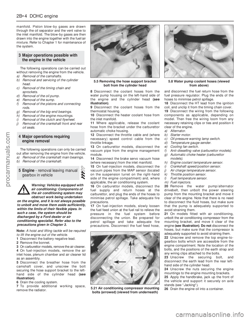
5Disconnect the breather hose from the
camshaft cover, and unscrew the bolt
securing the hose support bracket to the left-
hand side of the cylinder head (see
illustration).
6Drain the cooling system.
7To provide additional working space,
remove the radiator.8Disconnect the coolant hoses from the
water pump housing on the left-hand side of
the engine and the cylinder head (see
illustration).
9Disconnect the coolant hoses from the
thermostat housing.
10Disconnect the heater coolant hose from
the inlet manifold.
11Where applicable, release the coolant
hose from the bracket under the carburettor
automatic choke housing.
12Disconnect the throttle cable and (where
necessary) speed control cable from the
throttle linkage.
13On carburettor models, disconnect the
vacuum pipe from the engine management
module.
14Disconnect the brake servo vacuum hose
(where necessary) from the inlet manifold.
15On fuel-injection models, disconnect the
vacuum pipes from the MAP sensor (located
on the suspension turret on the right-hand
side of the engine compartment) and, where
applicable, the air conditioning system.
16On carburettor models, disconnect the
fuel supply and return hoses at the
carburettor, and plug the ends of the hoses to
minimise petrol spillage. Take adequate fire
precautions.
17On fuel-injection models, slowly loosen
the fuel feed union at the fuel rail to relieve the
pressure in the fuel system before
disconnecting the union. Be prepared for
petrol spillage and take adequate fire
precautions. Disconnect the fuel feed hose,and disconnect the fuel return hose from the
fuel pressure regulator. Plug the ends of the
hoses to minimise petrol spillage.
18Disconnect the HT lead from the ignition
coil, and unclip it from the timing chain cover.
19Disconnect the wiring from the following
components as applicable, depending on
model. Then free the wiring loom from any
necessary retaining clips or ties and position it
clear of the engine.
a)Alternator.
b)Starter motor.
c)Oil pressure warning lamp switch.
d)Temperature gauge sender.
e)Cooling fan switch.
f)Anti-dieselling valve (carburettor models).
g)Automatic choke heater (carburettor
models).
h)Engine coolant temperature sensor.
i)Crankshaft speed/position sensor.
j)Air charge temperature sensor.
k)Throttle position sensor.
l)Fuel temperature sensor.
m)Fuel injectors.
20Remove the water pump/alternator
drivebelt, then unbolt the power steering
pump from the mounting bracket and move it
clear of the engine. Note that there is no need
to disconnect the fluid hoses, but make sure
that the pump is adequately supported to
avoid straining them.
21On models fitted with air conditioning,
unbolt the air conditioning compressor from the
mounting bracket, and move it clear of the
engine (see illustration). Do notdisconnect the
hoses, but make sure that the compressor is
adequately supported to avoid straining them.
22Unscrew and remove the top engine-to-
gearbox bolts which are accessible from the
engine compartment. Note the location of the
bolts, and the positions of the earth strap and
any wiring clips attached to the bolts.
23Unscrew the securing bolt, and
disconnect the earth lead from the rear left-
hand side of the cylinder head.
24Unscrew the nuts securing the engine
mountings to the engine mounting brackets.
25Apply the handbrake, jack up the front of
the vehicle and support it securely on axle
stands (see “Jacking”).
26Drain the engine oil into a container.
5Engine - removal leaving manual
gearbox in vehicle
4Major operations requiring
engine removal
3Major operations possible with
the engine in the vehicle
2B•4DOHCengine
5.5 Removing the hose support bracket
bolt from the cylinder head5.8 Water pump coolant hoses (viewed
from above)
5.21 Air conditioning compressor mounting
bolts (arrowed) (viewed from underneath)
Warning: Vehicles equipped with
air conditioning: Components of
the air conditioning system may
obstruct work being undertaken
on the engine, and it is not always possible
to unbolt and move them aside sufficiently,
within the limits of their flexible pipes. In
such a case, the system should be
discharged by a Ford dealer or air
conditioning specialist. Refer also to the
precautions given in Chapter 3.
procarmanuals.com