1985 FORD GRANADA headlamp
[x] Cancel search: headlampPage 107 of 255

16Start the engine and note the engine
speed (rpm). The engine speed should
increase above the normal idle speed, and
should be as given in the Specifications.
17If the engine speed is not as specified,
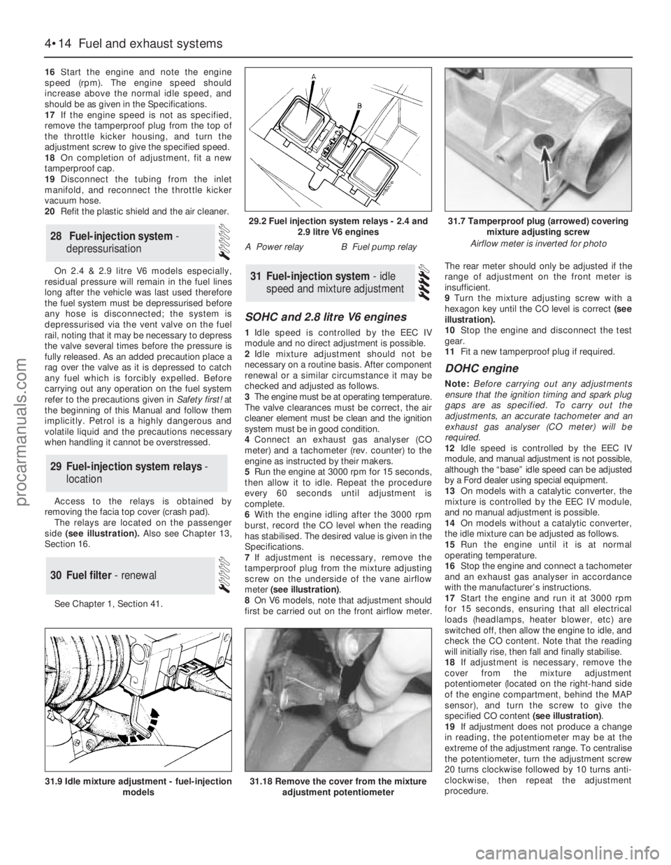
remove the tamperproof plug from the top of
the throttle kicker housing, and turn the
adjustment screw to give the specified speed.
18On completion of adjustment, fit a new
tamperproof cap.
19Disconnect the tubing from the inlet
manifold, and reconnect the throttle kicker
vacuum hose.
20Refit the plastic shield and the air cleaner.
On 2.4 & 2.9 litre V6 models especially,
residual pressure will remain in the fuel lines
long after the vehicle was last used therefore
the fuel system must be depressurised before
any hose is disconnected; the system is
depressurised via the vent valve on the fuel
rail, noting that it may be necessary to depress
the valve several times before the pressure is
fully released. As an added precaution place a
rag over the valve as it is depressed to catch
any fuel which is forcibly expelled. Before
carrying out any operation on the fuel system
refer to the precautions given in Safety first! at
the beginning of this Manual and follow them
implicitly. Petrol is a highly dangerous and
volatile liquid and the precautions necessary
when handling it cannot be overstressed.
Access to the relays is obtained by
removing the facia top cover (crash pad).
The relays are located on the passenger
side(see illustration). Also see Chapter 13,
Section 16.
See Chapter 1, Section 41.
SOHC and 2.8 litre V6 engines
1Idle speed is controlled by the EEC IV
module and no direct adjustment is possible.
2Idle mixture adjustment should not be
necessary on a routine basis. After component
renewal or a similar circumstance it may be
checked and adjusted as follows.
3The engine must be at operating temperature.
The valve clearances must be correct, the air
cleaner element must be clean and the ignition
system must be in good condition.
4Connect an exhaust gas analyser (CO
meter) and a tachometer (rev. counter) to the
engine as instructed by their makers.
5Run the engine at 3000 rpm for 15 seconds,
then allow it to idle. Repeat the procedure
every 60 seconds until adjustment is
complete.
6With the engine idling after the 3000 rpm
burst, record the CO level when the reading
has stabilised. The desired value is given in the
Specifications.
7If adjustment is necessary, remove the
tamperproof plug from the mixture adjusting
screw on the underside of the vane airflow
meter (see illustration).
8On V6 models, note that adjustment should
first be carried out on the front airflow meter.The rear meter should only be adjusted if the
range of adjustment on the front meter is
insufficient.
9Turn the mixture adjusting screw with a
hexagon key until the CO level is correct (see
illustration).
10Stop the engine and disconnect the test
gear.
11Fit a new tamperproof plug if required.
DOHC engine
Note: Before carrying out any adjustments
ensure that the ignition timing and spark plug
gaps are as specified. To carry out the
adjustments, an accurate tachometer and an
exhaust gas analyser (CO meter) will be
required.
12Idle speed is controlled by the EEC IV
module, and manual adjustment is not possible,
although the “base” idle speed can be adjusted
by a Ford dealer using special equipment.
13On models with a catalytic converter, the
mixture is controlled by the EEC IV module,
and no manual adjustment is possible.
14On models without a catalytic converter,
the idle mixture can be adjusted as follows.
15Run the engine until it is at normal
operating temperature.
16Stop the engine and connect a tachometer
and an exhaust gas analyser in accordance
with the manufacturer’s instructions.
17Start the engine and run it at 3000 rpm
for 15 seconds, ensuring that all electrical
loads (headlamps, heater blower, etc) are
switched off, then allow the engine to idle, and
check the CO content. Note that the reading
will initially rise, then fall and finally stabilise.
18If adjustment is necessary, remove the
cover from the mixture adjustment
potentiometer (located on the right-hand side
of the engine compartment, behind the MAP
sensor), and turn the screw to give the
specified CO content (see illustration).
19If adjustment does not produce a change
in reading, the potentiometer may be at the
extreme of the adjustment range. To centralise
the potentiometer, turn the adjustment screw
20 turns clockwise followed by 10 turns anti-
clockwise, then repeat the adjustment
procedure.
31Fuel-injection system - idle
speed and mixture adjustment
30Fuel filter - renewal
29Fuel-injection system relays -
location
28Fuel-injection system -
depressurisation
4•14Fuel and exhaust systems
31.18 Remove the cover from the mixture
adjustment potentiometer31.9 Idle mixture adjustment - fuel-injection
models
29.2 Fuel injection system relays - 2.4 and
2.9 litre V6 engines
A Power relayB Fuel pump relay
31.7 Tamperproof plug (arrowed) covering
mixture adjusting screw
Airflow meter is inverted for photo
procarmanuals.com
Page 167 of 255

Later models
7The radiator grille of these models can be
removed and refitted as described above,
noting that it will also be necessary to remove
the headlamp wiper arms (where fitted) before
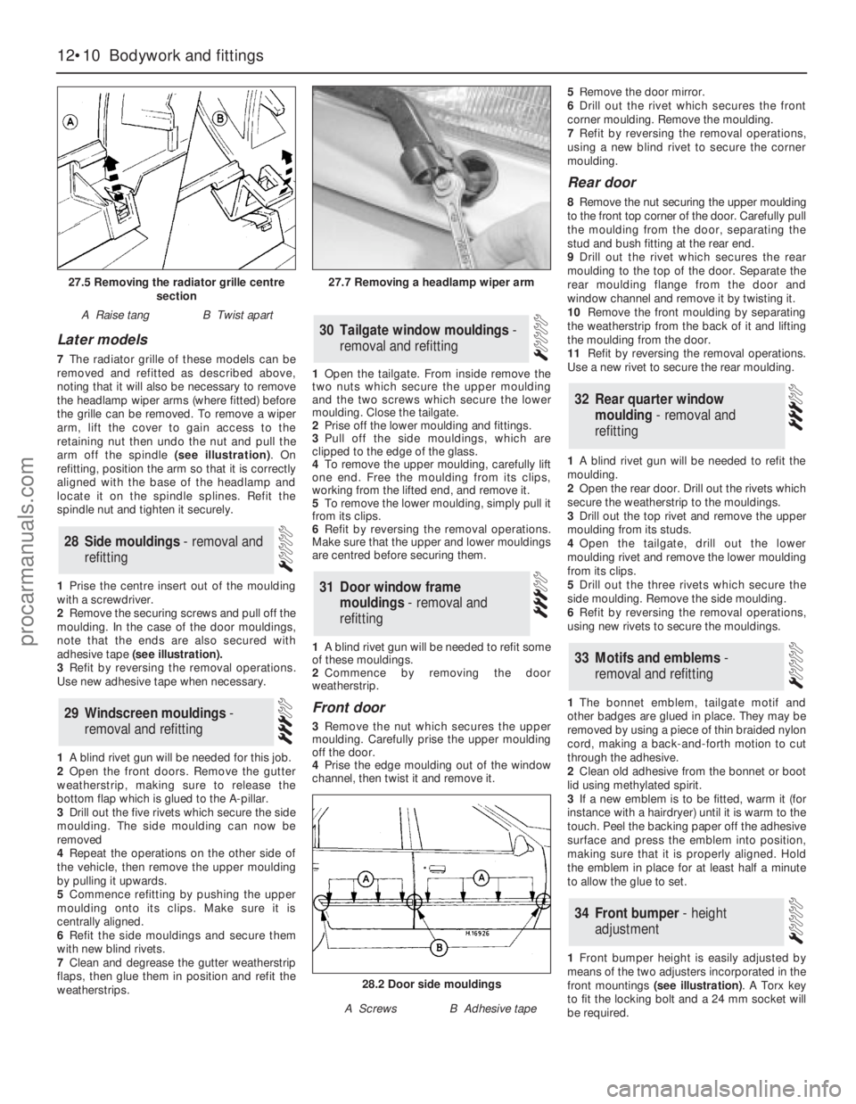
the grille can be removed. To remove a wiper
arm, lift the cover to gain access to the
retaining nut then undo the nut and pull the
arm off the spindle (see illustration). On
refitting, position the arm so that it is correctly
aligned with the base of the headlamp and
locate it on the spindle splines. Refit the
spindle nut and tighten it securely.
1Prise the centre insert out of the moulding
with a screwdriver.
2Remove the securing screws and pull off the
moulding. In the case of the door mouldings,
note that the ends are also secured with
adhesive tape (see illustration).
3Refit by reversing the removal operations.
Use new adhesive tape when necessary.
1A blind rivet gun will be needed for this job.
2Open the front doors. Remove the gutter
weatherstrip, making sure to release the
bottom flap which is glued to the A-pillar.
3Drill out the five rivets which secure the side
moulding. The side moulding can now be
removed
4Repeat the operations on the other side of
the vehicle, then remove the upper moulding
by pulling it upwards.
5Commence refitting by pushing the upper
moulding onto its clips. Make sure it is
centrally aligned.
6Refit the side mouldings and secure them
with new blind rivets.
7Clean and degrease the gutter weatherstrip
flaps, then glue them in position and refit the
weatherstrips.1Open the tailgate. From inside remove the
two nuts which secure the upper moulding
and the two screws which secure the lower
moulding. Close the tailgate.
2Prise off the lower moulding and fittings.
3Pull off the side mouldings, which are
clipped to the edge of the glass.
4To remove the upper moulding, carefully lift
one end. Free the moulding from its clips,
working from the lifted end, and remove it.
5To remove the lower moulding, simply pull it
from its clips.
6Refit by reversing the removal operations.
Make sure that the upper and lower mouldings
are centred before securing them.
1A blind rivet gun will be needed to refit some
of these mouldings.
2Commence by removing the door
weatherstrip.
Front door
3Remove the nut which secures the upper
moulding. Carefully prise the upper moulding
off the door.
4Prise the edge moulding out of the window
channel, then twist it and remove it. 5Remove the door mirror.
6Drill out the rivet which secures the front
corner moulding. Remove the moulding.
7Refit by reversing the removal operations,
using a new blind rivet to secure the corner
moulding.
Rear door
8Remove the nut securing the upper moulding
to the front top corner of the door. Carefully pull
the moulding from the door, separating the
stud and bush fitting at the rear end.
9Drill out the rivet which secures the rear
moulding to the top of the door. Separate the
rear moulding flange from the door and
window channel and remove it by twisting it.
10Remove the front moulding by separating
the weatherstrip from the back of it and lifting
the moulding from the door.
11Refit by reversing the removal operations.
Use a new rivet to secure the rear moulding.
1A blind rivet gun will be needed to refit the
moulding.
2Open the rear door. Drill out the rivets which
secure the weatherstrip to the mouldings.
3Drill out the top rivet and remove the upper
moulding from its studs.
4Open the tailgate, drill out the lower
moulding rivet and remove the lower moulding
from its clips.
5Drill out the three rivets which secure the
side moulding. Remove the side moulding.
6Refit by reversing the removal operations,
using new rivets to secure the mouldings.
1The bonnet emblem, tailgate motif and
other badges are glued in place. They may be
removed by using a piece of thin braided nylon
cord, making a back-and-forth motion to cut
through the adhesive.
2Clean old adhesive from the bonnet or boot
lid using methylated spirit.
3If a new emblem is to be fitted, warm it (for
instance with a hairdryer) until it is warm to the
touch. Peel the backing paper off the adhesive
surface and press the emblem into position,
making sure that it is properly aligned. Hold
the emblem in place for at least half a minute
to allow the glue to set.
1Front bumper height is easily adjusted by
means of the two adjusters incorporated in the
front mountings (see illustration). A Torx key
to fit the locking bolt and a 24 mm socket will
be required.
34Front bumper - height
adjustment
33Motifs and emblems -
removal and refitting
32Rear quarter window
moulding - removal and
refitting
31Door window frame
mouldings - removal and
refitting
30Tailgate window mouldings -
removal and refitting
29Windscreen mouldings -
removal and refitting
28Side mouldings - removal and
refitting
12•10Bodywork and fittings
27.5 Removing the radiator grille centre
section
A Raise tangB Twist apart
27.7 Removing a headlamp wiper arm
28.2 Door side mouldings
A ScrewsB Adhesive tape
procarmanuals.com
Page 184 of 255

Estate
19This procedure is the same as described
above for the Saloon models noting that it is
necessary to remove the luggage
compartment side trim panel to gain access to
the light cluster retaining nuts.
1It is recommended that beam adjustment be
carried out by a Ford garage using optical
alignment equipment. In an emergency,
however, the following procedure will produce
acceptable results.
2The vehicle should be normally laden and the
tyre pressures must be correct. Park the vehicle
on level ground, approximately 10 metres (33
feet) in front of a flat wall or garage door.
3Draw a vertical line on the wall or door
corresponding to the centre-line of the vehicle.
(The position of this line can be determined by
marking the centres of the windscreen and
rear window with crayon, then viewing the wall
or door from the rear of the vehicle.)
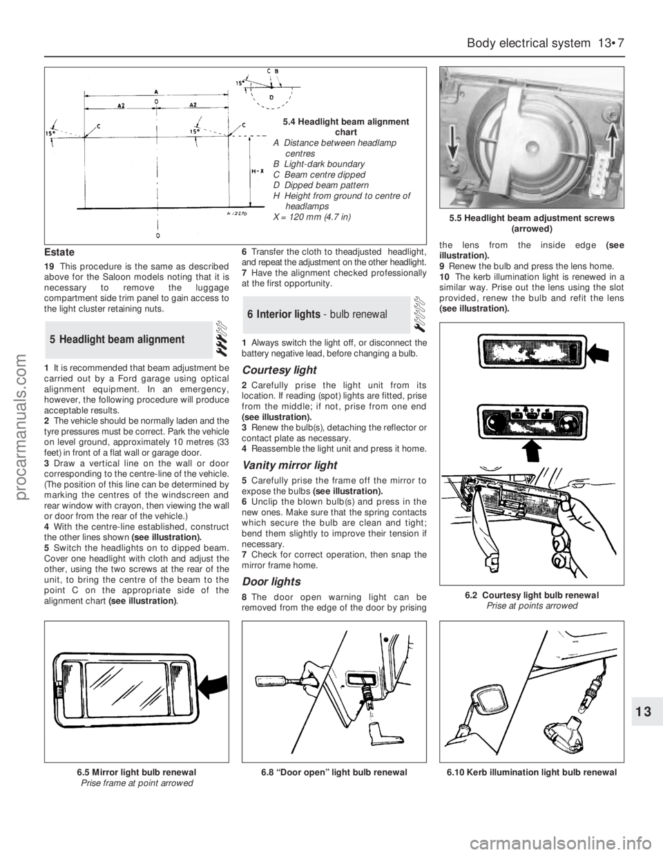
4With the centre-line established, construct
the other lines shown (see illustration).
5Switch the headlights on to dipped beam.
Cover one headlight with cloth and adjust the
other, using the two screws at the rear of the
unit, to bring the centre of the beam to the
point C on the appropriate side of the
alignment chart (see illustration).6Transfer the cloth to theadjusted headlight,
and repeat the adjustment on the other headlight.
7Have the alignment checked professionally
at the first opportunity.
1Always switch the light off, or disconnect the
battery negative lead, before changing a bulb.
Courtesy light
2Carefully prise the light unit from its
location. If reading (spot) lights are fitted, prise
from the middle; if not, prise from one end
(seeillustration).
3Renew the bulb(s), detaching the reflector or
contact plate as necessary.
4Reassemble the light unit and press it home.
Vanity mirror light
5Carefully prise the frame off the mirror to
expose the bulbs(see illustration).
6Unclip the blown bulb(s) and press in the
new ones. Make sure that the spring contacts
which secure the bulb are clean and tight;
bend them slightly to improve their tension if
necessary.
7Check for correct operation, then snap the
mirror frame home.
Door lights
8The door open warning light can be
removed from the edge of the door by prisingthe lens from the inside edge (see
illustration).
9Renew the bulb and press the lens home.
10The kerb illumination light is renewed in a
similar way. Prise out the lens using the slot
provided, renew the bulb and refit the lens
(seeillustration).
6Interior lights - bulb renewal
5Headlight beam alignment
Body electrical system 13•7
13
5.5 Headlight beam adjustment screws
(arrowed)
6.2 Courtesy light bulb renewal
Prise at points arrowed
6.8 “Door open” light bulb renewal6.5 Mirror light bulb renewal
Prise frame at point arrowed
5.4 Headlight beam alignment
chart
A Distance between headlamp
centres
B Light-dark boundary
C Beam centre dipped
D Dipped beam pattern
H Height from ground to centre of
headlamps
X = 120 mm (4.7 in)
6.10 Kerb illumination light bulb renewal
procarmanuals.com