1985 FORD GRANADA instrument cluster
[x] Cancel search: instrument clusterPage 90 of 255
See Chapter 1, Section 21.
1On 2.0 litre DOHC engines only, remove the
water pump/alternator drivebelt as described
in the previous Section.
2Loosen the alternator lower mounting
through-bolt, then remove the alternator upper
mounting bolt, and swing the alternator away
from the engine.
3Unscrew the central securing bolt, and
withdraw the drivebelt tensioner assembly.
4Commence refitting by positioning the
tensioner on the cylinder block, ensuring that
the lug on the rear of the tensioner bracket
engages with the corresponding hole in the
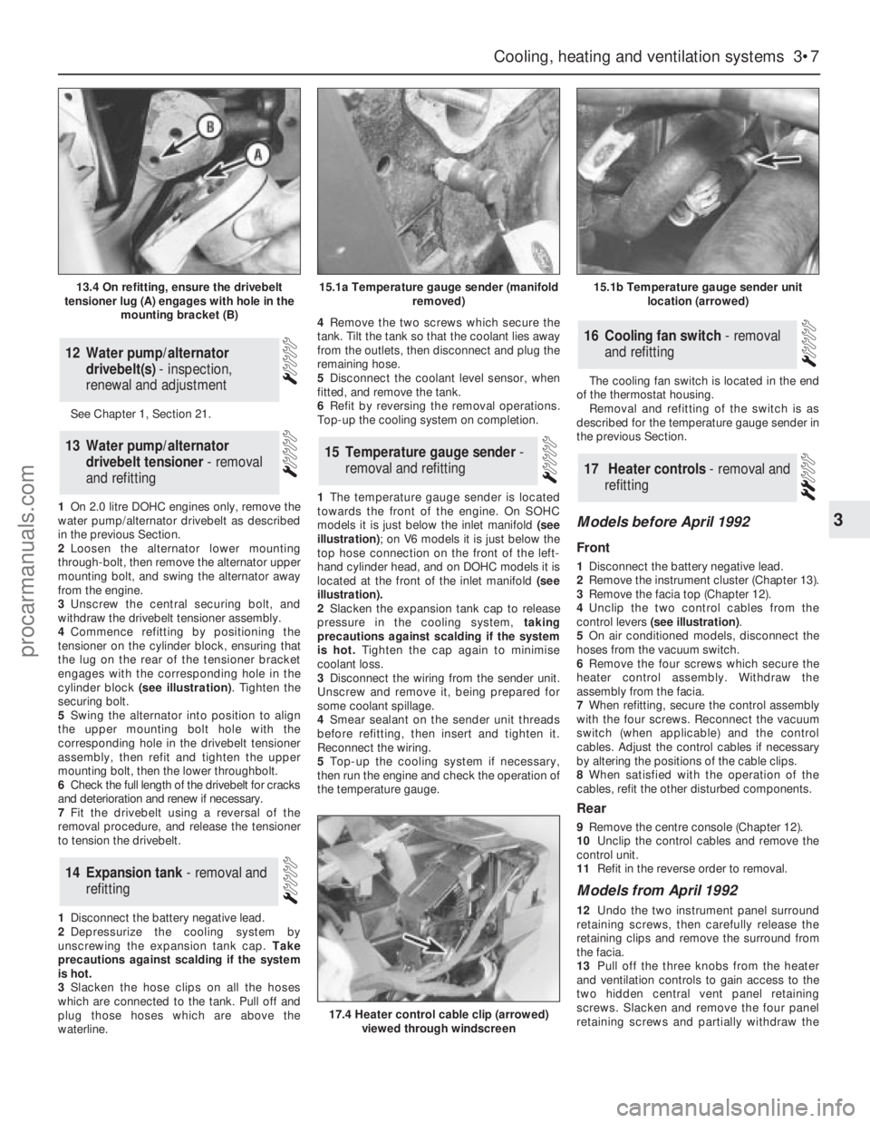
cylinder block (see illustration). Tighten the
securing bolt.
5Swing the alternator into position to align
the upper mounting bolt hole with the
corresponding hole in the drivebelt tensioner
assembly, then refit and tighten the upper
mounting bolt, then the lower throughbolt.
6Check the full length of the drivebelt for cracks
and deterioration and renew if necessary.
7Fit the drivebelt using a reversal of the
removal procedure, and release the tensioner
to tension the drivebelt.
1Disconnect the battery negative lead.
2Depressurize the cooling system by
unscrewing the expansion tank cap. Take
precautions against scalding if the system
is hot.
3Slacken the hose clips on all the hoses
which are connected to the tank. Pull off and
plug those hoses which are above the
waterline.4Remove the two screws which secure the
tank. Tilt the tank so that the coolant lies away
from the outlets, then disconnect and plug the
remaining hose.
5Disconnect the coolant level sensor, when
fitted, and remove the tank.
6Refit by reversing the removal operations.
Top-up the cooling system on completion.
1The temperature gauge sender is located
towards the front of the engine. On SOHC
models it is just below the inlet manifold (see
illustration); on V6 models it is just below the
top hose connection on the front of the left-
hand cylinder head, and on DOHC models it is
located at the front of the inlet manifold (see
illustration).
2Slacken the expansion tank cap to release
pressure in the cooling system, taking
precautions against scalding if the system
is hot.Tighten the cap again to minimise
coolant loss.
3Disconnect the wiring from the sender unit.
Unscrew and remove it, being prepared for
some coolant spillage.
4Smear sealant on the sender unit threads
before refitting, then insert and tighten it.
Reconnect the wiring.
5Top-up the cooling system if necessary,
then run the engine and check the operation of
the temperature gauge.The cooling fan switch is located in the end
of the thermostat housing.
Removal and refitting of the switch is as
described for the temperature gauge sender in
the previous Section.
Models before April 1992
Front
1Disconnect the battery negative lead.
2Remove the instrument cluster (Chapter 13).
3Remove the facia top (Chapter 12).
4Unclip the two control cables from the
control levers (see illustration).
5On air conditioned models, disconnect the
hoses from the vacuum switch.
6Remove the four screws which secure the
heater control assembly. Withdraw the
assembly from the facia.
7When refitting, secure the control assembly
with the four screws. Reconnect the vacuum
switch (when applicable) and the control
cables. Adjust the control cables if necessary
by altering the positions of the cable clips.
8When satisfied with the operation of the
cables, refit the other disturbed components.
Rear
9Remove the centre console (Chapter 12).
10Unclip the control cables and remove the
control unit.
11Refit in the reverse order to removal.
Models from April 1992
12Undo the two instrument panel surround
retaining screws, then carefully release the
retaining clips and remove the surround from
the facia.
13Pull off the three knobs from the heater
and ventilation controls to gain access to the
two hidden central vent panel retaining
screws. Slacken and remove the four panel
retaining screws and partially withdraw the
17Heater controls - removal and
refitting
16Cooling fan switch - removal
and refitting
15Temperature gauge sender -
removal and refitting
14Expansion tank - removal and
refitting
13Water pump/alternator
drivebelt tensioner - removal
and refitting
12Water pump/alternator
drivebelt(s) - inspection,
renewal and adjustment
Cooling, heating and ventilation systems 3•7
3
13.4 On refitting, ensure the drivebelt
tensioner lug (A) engages with hole in the
mounting bracket (B)15.1a Temperature gauge sender (manifold
removed)15.1b Temperature gauge sender unit
location (arrowed)
17.4 Heater control cable clip (arrowed)
viewed through windscreen
procarmanuals.com
Page 91 of 255
panel. Disconnect the wiring connectors from
the heated window switches and fuel
computer (where fitted) and remove the panel
from the car.
14Undo the two retaining screws then
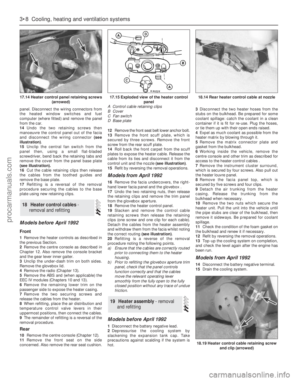
manoeuvre the control panel out of the facia
and disconnect the wiring connector (see
illustration).
15Unclip the central fan switch from the
panel then, using a small flat-bladed
screwdriver, bend back the retaining tabs and
remove the cover from the panel base plate
(see illustration).
16Cut the cable retaining clips then release
the cables from the toothed guides and
remove the base plate.
17Refitting is a reversal of the removal
procedure securing the cables to the base
plate using new retaining clips.
Models before April 1992
Front
1Remove the heater controls as described in
the previous Section.
2Remove the centre console as described in
Chapter 12. Also remove the console bracket
and the gear lever inner gaiter.
3Unclip the under-dash trim on both sides.
Remove the glovebox lid.
4Remove the radio (Chapter 13).
5Remove the ABS and (when applicable) the
EEC IV modules (Chapters 10 and 13).
6Remove the remaining lower trim on the
passenger side to expose the heater casing.
7Remove the two securing screws and
release the cables from the heater.
8When refitting, place the air distribution and
temperature control valve levers in their
uppermost positions, then connect the cables.
9The remainder of refitting is a reversal of the
removal procedure.
Rear
10Remove the centre console (Chapter 12).
11Remove the front seat on the side
concerned. Also remove the rear seat cushion. 12Remove the front seat belt lower anchor bolt.
13Remove the front scuff plate, which is
secured by three screws. Remove the front
screw from the rear scuff plate.
14Roll back the front carpet from the scuff
plates to expose the heater cable. Release the
cable from its ties and disconnect it from the
control unit and the nozzle (see illustration).
15Refit by reversing the removal operations.
Models from April 1992
16Remove the facia undercovers, the right-
hand lower facia panel and the glovebox .
17Undo the two retaining nuts, then release
the retaining clips and remove the trim panel
from the glovebox aperture.
18Remove the heater control panel.
19Slacken and remove the control cable
retaining screws then release the retaining
clips (one screw and one clip for each cable).
Detach the cables from the heater assembly
and withdraw them from the facia whilst noting
the correct routing (see illustration).
20Refitting is a reverse of the removal
procedure noting the following points.
a)Ensure that the cables are correctly routed
prior to connecting them to the heater
housing.
b)Prior to refitting the glovebox aperture trim
panel, check that the panel controls
function correctly and that the cables
move the relevant operating lever
smoothly from the fully open to the fully
closed position without any trace of undue
friction.
Models before April 1992
1Disconnect the battery negative lead.
2Depressurise the cooling system by
slackening the expansion tank cap. Take
precautions against scalding if the system is
hot.3Disconnect the two heater hoses from the
stubs on the bulkhead. Be prepared for some
coolant spillage: catch the coolant in a clean
container if it is fit for re-use. Plug the hoses,
or tie them up with their open ends raised.
4Expel as much coolant as possible from the
heater matrix by blowing through it.
5Remove the matrix connector plate and
gasket from the bulkhead.
6Working inside the vehicle, remove the
centre console and other trim as described for
access to the heater control cables .
7Remove the instrument cluster surround,
which is secured by four screws. Also pull out
the heater louvre panel.
8Remove the facia panel top, which is
secured by five screws and four clips.
9Detach the air trunking from the heater
casing. Release the trunking from the
bulkhead when necessary.
10Remove the two nuts which secure the
heater unit. Pull the unit into the vehicle until
the pipe stubs are clear of the bulkhead, then
remove it sideways. Be prepared for coolant
spillage.
11Check the condition of the foam gasket on
the bulkhead and renew it if necessary.
12Refit by reversing the removal operations.
13Top-up the cooling system on completion,
and check the level again after the engine has
been run.
Models from April 1992
14Disconnect the battery negative terminal.
15Drain the cooling system.
19Heater assembly - removal
and refitting
18Heater control cables -
removal and refitting
3•8Cooling, heating and ventilation systems
17.14 Heater control panel retaining screws
(arrowed)
18.19 Heater control cable retaining screw
and clip (arrowed)
17.15 Exploded view of the heater control
panel
A Control cable retaining clips
B Cover
C Fan switch
D Base plate18.14 Rear heater control cable at nozzle
procarmanuals.com
Page 131 of 255
Models covered in this Manual have disc
brakes fitted all round. The footbrake operates
hydraulically on all four wheels, and the
handbrake operates mechanically on the rear
wheels. Both footbrake and handbrake are
self-adjusting in use.
Ford’s anti-lock braking system (ABS) is
fitted to all models. The system monitors the
rotational speed of each roadwheel. When a
wheel begins to lock under heavy braking, the
ABS reduces the hydraulic pressure to that
wheel, so preventing it from locking. When this
happens a pulsating effect will be noticed at
the brake pedal. On some road surfaces the
tyres may squeal when braking hard even
though the wheels are not locked.
The main components of the system are the
hydraulic unit, the calipers, pads and discs,
the wheel sensors and the “brain” or control
module. The hydraulic unit contains the
elements of a traditional master cylinder, plus
an electric motor and pump, a pressure
accumulator and control valves. The pump is
the source of pressure for the system and
does away with the need for a vacuum servo.
The hydraulic circuit is split front and rear,
as is normal practice with rear-wheel drive
vehicles. In the event that the hydraulic pump
fails, unassisted braking effort is still available
on the front calipers only.
Warning lights inform the driver of low brake
fluid level, ABS failure and (on some models)
brake pad wear. The low fluid level light
doubles as a “handbrake on” light; if it
illuminates at the same time as the ABS
warning light, it warns of low hydraulic
pressure.
ABS cannot overturn the laws of physics:
stopping distances will inevitably be greater on
loose or slippery surfaces. However, the system
should allow even inexperienced drivers to
retain directional control under panic braking.
From August 1986 the following
modifications were made to the braking
system.
a)The relays differ from earlier versions.b)The hydraulic pump is constructed of iron
rather than alloy.
c)A new pressure warning switch is used.
d)The earlier high pressure rubber hose is
replaced by a steel pipe.
To overcome the problem of excessive rear
brake pad wear, Ford introduced a differential
valve which is screwed into the ABS valve
block.The valve limits the pressure applied to
the rear brake calipers and so reduces brake
pad wear. From 1988 onwards, the valve has
been fitted during production. The differential
valve can also be fitted to earlier models. Refer
to your Ford dealer for further information.
From April 1992 onwards, the models
covered in this Manual were equipped with a
new Teves MK IV anti-lock braking system
instead of the Teves MK II system fitted to the
earlier models.
The Teves MK IV system differs from the
earlier MK II system in the following ways.
a)The source of hydraulic pressure for the
system is a conventional master cylinder
and vacuum servo assembly.
b)A valve block and pump assembly is used
instead of the hydraulic control unit. The
block contains the inlet and outlet
solenoid valves that control the hydraulic
system. There are three pairs of valves,
one for each brake circuit (paragraph c).
c)The hydraulic braking system consists of
three separate circuits; one for each front
brake (which are totally independent of
each other), and a joint circuit which
operates both rear brakes.
d)A G (gravity) switch is incorporated in the
system. This is an inertia type switch and
informs the control module when the
vehicle is decelerating rapidly.
e)A Pedal Travel Sensor (PTS) is fitted to the
vacuum servo unit. The PTS informs the
control module of the position of the brake
pedal when the anti-lock sequence starts
and ensures that a constant pedal height
is maintained during the sequence.
The MK IV system operates as follows.
During normal operation the system
functions in the same way as a non-ABS
system would. During this time the three inlet
valves in the valve block are open and theoutlet valves are closed, allowing full hydraulic
pressure present in the master cylinder to act
on the main braking circuit. If the control
module receives a signal from one of the
wheel sensors and senses that a wheel is
about to lock, it closes the relevant inlet valve
in the valve block which then isolates the
brake caliper on the wheel which is about to
lock from the master cylinder, effectively
sealing in the hydraulic pressure. If the speed
of rotation of the wheel continues to decrease
at an abnormal rate, the control module will
then open the relevant outlet valve in the valve
block; this allows the fluid from the relevant
hydraulic circuit to return to the master
cylinder reservoir, releasing pressure on the
brake caliper so that the brake is released. The
pump in the valve block also operates to assist
in the quick release of pressure. Once the
speed of rotation of the wheel returns to an
acceptable rate the pump stops, the outlet
valve closes and the inlet valve is opened,
allowing the hydraulic master cylinder
pressure to return to the caliper which then
reapplies the brake. This cycle can be carried
many times a second. The solenoid valves
connected to the front calipers operate
independently, but the valve connected to the
rear calipers operates both calipers
simultaneously.
The operation of the ABS system is entirely
dependent on electrical signals. To prevent
the system responding to any inaccurate
signals, a built-in safety circuit monitors all
signals received by the control module. If an
inaccurate signal or low battery voltage is
detected, the ABS system is automatically
shut down and the warning lamp on the
instrument cluster is illuminated to inform the
driver that the ABS system is not operational.
Whilst in this state the system functions in the
same way as a non-ABS system would. If a
fault does develop in the ABS system, the car
must be taken to a Ford dealer for fault
diagnosis and repair. The system is equipped
with a diagnostic plug into which a special
diagnostic (STAR) tester can be plugged. This
allows faults to be easily traced.
1General information
10•2Braking system
Torque wrench settingsNmlbf ft
Front caliper:
To stub axle carrier . . . . . . . . . . . . . . . . . . . . . . . . . . . . . . . . . . . . . . .51 to 6138 to 45
Slide bolts . . . . . . . . . . . . . . . . . . . . . . . . . . . . . . . . . . . . . . . . . . . . . .20 to 2515 to 18
Rear caliper:
Bracket to carrier plate . . . . . . . . . . . . . . . . . . . . . . . . . . . . . . . . . . . .51 to 6138 to 45
Slide bolts . . . . . . . . . . . . . . . . . . . . . . . . . . . . . . . . . . . . . . . . . . . . . .31 to 3523 to 26
Hydraulic unit to bulkhead . . . . . . . . . . . . . . . . . . . . . . . . . . . . . . . . . . .41 to 5130 to 38
Accumulator to pump body . . . . . . . . . . . . . . . . . . . . . . . . . . . . . . . . . .35 to 4526 to 33
Pump mounting bolts . . . . . . . . . . . . . . . . . . . . . . . . . . . . . . . . . . . . . . .7 to 95 to 7
High pressure hose banjo bolts . . . . . . . . . . . . . . . . . . . . . . . . . . . . . . .16 to 2412 to 18
Reservoir mounting bolts . . . . . . . . . . . . . . . . . . . . . . . . . . . . . . . . . . . .4 to 63 to 4
Wheel sensor fixing bolts . . . . . . . . . . . . . . . . . . . . . . . . . . . . . . . . . . . .8 to 116 to 8
Vacuum servo unit retaining nuts (Teves MK IV) . . . . . . . . . . . . . . . . . .35 to 4526 to 33
Master cylinder retaining nuts (Teves MK IV) . . . . . . . . . . . . . . . . . . . . .20 to 2515 to 18
Valve block and pump assembly mounting nuts (Teves MK IV) . . . . . . .21 to 2815 to 21
procarmanuals.com
Page 170 of 255
6Disconnect the glovebox arms and hinges.
Withdraw the hinge pins and remove the lid.
7Slide the auxiliary fuse panel off its
mounting and remove the glovebox light
(when fitted).
8Remove the ABS and ESC/EEC modules
(Chapter 13). Remove the two nuts and
washers from inside the glovebox.
9Remove the radio, stowage box or graphic
equaliser, ashtray, cigarette lighter panel and
(when applicable) the gear lever gaiter.
10Remove the centre console, disconnecting
switches, rear heater controls etc as
necessary.
11Remove the six screws which secure the
passenger’s side lower panel. Remove the
panel. 12Refit by reversing the removal operations,
transferring the brackets, captive nuts or other
fittings to any new panels being fitted.
Models from April 1992
13Disconnect the battery negative terminal.
14Remove the centre console.
15Remove the radio, amplifier unit and
(where necessary) the CD player.
16Remove the instrument cluster.
17Remove the steering wheel and then the
steering column direction indicator/headlight
flasher switch and windscreen wipe/wash
switch.
18Pull off the three knobs from the heater
and ventilation controls to gain access to the
two hidden central vent panel retainingscrews. Slacken and remove the four panel
retaining screws and partially withdraw the
panel. Disconnect the wiring connectors from
the heated window switches and fuel
computer (where fitted) and remove the panel
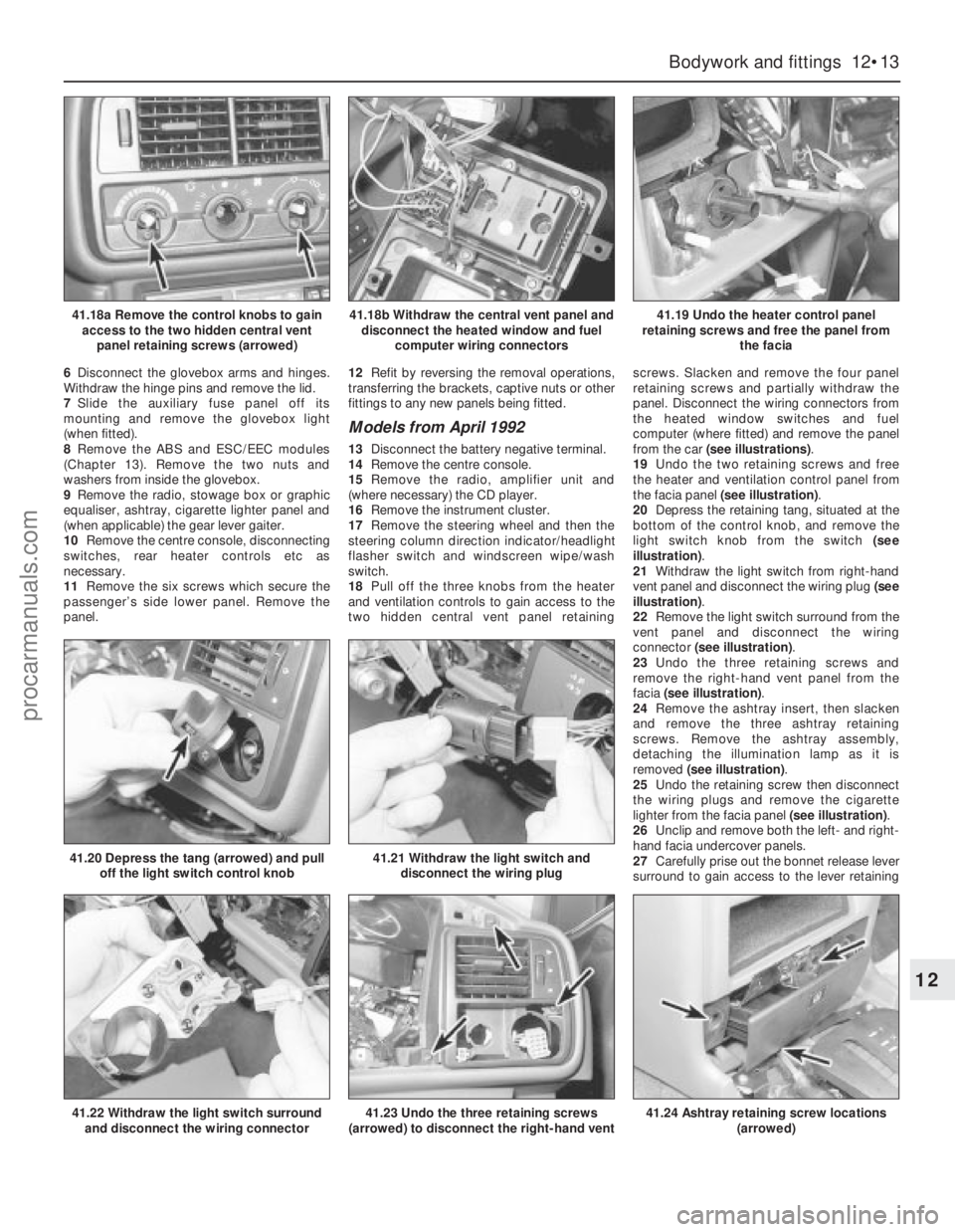
from the car (see illustrations).
19Undo the two retaining screws and free
the heater and ventilation control panel from
the facia panel (see illustration).
20Depress the retaining tang, situated at the
bottom of the control knob, and remove the
light switch knob from the switch (see
illustration).
21Withdraw the light switch from right-hand
vent panel and disconnect the wiring plug (see
illustration).
22Remove the light switch surround from the
vent panel and disconnect the wiring
connector (see illustration).
23Undo the three retaining screws and
remove the right-hand vent panel from the
facia (see illustration).
24Remove the ashtray insert, then slacken
and remove the three ashtray retaining
screws. Remove the ashtray assembly,
detaching the illumination lamp as it is
removed (see illustration).
25Undo the retaining screw then disconnect
the wiring plugs and remove the cigarette
lighter from the facia panel (see illustration).
26Unclip and remove both the left- and right-
hand facia undercover panels.
27Carefully prise out the bonnet release lever
surround to gain access to the lever retaining
Bodywork and fittings 12•13
12
41.18a Remove the control knobs to gain
access to the two hidden central vent
panel retaining screws (arrowed)41.18b Withdraw the central vent panel and
disconnect the heated window and fuel
computer wiring connectors41.19 Undo the heater control panel
retaining screws and free the panel from
the facia
41.22 Withdraw the light switch surround
and disconnect the wiring connector
41.20 Depress the tang (arrowed) and pull
off the light switch control knob41.21 Withdraw the light switch and
disconnect the wiring plug
41.23 Undo the three retaining screws
(arrowed) to disconnect the right-hand vent41.24 Ashtray retaining screw locations
(arrowed)
procarmanuals.com
Page 172 of 255
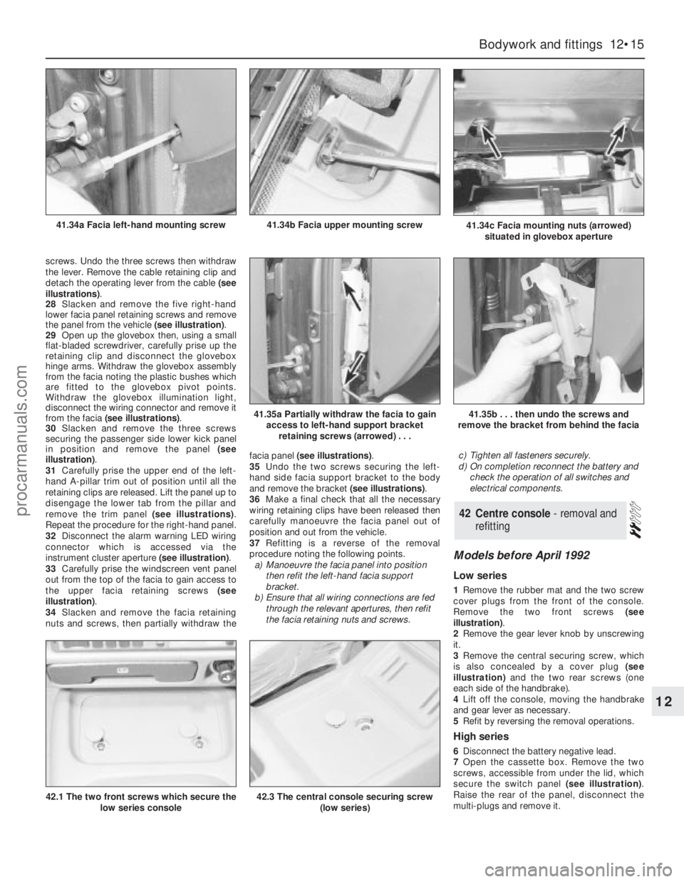
screws. Undo the three screws then withdraw
the lever. Remove the cable retaining clip and
detach the operating lever from the cable (see
illustrations).
28Slacken and remove the five right-hand
lower facia panel retaining screws and remove
the panel from the vehicle (see illustration).
29Open up the glovebox then, using a small
flat-bladed screwdriver, carefully prise up the
retaining clip and disconnect the glovebox
hinge arms. Withdraw the glovebox assembly
from the facia noting the plastic bushes which
are fitted to the glovebox pivot points.
Withdraw the glovebox illumination light,
disconnect the wiring connector and remove it
from the facia (see illustrations).
30Slacken and remove the three screws
securing the passenger side lower kick panel
in position and remove the panel (see
illustration).
31Carefully prise the upper end of the left-
hand A-pillar trim out of position until all the
retaining clips are released. Lift the panel up to
disengage the lower tab from the pillar and
remove the trim panel (see illustrations).
Repeat the procedure for the right-hand panel.
32Disconnect the alarm warning LED wiring
connector which is accessed via the
instrument cluster aperture (see illustration).
33Carefully prise the windscreen vent panel
out from the top of the facia to gain access to
the upper facia retaining screws (see
illustration).
34Slacken and remove the facia retaining
nuts and screws, then partially withdraw thefacia panel (see illustrations).
35Undo the two screws securing the left-
hand side facia support bracket to the body
and remove the bracket (see illustrations).
36Make a final check that all the necessary
wiring retaining clips have been released then
carefully manoeuvre the facia panel out of
position and out from the vehicle.
37Refitting is a reverse of the removal
procedure noting the following points.
a)Manoeuvre the facia panel into position
then refit the left-hand facia support
bracket.
b)Ensure that all wiring connections are fed
through the relevant apertures, then refit
the facia retaining nuts and screws.c)Tighten all fasteners securely.
d)On completion reconnect the battery and
check the operation of all switches and
electrical components.
Models before April 1992
Low series
1Remove the rubber mat and the two screw
cover plugs from the front of the console.
Remove the two front screws (see
illustration).
2Remove the gear lever knob by unscrewing
it.
3Remove the central securing screw, which
is also concealed by a cover plug (see
illustration)and the two rear screws (one
each side of the handbrake).
4Lift off the console, moving the handbrake
and gear lever as necessary.
5Refit by reversing the removal operations.
High series
6Disconnect the battery negative lead.
7Open the cassette box. Remove the two
screws, accessible from under the lid, which
secure the switch panel (see illustration).
Raise the rear of the panel, disconnect the
multi-plugs and remove it.
42Centre console - removal and
refitting
Bodywork and fittings 12•15
12
41.34c Facia mounting nuts (arrowed)
situated in glovebox aperture41.34b Facia upper mounting screw41.34a Facia left-hand mounting screw
41.35a Partially withdraw the facia to gain
access to left-hand support bracket
retaining screws (arrowed) . . .41.35b . . . then undo the screws and
remove the bracket from behind the facia
42.1 The two front screws which secure the
low series console42.3 The central console securing screw
(low series)
procarmanuals.com
Page 178 of 255
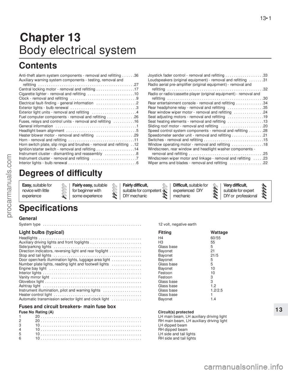
Chapter 13
Body electrical system
Anti-theft alarm system components - removal and refitting . . . . . .36
Auxiliary warning system components - testing, removal and
refitting . . . . . . . . . . . . . . . . . . . . . . . . . . . . . . . . . . . . . . . . . . . . .27
Central locking motor - removal and refitting . . . . . . . . . . . . . . . . . .17
Cigarette lighter - removal and refitting . . . . . . . . . . . . . . . . . . . . . .10
Clock - removal and refitting . . . . . . . . . . . . . . . . . . . . . . . . . . . . . . .9
Electrical fault-finding - general information . . . . . . . . . . . . . . . . . . .2
Exterior lights - bulb renewal . . . . . . . . . . . . . . . . . . . . . . . . . . . . . . .3
Exterior light units - removal and refitting . . . . . . . . . . . . . . . . . . . . .4
Fuel computer components - removal and refitting . . . . . . . . . . . . .26
Fuses, relays and control units - removal and refitting . . . . . . . . . .16
General information . . . . . . . . . . . . . . . . . . . . . . . . . . . . . . . . . . . . . .1
Headlight beam alignment . . . . . . . . . . . . . . . . . . . . . . . . . . . . . . . . .5
Heater blower motor - removal and refitting . . . . . . . . . . . . . . . . . .29
Horn - removal and refitting . . . . . . . . . . . . . . . . . . . . . . . . . . . . . . .11
Horn switch plate, slip rings and brushes - removal and refitting . .12
Ignition/starter switch - removal and refitting . . . . . . . . . . . . . . . . . .14
Instrument cluster - dismantling and reassembly . . . . . . . . . . . . . . .8
Instrument cluster - removal and refitting . . . . . . . . . . . . . . . . . . . . .7
Interior lights - bulb renewal . . . . . . . . . . . . . . . . . . . . . . . . . . . . . . . .6Joystick fader control - removal and refitting . . . . . . . . . . . . . . . . . .33
Loudspeakers (original equipment) - removal and refitting . . . . . . .31
Radio aerial pre-amplifier (original equipment) - removal and
refitting . . . . . . . . . . . . . . . . . . . . . . . . . . . . . . . . . . . . . . . . . . . . .32
Radio or radio/cassette player (original equipment) - removal and
refitting . . . . . . . . . . . . . . . . . . . . . . . . . . . . . . . . . . . . . . . . . . . . .30
Rear entertainment console - removal and refitting . . . . . . . . . . . . .34
Rear headphone relay - removal and refitting . . . . . . . . . . . . . . . . .35
Rear window wiper motor - removal and refitting . . . . . . . . . . . . . .24
Seat adjusting motors - removal and refitting . . . . . . . . . . . . . . . . .19
Seat heating elements - removal and refitting . . . . . . . . . . . . . . . . .13
Sliding roof motor - removal and refitting . . . . . . . . . . . . . . . . . . . .20
Speed control system components - removal and refitting . . . . . . .28
Speedometer sender unit - removal and refitting . . . . . . . . . . . . . . .21
Switches - removal and refitting . . . . . . . . . . . . . . . . . . . . . . . . . . . .15
Window operating motor - removal and refitting . . . . . . . . . . . . . . .18
Windscreen, rear window and headlight washer components -
removal and refitting . . . . . . . . . . . . . . . . . . . . . . . . . . . . . . . . . . .25
Windscreen wiper motor and linkage - removal and refitting . . . . .23
Wiper arms and blades - removal and refitting . . . . . . . . . . . . . . . .22
General
System type . . . . . . . . . . . . . . . . . . . . . . . . . . . . . . . . . . . . . . . . . . . . . . 12 volt, negative earth
Light bulbs (typical)Fitting Wattage
Headlights . . . . . . . . . . . . . . . . . . . . . . . . . . . . . . . . . . . . . . . . . . . . . . . . H4 60/55
Auxiliary driving lights and front foglights . . . . . . . . . . . . . . . . . . . . . . . . H3 55
Side/parking lights . . . . . . . . . . . . . . . . . . . . . . . . . . . . . . . . . . . . . . . . . Glass base 5
Direction indicators, reversing light and rear foglight . . . . . . . . . . . . . . . Bayonet 21
Stop and tail lights . . . . . . . . . . . . . . . . . . . . . . . . . . . . . . . . . . . . . . . . . Bayonet 21/5
Door open/kerb illumination lights, luggage area light . . . . . . . . . . . . . . Bayonet 5
Number plate lights, reading light and footwell lights . . . . . . . . . . . . . . Glass base 5
Engine bay light . . . . . . . . . . . . . . . . . . . . . . . . . . . . . . . . . . . . . . . . . . . Bayonet 10
Interior lights . . . . . . . . . . . . . . . . . . . . . . . . . . . . . . . . . . . . . . . . . . . . . . Festoon 10
Vanity mirror light . . . . . . . . . . . . . . . . . . . . . . . . . . . . . . . . . . . . . . . . . . Festoon 3
Glovebox light . . . . . . . . . . . . . . . . . . . . . . . . . . . . . . . . . . . . . . . . . . . . . Glass base 3
Ashtray light . . . . . . . . . . . . . . . . . . . . . . . . . . . . . . . . . . . . . . . . . . . . . . Glass base 1.2
Instrument illumination, pilot and warning lights . . . . . . . . . . . . . . . . . . Glass base 1.2/2.5
Heater control light . . . . . . . . . . . . . . . . . . . . . . . . . . . . . . . . . . . . . . . . . Glass base 1
Automatic transmission selector light and clock light . . . . . . . . . . . . . . Bayonet 1.4
Fuses and circuit breakers- main fuse box
Fuse No Rating (A) Circuit(s) protected
1 20 . . . . . . . . . . . . . . . . . . . . . . . . . . . . . . . . . . . . . . . . . . . . . . . LH main beam, LH auxiliary driving light
2 20 . . . . . . . . . . . . . . . . . . . . . . . . . . . . . . . . . . . . . . . . . . . . . . . RH main beam, LH auxiliary driving light
3 10 . . . . . . . . . . . . . . . . . . . . . . . . . . . . . . . . . . . . . . . . . . . . . . . LH dipped beam
4 10 . . . . . . . . . . . . . . . . . . . . . . . . . . . . . . . . . . . . . . . . . . . . . . . RH dipped beam
5 10 . . . . . . . . . . . . . . . . . . . . . . . . . . . . . . . . . . . . . . . . . . . . . . . LH side and tail lights
6 10 . . . . . . . . . . . . . . . . . . . . . . . . . . . . . . . . . . . . . . . . . . . . . . . RH side and tail lights
13•1
Easy,suitable for
novice with little
experienceFairly easy,suitable
for beginner with
some experienceFairly difficult,
suitable for competent
DIY mechanicDifficult,suitable for
experienced DIY
mechanicVery difficult,
suitable for expert
DIY or professional
Degrees of difficulty
Specifications Contents
13
procarmanuals.com
Page 185 of 255
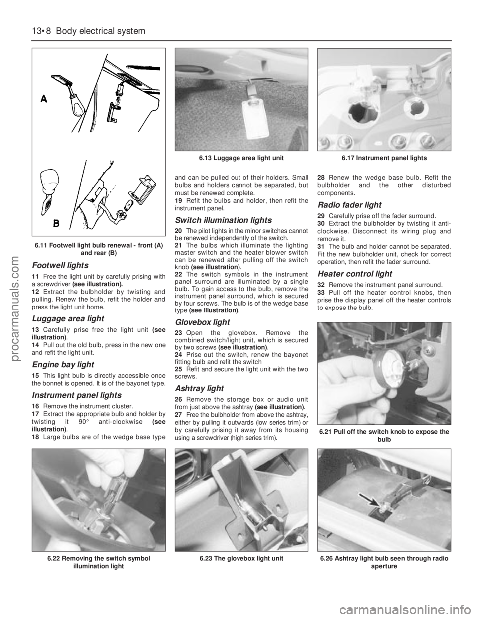
Footwell lights
11Free the light unit by carefully prising with
a screwdriver(see illustration).
12Extract the bulbholder by twisting and
pulling. Renew the bulb, refit the holder and
press the light unit home.
Luggage area light
13Carefully prise free the light unit (see
illustration).
14Pull out the old bulb, press in the new one
and refit the light unit.
Engine bay light
15This light bulb is directly accessible once
the bonnet is opened. It is of the bayonet type.
Instrument panel lights
16Remove the instrument cluster.
17Extract the appropriate bulb and holder by
twisting it 90°anti-clockwise (see
illustration).
18Large bulbs are of the wedge base typeand can be pulled out of their holders. Small
bulbs and holders cannot be separated, but
must be renewed complete.
19Refit the bulbs and holder, then refit the
instrument panel.
Switch illumination lights
20The pilot lights in the minor switches cannot
be renewed independently of the switch.
21The bulbs which illuminate the lighting
master switch and the heater blower switch
can be renewed after pulling off the switch
knob (see illustration).
22The switch symbols in the instrument
panel surround are illuminated by a single
bulb. To gain access to the bulb, remove the
instrument panel surround, which is secured
by four screws. The bulb is of the wedge base
type (see illustration).
Glovebox light
23Open the glovebox. Remove the
combined switch/light unit, which is secured
by two screws (see illustration).
24Prise out the switch, renew the bayonet
fitting bulb and refit the switch
25Refit and secure the light unit with the two
screws.
Ashtray light
26Remove the storage box or audio unit
from just above the ashtray (see illustration).
27Free the bulbholder from above the ashtray,
either by pulling it outwards (low series trim) or
by carefully prising it away from its housing
using a screwdriver (high series trim).28Renew the wedge base bulb. Refit the
bulbholder and the other disturbed
components.
Radio fader light
29Carefully prise off the fader surround.
30Extract the bulbholder by twisting it anti-
clockwise. Disconnect its wiring plug and
remove it.
31The bulb and holder cannot be separated.
Fit the new bulbholder unit, check for correct
operation, then refit the fader surround.
Heater control light
32Remove the instrument panel surround.
33Pull off the heater control knobs, then
prise the display panel off the heater controls
to expose the bulb.
13•8Body electrical system
6.21 Pull off the switch knob to expose the
bulb
6.26 Ashtray light bulb seen through radio
aperture6.22 Removing the switch symbol
illumination light6.23 The glovebox light unit
6.13 Luggage area light unit6.17 Instrument panel lights
6.11 Footwell light bulb renewal - front (A)
and rear (B)
procarmanuals.com
Page 186 of 255
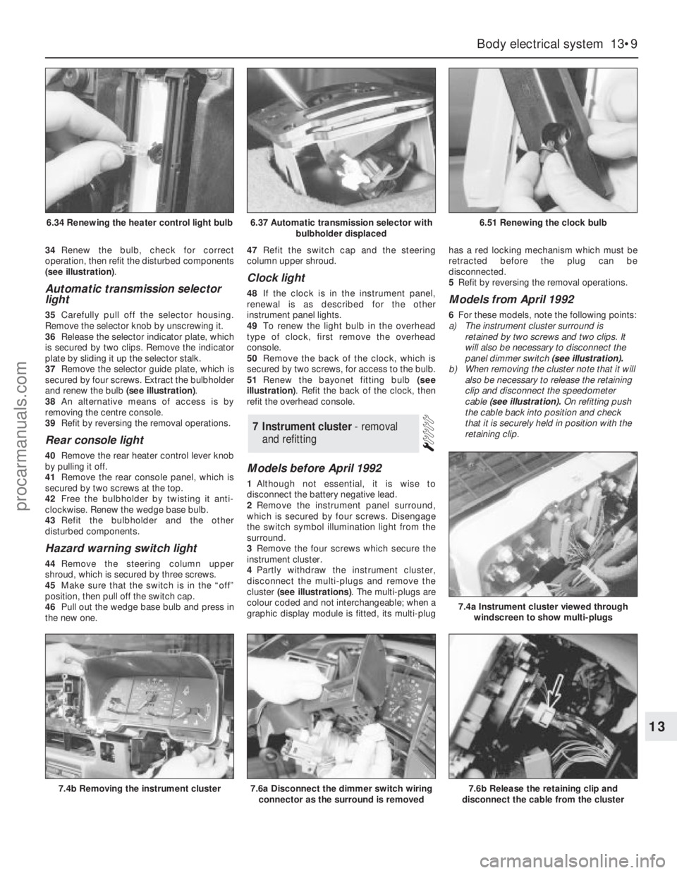
34Renew the bulb, check for correct
operation, then refit the disturbed components
(see illustration).
Automatic transmission selector
light
35Carefully pull off the selector housing.
Remove the selector knob by unscrewing it.
36Release the selector indicator plate, which
is secured by two clips. Remove the indicator
plate by sliding it up the selector stalk.
37Remove the selector guide plate, which is
secured by four screws. Extract the bulbholder
and renew the bulb (see illustration).
38An alternative means of access is by
removing the centre console.
39Refit by reversing the removal operations.
Rear console light
40Remove the rear heater control lever knob
by pulling it off.
41Remove the rear console panel, which is
secured by two screws at the top.
42Free the bulbholder by twisting it anti-
clockwise. Renew the wedge base bulb.
43Refit the bulbholder and the other
disturbed components.
Hazard warning switch light
44Remove the steering column upper
shroud, which is secured by three screws.
45Make sure that the switch is in the “off”
position, then pull off the switch cap.
46Pull out the wedge base bulb and press in
the new one.47Refit the switch cap and the steering
column upper shroud.
Clock light
48If the clock is in the instrument panel,
renewal is as described for the other
instrument panel lights.
49To renew the light bulb in the overhead
type of clock, first remove the overhead
console.
50Remove the back of the clock, which is
secured by two screws, for access to the bulb.
51Renew the bayonet fitting bulb (see
illustration). Refit the back of the clock, then
refit the overhead console.
Models before April 1992
1Although not essential, it is wise to
disconnect the battery negative lead.
2Remove the instrument panel surround,
which is secured by four screws. Disengage
the switch symbol illumination light from the
surround.
3Remove the four screws which secure the
instrument cluster.
4Partly withdraw the instrument cluster,
disconnect the multi-plugs and remove the
cluster (see illustrations). The multi-plugs are
colour coded and not interchangeable; when a
graphic display module is fitted, its multi-plughas a red locking mechanism which must be
retracted before the plug can be
disconnected.
5Refit by reversing the removal operations.
Models from April 1992
6For these models, note the following points:
a)The instrument cluster surround is
retained by two screws and two clips. It
will also be necessary to disconnect the
panel dimmer switch (see illustration).
b)When removing the cluster note that it will
also be necessary to release the retaining
clip and disconnect the speedometer
cable (see illustration).On refitting push
the cable back into position and check
that it is securely held in position with the
retaining clip.
7Instrument cluster - removal
and refitting
Body electrical system 13•9
13
6.37 Automatic transmission selector with
bulbholder displaced6.51 Renewing the clock bulb
7.4b Removing the instrument cluster7.6a Disconnect the dimmer switch wiring
connector as the surround is removed7.6b Release the retaining clip and
disconnect the cable from the cluster
7.4a Instrument cluster viewed through
windscreen to show multi-plugs
6.34 Renewing the heater control light bulb
procarmanuals.com