1985 FORD GRANADA ground clearance
[x] Cancel search: ground clearancePage 11 of 255
1Firmly apply the handbrake, then jack up the
front and rear of the car and support it
securely on axle stands (see “Jacking”).
2For a quick check, the front brake disc pads
can be inspected without removing the front
wheels, using a mirror and a torch through the
aperture in the rear face of the caliper. If any
one pad is worn down to the minimum
specified, all four pads (on both front wheels)
must be renewed.
3It is necessary to remove the rear wheels in
order to inspect the rear pads. The pads can
be viewed through the top of the caliper after
removing the spring clip. If any one pad is
worn down to the minimum specified, all four
pads (on both rear wheels) must be renewed.
4For a comprehensive check, the brake pads
should be removed and cleaned. The
operation of the caliper can then also be
checked, and the condition of the brake discs
can be fully examined on both sides. Refer to
Chapter 10 for further information.
5At the same interval, check the function of
the brake fluid level warning light. Chock the
wheels, release the handbrake and switch on
the ignition. Unscrew and raise the brake fluid
reservoir cap whilst an assistant observes the
warning light: it should come on as the level
sensor is withdrawn from the fluid. Refit the
cap.
6On completion, refit the wheels and lower
the car to the ground.
1Visually inspect the engine joint faces,
gaskets and seals for any signs of water or oil
leaks. Pay particular attention to the areas
around the rocker cover, cylinder head, oil
filter and sump joint faces. Bear in mind that
over a period of time some very slight seepage
from these areas is to be expected but what
you are really looking for is any indication of a
serious leak. Should a leak be found, renew
the offending gasket or oil seal by referring to
the appropriate Chapter(s) in this manual.
2Similarly, check the transmission for oil
leaks, and investigate and rectify and
problems found.
3Check the security and condition of all the
engine related pipes and hoses. Ensure that all
cable-ties or securing clips are in place and in
good condition. Clips which are broken or
missing can lead to chafing of the hoses,
pipes or wiring which could cause more
serious problems in the future.
4Carefully check the condition of all coolant,
fuel and brake hoses. Renew any hose which
is cracked, swollen or deteriorated. Cracks will
show up better if the hose is squeezed. Pay
close attention to the hose clips that secure
the hoses to the system components. Hoseclips can pinch and puncture hoses, resulting
in leaks. If wire type hose clips are used, it
may be a good idea to replace them with
screw-type clips.
5With the vehicle raised, inspect the fuel tank
and filler neck for punctures, cracks and other
damage. The connection between the filler neck
and tank is especially critical. Sometimes a
rubber filler neck or connecting hose will leak due
to loose retaining clamps or deteriorated rubber.
6Similarly, inspect all brake hoses and metal
pipes. If any damage or deterioration is
discovered, do not drive the vehicle until the
necessary repair work has been carried out.
Renew any damaged sections of hose or pipe.
7Carefully check all rubber hoses and metal
fuel lines leading away from the petrol tank.
Check for loose connections, deteriorated
hoses, crimped lines and other damage. Pay
particular attention to the vent pipes and
hoses which often loop up around the filler
neck and can become blocked or crimped.
Follow the lines to the front of the vehicle
carefully inspecting them all the way. Renew
damaged sections as necessary.
8From within the engine compartment, check
the security of all fuel hose attachments and
pipe unions, and inspect the fuel hoses and
vacuum hoses for kinks, chafing and
deterioration.
9Where applicable, check the condition of
the oil cooler hoses and pipes.
10Check the condition of all exposed wiring
harnesses.
11Also check the engine and transmission
components for signs of fluid leaks.
Periodically check the belts for fraying or
other damage. If evident, renew the belt.
If the belts become dirty, wipe them with a
damp cloth using a little detergent only.
Check the tightness of the anchor bolts and
if they are ever disconnected, make quite sure
that the original sequence of fitting of washers,
bushes and anchor plates is retained.With the vehicle raised on a hoist or
supported on axle stands (see “Jacking”),
check the exhaust system for signs of leaks,
corrosion or damage and check the rubber
mountings for condition and security. Where
damage or corrosion are evident, renew the
system complete or in sections, as applicable,
using the information given in Chapter 4.
With the wheels on the ground, slacken
each wheel nut by a quarter turn, then
retighten it immediately to the specified
torque.
Remove and clean the oil filler cap of any
sludge build-up using paraffin.
Inspect the vent hose for blockage or
damage. A blocked hose can cause a build-up
of crankcase pressure, which in turn can
cause oil leaks.
An accurate tachometer (rev. counter) will
be needed to adjust the idle speed. The
engine must be at operating temperature, the
air cleaner element must be clean and the
vacuum hoses fitted, and the engine valve
clearances must be correct. The ignition
system must also be in good condition.
Connect the tachometer to the engine as
instructed by the manufacturers. Start the
engine and allow it to idle. Read the speed
from the tachometer and compare it with the
value in the Specifications of Chapter 4
(Pierburg 2V carburettor).
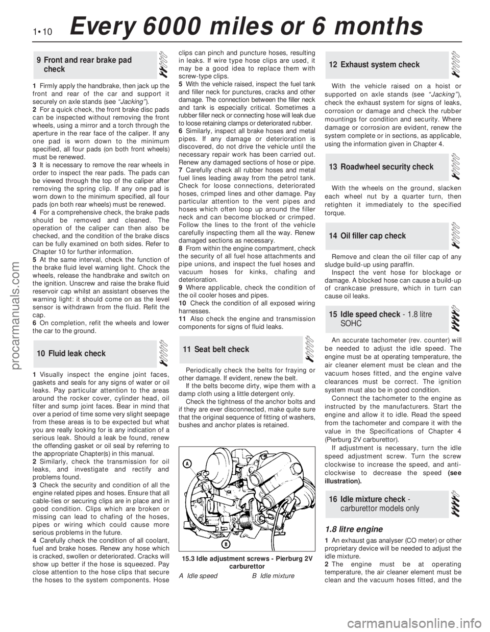
If adjustment is necessary, turn the idle
speed adjustment screw. Turn the screw
clockwise to increase the speed, and anti-
clockwise to decrease the speed (see
illustration).
1.8 litre engine
1An exhaust gas analyser (CO meter) or other
proprietary device will be needed to adjust the
idle mixture.
2The engine must be at operating
temperature, the air cleaner element must be
clean and the vacuum hoses fitted, and the
16Idle mixture check -
carburettor models only
15Idle speed check - 1.8 litre
SOHC
14Oil filler cap check
13Roadwheel security check
12Exhaust system check
11Seat belt check10Fluid leak check
9Front and rear brake pad
check
1•10Every 6000 miles or 6 months
15.3 Idle adjustment screws - Pierburg 2V
carburettor
A Idle speedB Idle mixture
procarmanuals.com
Page 12 of 255
engine valve clearances must be correct. The
ignition system must also be in good
condition.
3Mixture adjustment is not usual on a routine
basis. If the CO level is incorrect, proceed as
follows.
4Connect the exhaust gas analyser as
instructed by the manufacturers.
5Raise the engine speed to 3000 rpm
approximately and hold it at this speed for
30 seconds, then allow it to idle. Repeat this
procedure every 60 seconds until adjustment
is complete.6Read the CO level when it has stabilised
after the 3000 rpm burst. The desired level is
given in the Specifications of Chapter 4
(Pierburg 2V carburettor).
7If the idle mixture needs adjustment, turn
the mixture adjusting screw. The screw may
be covered by a tamperproof plug.
8Recheck the idle speed after adjusting the
mixture.
9Stop the engine and disconnect the test
gear. 10Fit a new tamperproof plug to the mixture
adjusting screw if required.
2.0 litre SOHC engine
11If mixture adjustment is required, proceed
as described for the 1.8 litre engine above.
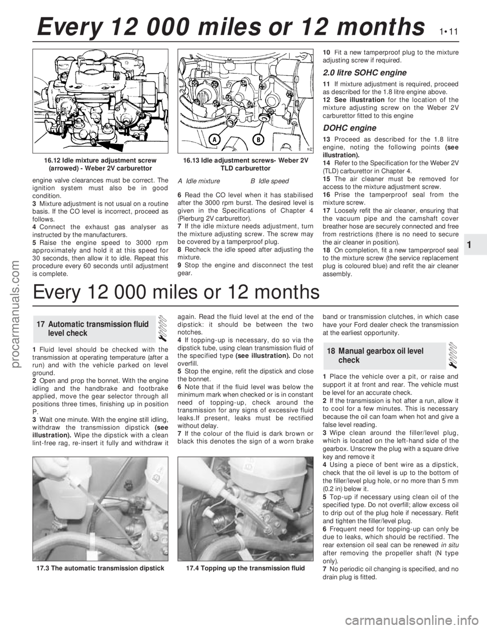
12See illustrationfor the location of the
mixture adjusting screw on the Weber 2V
carburettor fitted to this engine
DOHC engine
13Proceed as described for the 1.8 litre
engine, noting the following points (see
illustration).
14Refer to the Specification for the Weber 2V
(TLD) carburettor in Chapter 4.
15The air cleaner must be removed for
access to the mixture adjustment screw.
16Prise the tamperproof seal from the
mixture screw.
17Loosely refit the air cleaner, ensuring that
the vacuum pipe and the camshaft cover
breather hose are securely connected and free
from restrictions (there is no need to secure
the air cleaner in position).
18On completion, fit a new tamperproof seal
to the mixture screw (the service replacement
plug is coloured blue) and refit the air cleaner
assembly.
1Fluid level should be checked with the
transmission at operating temperature (after a
run) and with the vehicle parked on level
ground.
2Open and prop the bonnet. With the engine
idling and the handbrake and footbrake
applied, move the gear selector through all
positions three times, finishing up in position
P.
3Wait one minute. With the engine still idling,
withdraw the transmission dipstick (see
illustration).Wipe the dipstick with a clean
lint-free rag, re-insert it fully and withdraw itagain. Read the fluid level at the end of the
dipstick: it should be between the two
notches.
4If topping-up is necessary, do so via the
dipstick tube, using clean transmission fluid of
the specified type (see illustration).Do not
overfill.
5Stop the engine, refit the dipstick and close
the bonnet.
6Note that if the fluid level was below the
minimum mark when checked or is in constant
need oftopping-up, check around the
transmission for any signs of excessive fluid
leaks.If present, leaks must be rectified
without delay.
7If the colour of the fluid is dark brown or
black this denotes the sign of a worn brakeband or transmission clutches, in which case
have your Ford dealer check the transmission
at the earliest opportunity.
1Place the vehicle over a pit, or raise and
support it at front and rear. The vehicle must
be level for an accurate check.
2If the transmission is hot after a run, allow it
to cool for a few minutes. This is necessary
because the oil can foam when hot and give a
false level reading.
3Wipe clean around the filler/level plug,
which is located on the left-hand side of the
gearbox. Unscrew the plug with a square drive
key and remove it
4Using a piece of bent wire as a dipstick,
check that the oil level is up to the bottom of
the filler/level plug hole, or no more than 5 mm
(0.2 in) below it.
5Top-up if necessary using clean oil of the
specified type. Do not overfill; allow excess oil
to drip out of the plug hole if necessary. Refit
and tighten the filler/level plug.
6Frequent need for topping-up can only be
due to leaks, which should be rectified. The
rear extension oil seal can be renewedin situ
after removing the propeller shaft (N type
only).
7No periodic oil changing is specified, and no
drain plug is fitted.
18Manual gearbox oil level
check
17Automatic transmission fluid
level check
1•11
1
Every 12 000 miles or 12 months
16.13 Idle adjustment screws- Weber 2V
TLD carburettor
A Idle mixtureB Idle speed
16.12 Idle mixture adjustment screw
(arrowed) - Weber 2V carburettor
17.4 Topping up the transmission fluid17.3 The automatic transmission dipstick
Every 12 000 miles or 12 months
procarmanuals.com
Page 35 of 255
mountings to the front crossmember. Recover
the washers.
3Raise the engine with a hoist or a suitable
protected jack until the mountings are free,
then remove them.
4Fit the new mountings and lower the engine
onto them.
5Fit the nuts and washers and tighten the
nuts.
6Lower the vehicle.
Carburettor models
The crankcase ventilation system consists
of the special oil filter cap (containing a steel
wool filter) and an oil separator and vent valve
on the left-hand side of the engine. This is
connected by hose to the inlet manifold. The
system operates according to the vacuum in
the inlet manifold. Air is drawn through the
filler cap, through the crankcase, and then
together with piston blow-by gasses through
the oil separator and vent valve to the inlet
manifold. The blow-by gases are then drawn
into the engine together with the fuel/air
mixture. Refer to Chapter 1 for maintenance of
the system.
Fuel-injection models
This system is closed, consisting of an oilseparator on the left-hand side of the engine
and a hose connecting it to the inlet air
trunking. Because the trunking is not subject
to manifold vacuum, no vent valve is needed.
1With the engine completely stripped, clean
all the components and examine them for
wear. Each part should be checked, and
where necessary renewed or renovated as
described in the following Sections. Renew
main and big end shell bearings as a matter of
course, unless you know that they have had
little wear and are in perfect condition.
2If in doubt as to whether to renew a
component which is still just serviceable,
consider the time and effort which will be
incurred should it fail at an early date.
Obviously the age and expected life of the
vehicle must influence the standards applied.
3Gaskets, oil seals and O-rings must all be
renewed as a matter of routine. Flywheel and
cylinder head bolts must be renewed because
of the high stresses to which they are
subjected.
4Take the opportunity to renew the engine
core plugs while they are easily accessible.
Knock out the old plugs with a hammer and
chisel or punch. Clean the plug seats, smear
the new plugs with sealant and tap them
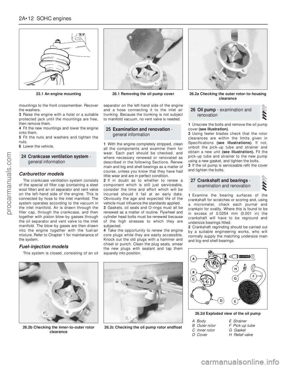
squarely into position.1Unscrew the bolts and remove the oil pump
cover (see illustration).
2Using feeler blades check that the rotor
clearances are within the limits given in
Specifications (see illustrations). If not,
unbolt the pick-up tube and strainer and
obtain a new unit (see illustration).Fit the
pick-up tube and strainer to the new pump
using a new gasket, and tighten the bolts.
3If the oil pump is serviceable refit the cover
and tighten the bolts.
1Examine the bearing surfaces of the
crankshaft for scratches or scoring and, using
a micrometer, check each journal and
crankpin for ovality. Where this is found to be
in excess of 0.0254 mm (0.001 in) the
crankshaft will have to be reground and
undersize bearings fitted.
2Crankshaft regrinding should be carried out
by a suitable engineering works, who will
normally supply the matching undersize main
and big-end shell bearings.
27Crankshaft and bearings -
examination and renovation
26Oil pump - examination and
renovation
25Examination and renovation -
general information
24Crankcase ventilation system -
general information
2A•12SOHCengines
23.1 An engine mounting
26.2b Checking the inner-to-outer rotor
clearance26.2c Checking the oil pump rotor endfloat
26.2d Exploded view of the oil pump
A Body
B Outer rotor
C Inner rotor
D CoverE Strainer
F Pick-up tube
G Gasket
H Relief valve
26.1 Removing the oil pump cover26.2a Checking the outer rotor-to-housing
clearance
procarmanuals.com
Page 36 of 255
3Note that undersize bearings may already
have been fitted, either in production or by a
previous repairer. Check the markings on the
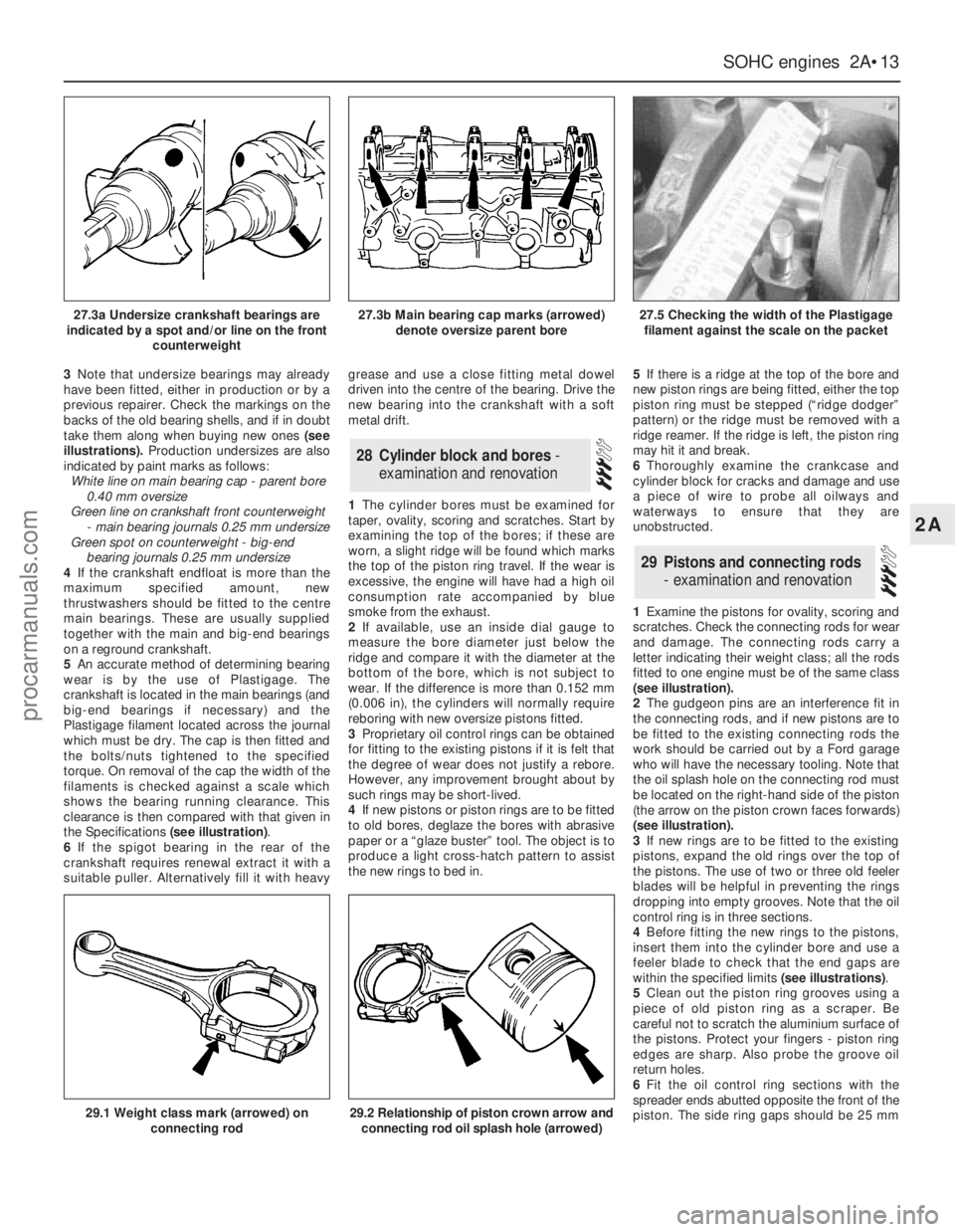
backs of the old bearing shells, and if in doubt
take them along when buying new ones(see
illustrations).Production undersizes are also
indicated by paint marks as follows:
White line on main bearing cap - parent bore
0.40 mm oversize
Green line on crankshaft front counterweight
- main bearing journals 0.25 mm undersize
Green spot on counterweight - big-end
bearing journals 0.25 mm undersize
4If the crankshaft endfloat is more than the
maximum specified amount, new
thrustwashers should be fitted to the centre
main bearings. These are usually supplied
together with the main and big-end bearings
on a reground crankshaft.
5An accurate method of determining bearing
wear is by the use of Plastigage. The
crankshaft is located in the main bearings (and
big-end bearings if necessary) and the
Plastigage filament located across the journal
which must be dry. The cap is then fitted and
the bolts/nuts tightened to the specified
torque. On removal of the cap the width of the
filaments is checked against a scale which
shows the bearing running clearance. This
clearance is then compared with that given in
the Specifications (see illustration).
6If the spigot bearing in the rear of the
crankshaft requires renewal extract it with a
suitable puller. Alternatively fill it with heavygrease and use a close fitting metal dowel
driven into the centre of the bearing. Drive the
new bearing into the crankshaft with a soft
metal drift.
1The cylinder bores must be examined for
taper, ovality, scoring and scratches. Start by
examining the top of the bores; if these are
worn, a slight ridge will be found which marks
the top of the piston ring travel. If the wear is
excessive, the engine will have had a high oil
consumption rate accompanied by blue
smoke from the exhaust.
2If available, use an inside dial gauge to
measure the bore diameter just below the
ridge and compare it with the diameter at the
bottom of the bore, which is not subject to
wear. If the difference is more than 0.152 mm
(0.006 in), the cylinders will normally require
reboring with new oversize pistons fitted.
3Proprietary oil control rings can be obtained
for fitting to the existing pistons if it is felt that
the degree of wear does not justify a rebore.
However, any improvement brought about by
such rings may be short-lived.
4If new pistons or piston rings are to be fitted
to old bores, deglaze the bores with abrasive
paper or a “glaze buster” tool. The object is to
produce a light cross-hatch pattern to assist
the new rings to bed in. 5If there is a ridge at the top of the bore and
new piston rings are being fitted, either the top
piston ring must be stepped (“ridge dodger”
pattern) or the ridge must be removed with a
ridge reamer. If the ridge is left, the piston ring
may hit it and break.
6Thoroughly examine the crankcase and
cylinder block for cracks and damage and use
a piece of wire to probe all oilways and
waterways to ensure that they are
unobstructed.
1Examine the pistons for ovality, scoring and
scratches. Check the connecting rods for wear
and damage. The connecting rods carry a
letter indicating their weight class; all the rods
fitted to one engine must be of the same class
(see illustration).
2The gudgeon pins are an interference fit in
the connecting rods, and if new pistons are to
be fitted to the existing connecting rods the
work should be carried out by a Ford garage
who will have the necessary tooling. Note that
the oil splash hole on the connecting rod must
be located on the right-hand side of the piston
(the arrow on the piston crown faces forwards)
(see illustration).
3If new rings are to be fitted to the existing
pistons, expand the old rings over the top of
the pistons. The use of two or three old feeler
blades will be helpful in preventing the rings
dropping into empty grooves. Note that the oil
control ring is in three sections.
4Before fitting the new rings to the pistons,
insert them into the cylinder bore and use a
feeler blade to check that the end gaps are
within the specified limits (see illustrations).
5Clean out the piston ring grooves using a
piece of old piston ring as a scraper. Be
careful not to scratch the aluminium surface of
the pistons. Protect your fingers - piston ring
edges are sharp. Also probe the groove oil
return holes.
6Fit the oil control ring sections with the
spreader ends abutted opposite the front of the
piston. The side ring gaps should be 25 mm
29Pistons and connecting rods
- examination and renovation
28Cylinder block and bores -
examination and renovation
SOHCengines 2A•13
2A
27.3a Undersize crankshaft bearings are
indicated by a spot and/or line on the front
counterweight27.3b Main bearing cap marks (arrowed)
denote oversize parent bore27.5 Checking the width of the Plastigage
filament against the scale on the packet
29.1 Weight class mark (arrowed) on
connecting rod29.2 Relationship of piston crown arrow and
connecting rod oil splash hole (arrowed)
procarmanuals.com
Page 248 of 255
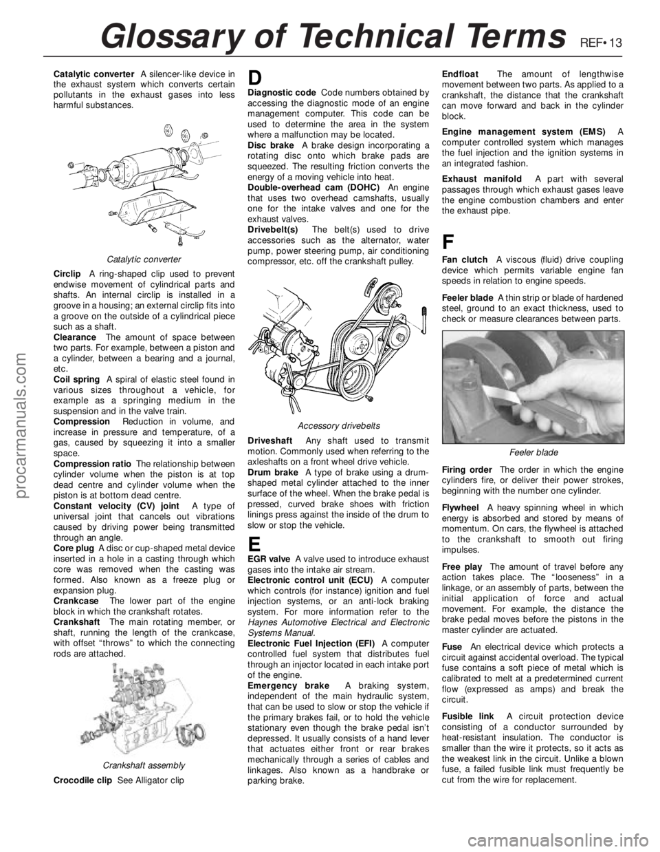
REF•13Glossary of Technical Terms
Catalytic converterA silencer-like device in
the exhaust system which converts certain
pollutants in the exhaust gases into less
harmful substances.
CirclipA ring-shaped clip used to prevent
endwise movement of cylindrical parts and
shafts. An internal circlip is installed in a
groove in a housing; an external circlip fits into
a groove on the outside of a cylindrical piece
such as a shaft.
ClearanceThe amount of space between
two parts. For example, between a piston and
a cylinder, between a bearing and a journal,
etc.
Coil springA spiral of elastic steel found in
various sizes throughout a vehicle, for
example as a springing medium in the
suspension and in the valve train.
CompressionReduction in volume, and
increase in pressure and temperature, of a
gas, caused by squeezing it into a smaller
space.
Compression ratioThe relationship between
cylinder volume when the piston is at top
dead centre and cylinder volume when the
piston is at bottom dead centre.
Constant velocity (CV) jointA type of
universal joint that cancels out vibrations
caused by driving power being transmitted
through an angle.
Core plugA disc or cup-shaped metal device
inserted in a hole in a casting through which
core was removed when the casting was
formed. Also known as a freeze plug or
expansion plug.
CrankcaseThe lower part of the engine
block in which the crankshaft rotates.
CrankshaftThe main rotating member, or
shaft, running the length of the crankcase,
with offset “throws” to which the connecting
rods are attached.
Crocodile clipSee Alligator clipDDiagnostic codeCode numbers obtained by
accessing the diagnostic mode of an engine
management computer. This code can be
used to determine the area in the system
where a malfunction may be located.
Disc brakeA brake design incorporating a
rotating disc onto which brake pads are
squeezed. The resulting friction converts the
energy of a moving vehicle into heat.
Double-overhead cam (DOHC)An engine
that uses two overhead camshafts, usually
one for the intake valves and one for the
exhaust valves.
Drivebelt(s)The belt(s) used to drive
accessories such as the alternator, water
pump, power steering pump, air conditioning
compressor, etc. off the crankshaft pulley.
DriveshaftAny shaft used to transmit
motion. Commonly used when referring to the
axleshafts on a front wheel drive vehicle.
Drum brakeA type of brake using a drum-
shaped metal cylinder attached to the inner
surface of the wheel. When the brake pedal is
pressed, curved brake shoes with friction
linings press against the inside of the drum to
slow or stop the vehicle.
EEGR valveA valve used to introduce exhaust
gases into the intake air stream.
Electronic control unit (ECU)A computer
which controls (for instance) ignition and fuel
injection systems, or an anti-lock braking
system. For more information refer to the
Haynes Automotive Electrical and Electronic
Systems Manual.
Electronic Fuel Injection (EFI)A computer
controlled fuel system that distributes fuel
through an injector located in each intake port
of the engine.
Emergency brakeA braking system,
independent of the main hydraulic system,
that can be used to slow or stop the vehicle if
the primary brakes fail, or to hold the vehicle
stationary even though the brake pedal isn’t
depressed. It usually consists of a hand lever
that actuates either front or rear brakes
mechanically through a series of cables and
linkages. Also known as a handbrake or
parking brake.EndfloatThe amount of lengthwise
movement between two parts. As applied to a
crankshaft, the distance that the crankshaft
can move forward and back in the cylinder
block.
Engine management system (EMS)A
computer controlled system which manages
the fuel injection and the ignition systems in
an integrated fashion.
Exhaust manifoldA part with several
passages through which exhaust gases leave
the engine combustion chambers and enter
the exhaust pipe.
F
Fan clutchA viscous (fluid) drive coupling
device which permits variable engine fan
speeds in relation to engine speeds.
Feeler bladeA thin strip or blade of hardened
steel, ground to an exact thickness, used to
check or measure clearances between parts.
Firing orderThe order in which the engine
cylinders fire, or deliver their power strokes,
beginning with the number one cylinder.
Flywheel A heavy spinning wheel in which
energy is absorbed and stored by means of
momentum. On cars, the flywheel is attached
to the crankshaft to smooth out firing
impulses.
Free playThe amount of travel before any
action takes place. The “looseness” in a
linkage, or an assembly of parts, between the
initial application of force and actual
movement. For example, the distance the
brake pedal moves before the pistons in the
master cylinder are actuated.
FuseAn electrical device which protects a
circuit against accidental overload. The typical
fuse contains a soft piece of metal which is
calibrated to melt at a predetermined current
flow (expressed as amps) and break the
circuit.
Fusible linkA circuit protection device
consisting of a conductor surrounded by
heat-resistant insulation. The conductor is
smaller than the wire it protects, so it acts as
the weakest link in the circuit. Unlike a blown
fuse, a failed fusible link must frequently be
cut from the wire for replacement.Catalytic converter
Crankshaft assembly
Accessory drivebelts
Feeler blade
procarmanuals.com