1985 FORD GRANADA open bonnet
[x] Cancel search: open bonnetPage 7 of 255
1•6Maintenance Procedures
This Chapter is designed to help the home
mechanic maintain his/her vehicle for safety,
economy, long life and peak performance.
The Chapter contains a master maintenance
schedule, followed by Sections dealing
specifically with each task in the schedule.
Visual checks, adjustments, component
renewal and other helpful items are included.
Refer to the accompanying illustrations of the
engine compartment and the underside of the
vehicle for the locations of the various
components.
Servicing your vehicle in accordance with
the mileage/time maintenance schedule and
the following Sections will provide a planned
maintenance programme, which should result
in a long and reliable service life. This is a
comprehensive plan, so maintaining some
items but not others at the specified service
intervals, will not produce the same results.
As you service your vehicle, you will
discover that many of the procedures can -
and should - be grouped together, because of
the particular procedure being performed, or
because of the close proximity of two
otherwise-unrelated components to one
another. For example, if the vehicle is raised
for any reason, the exhaust can be inspected
at the same time as the suspension and
steering components.
The first step in this maintenanceprogramme is to prepare yourself before the
actual work begins. Read through all the
Sections relevant to the work to be carried out,
then make a list and gather together all the
parts and tools required. If a problem is
encountered, seek advice from a parts
specialist, or a dealer service department.
If, from the time the vehicle is new, the
routine maintenance schedule is followed
closely, and frequent checks are made of fluid
levels and high-wear items, as suggested
throughout this manual, the engine will be kept
in relatively good running condition, and the
need for additional work will be minimised.
It is possible that there will be times when
the engine is running poorly due to the lack of
regular maintenance. This is even more likely if
a used vehicle, which has not received regular
and frequent maintenance checks, is
purchased. In such cases, additional work
may need to be carried out, outside of the
regular maintenance intervals.
If engine wear is suspected, a compression
test will provide valuable information regarding
the overall performance of the main internal
components. Such a test can be used as a
basis to decide on the extent of the work to be
carried out. If, for example, a compression test
indicates serious internal engine wear,
conventional maintenance as described in this
Chapter will not greatly improve theperformance of the engine, and may prove a
waste of time and money, unless extensive
overhaul work is carried out first.
The following series of operations are those
most often required to improve the
performance of a generally poor-running
engine:
Primary operations
a)Clean, inspect and test the battery
(Section 6)
b)Check all the engine-related fluids
(Section 3).
c)Check the condition and tension of the
auxiliary drivebelt (Section 21).
d)Renew the spark plugs (Section 20).
e)Inspect the distributor cap, rotor arm and
HT leads - as applicable (Chapter 5).
f)Check the condition of the air cleaner filter
element, and renew if necessary (Section 38).
g)Renew the fuel filter (Section 41).
h)Check the condition of all hoses, and
check for fluid leaks (Section 10).
i)Check the idle speed and mixture settings
- as applicable (Chapter 4).
If the above operations do not prove fully
effective, carry out the following secondary
operations:
Secondary operations
a)Check the charging system (Chapter 5).
b)Check the ignition system (Chapter 5).
c)Check the fuel system (Chapter 4).
d)Renew the distributor cap and rotor arm -
as applicable (Chapter 5).
f)Renew the ignition HT leads - as
applicable (Chapter 5).
2Intensive maintenance
1Introduction
Engine oil
1Check the oil level as follows.
2With the vehicle parked on level ground,
and with the engine having been stopped for a
few minutes, open and prop the bonnet.
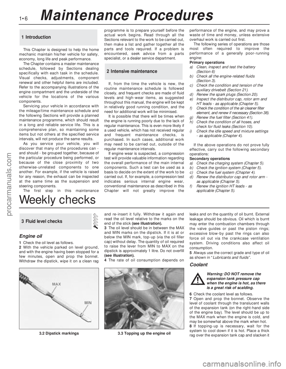
Withdraw the dipstick, wipe it on a clean ragand re-insert it fully. Withdraw it again and
read the oil level relative to the marks on the
end of the stick (see illustration).
3The oil level should be in between the MAX
and MIN marks on the dipstick. If it is at or
below the MIN mark, top-up (via the oil filler
cap) without delay. The quantity of oil required
to raise the lever from MIN to MAX on the
dipstick is approximately 1 litre. Do not overfill
(see illustration).
4The rate of oil consumption depends onleaks and on the quantity of oil burnt. External
leakage should be obvious. Oil which is burnt
may enter the combustion chambers through
the valve guides or past the piston rings;
excessive blow-by past the rings can also
force oil out via the crankcase ventilation
system. Driving conditions also affect oil
consumption.
5Always use the correct grade and type of oil
as shown in “Lubricants and fluids”.
Coolant
6Check the coolant level as follows.
7Open and prop the bonnet. Observe the
level of coolant through the translucent walls
of the expansion tank (on the right-hand side
of the engine bay). The level should be up to
the MAX mark when the engine is cold, and
may be somewhat above the mark when hot.
8If topping-up is necessary, wait for the
system to cool down if it is hot. Place a thick
rag over the expansion tank cap and slacken it
3Fluid level checks
3.2 Dipstick markings3.3 Topping up the engine oil
Warning: DO NOT remove the
expansion tank pressure cap
when the engine is hot, as there
is a great risk of scalding.
Weekly checks
procarmanuals.com
Page 8 of 255
to release any pressure. When pressure has
been released, carry on unscrewing the cap
and remove it.
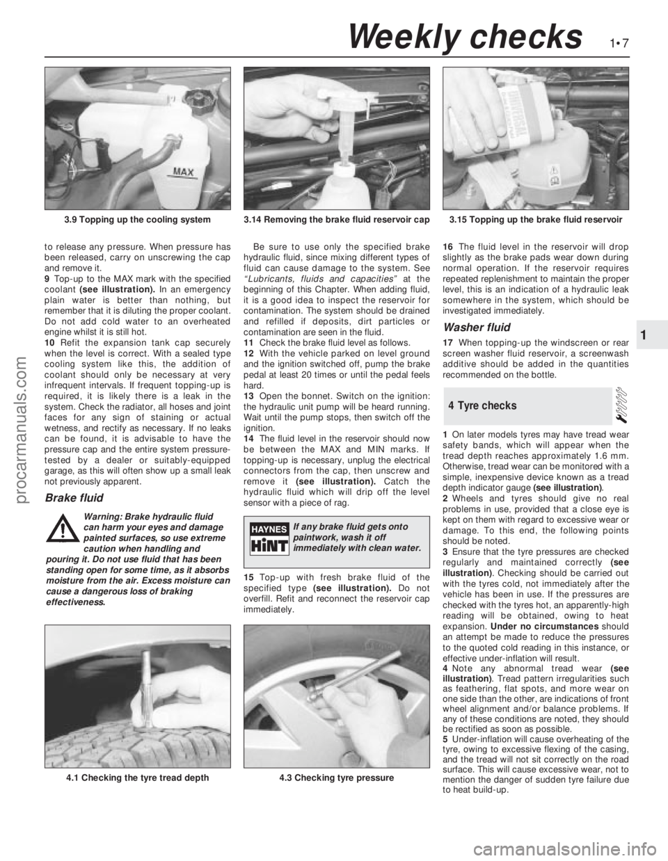
9Top-up to the MAX mark with the specified
coolant (see illustration).In an emergency
plain water is better than nothing, but
remember that it is diluting the proper coolant.
Do not add cold water to an overheated
engine whilst it is still hot.
10Refit the expansion tank cap securely
when the level is correct. With a sealed type
cooling system like this, the addition of
coolant should only be necessary at very
infrequent intervals. If frequent topping-up is
required, it is likely there is a leak in the
system. Check the radiator, all hoses and joint
faces for any sign of staining or actual
wetness, and rectify as necessary. If no leaks
can be found, it is advisable to have the
pressure cap and the entire system pressure-
tested by a dealer or suitably-equipped
garage, as this will often show up a small leak
not previously apparent.
Brake fluid
Be sure to use only the specified brake
hydraulic fluid, since mixing different types of
fluid can cause damage to the system. See
“Lubricants, fluids and capacities”at the
beginning of this Chapter. When adding fluid,
it is a good idea to inspect the reservoir for
contamination. The system should be drained
and refilled if deposits, dirt particles or
contamination are seen in the fluid.
11Check the brake fluid level as follows.
12With the vehicle parked on level ground
and the ignition switched off, pump the brake
pedal at least 20 times or until the pedal feels
hard.
13Open the bonnet. Switch on the ignition:
the hydraulic unit pump will be heard running.
Wait until the pump stops, then switch off the
ignition.
14The fluid level in the reservoir should now
be between the MAX and MIN marks. If
topping-up is necessary, unplug the electrical
connectors from the cap, then unscrew and
remove it (see illustration).Catch the
hydraulic fluid which will drip off the level
sensor with a piece of rag.
15Top-up with fresh brake fluid of the
specified type (see illustration).Do not
overfill. Refit and reconnect the reservoir cap
immediately.16The fluid level in the reservoir will drop
slightly as the brake pads wear down during
normal operation. If the reservoir requires
repeated replenishment to maintain the proper
level, this is an indication of a hydraulic leak
somewhere in the system, which should be
investigated immediately.
Washer fluid
17When topping-up the windscreen or rear
screen washer fluid reservoir, a screenwash
additive should be added in the quantities
recommended on the bottle.
1On later models tyres may have tread wear
safety bands, which will appear when the
tread depth reaches approximately 1.6 mm.
Otherwise, tread wear can be monitored with a
simple, inexpensive device known as a tread
depth indicator gauge (see illustration).
2Wheels and tyres should give no real
problems in use, provided that a close eye is
kept on them with regard to excessive wear or
damage. To this end, the following points
should be noted.
3Ensure that the tyre pressures are checked
regularly and maintained correctly (see
illustration). Checking should be carried out
with the tyres cold, not immediately after the
vehicle has been in use. If the pressures are
checked with the tyres hot, an apparently-high
reading will be obtained, owing to heat
expansion. Under no circumstancesshould
an attempt be made to reduce the pressures
to the quoted cold reading in this instance, or
effective under-inflation will result.
4Note any abnormal tread wear (see
illustration). Tread pattern irregularities such
as feathering, flat spots, and more wear on
one side than the other, are indications of front
wheel alignment and/or balance problems. If
any of these conditions are noted, they should
be rectified as soon as possible.
5Under-inflation will cause overheating of the
tyre, owing to excessive flexing of the casing,
and the tread will not sit correctly on the road
surface. This will cause excessive wear, not to
mention the danger of sudden tyre failure due
to heat build-up.
4Tyre checks
1•7
1
Weekly checks
3.14 Removing the brake fluid reservoir cap3.15 Topping up the brake fluid reservoir
4.1 Checking the tyre tread depth4.3 Checking tyre pressure
3.9 Topping up the cooling system
Warning: Brake hydraulic fluid
can harm your eyes and damage
painted surfaces, so use extreme
caution when handling and
pouring it. Do not use fluid that has been
standing open for some time, as it absorbs
moisture from the air. Excess moisture can
cause a dangerous loss of braking
effectiveness.If any brake fluid gets onto
paintwork, wash it off
immediately with clean water.
procarmanuals.com
Page 12 of 255
engine valve clearances must be correct. The
ignition system must also be in good
condition.
3Mixture adjustment is not usual on a routine
basis. If the CO level is incorrect, proceed as
follows.
4Connect the exhaust gas analyser as
instructed by the manufacturers.
5Raise the engine speed to 3000 rpm
approximately and hold it at this speed for
30 seconds, then allow it to idle. Repeat this
procedure every 60 seconds until adjustment
is complete.6Read the CO level when it has stabilised
after the 3000 rpm burst. The desired level is
given in the Specifications of Chapter 4
(Pierburg 2V carburettor).
7If the idle mixture needs adjustment, turn
the mixture adjusting screw. The screw may
be covered by a tamperproof plug.
8Recheck the idle speed after adjusting the
mixture.
9Stop the engine and disconnect the test
gear. 10Fit a new tamperproof plug to the mixture
adjusting screw if required.
2.0 litre SOHC engine
11If mixture adjustment is required, proceed
as described for the 1.8 litre engine above.
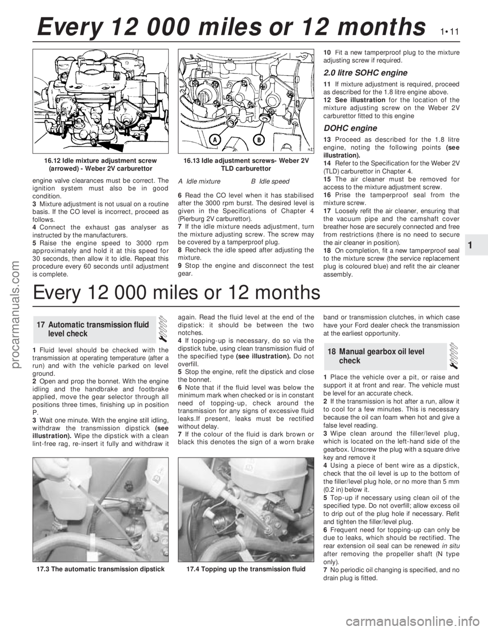
12See illustrationfor the location of the
mixture adjusting screw on the Weber 2V
carburettor fitted to this engine
DOHC engine
13Proceed as described for the 1.8 litre
engine, noting the following points (see
illustration).
14Refer to the Specification for the Weber 2V
(TLD) carburettor in Chapter 4.
15The air cleaner must be removed for
access to the mixture adjustment screw.
16Prise the tamperproof seal from the
mixture screw.
17Loosely refit the air cleaner, ensuring that
the vacuum pipe and the camshaft cover
breather hose are securely connected and free
from restrictions (there is no need to secure
the air cleaner in position).
18On completion, fit a new tamperproof seal
to the mixture screw (the service replacement
plug is coloured blue) and refit the air cleaner
assembly.
1Fluid level should be checked with the
transmission at operating temperature (after a
run) and with the vehicle parked on level
ground.
2Open and prop the bonnet. With the engine
idling and the handbrake and footbrake
applied, move the gear selector through all
positions three times, finishing up in position
P.
3Wait one minute. With the engine still idling,
withdraw the transmission dipstick (see
illustration).Wipe the dipstick with a clean
lint-free rag, re-insert it fully and withdraw itagain. Read the fluid level at the end of the
dipstick: it should be between the two
notches.
4If topping-up is necessary, do so via the
dipstick tube, using clean transmission fluid of
the specified type (see illustration).Do not
overfill.
5Stop the engine, refit the dipstick and close
the bonnet.
6Note that if the fluid level was below the
minimum mark when checked or is in constant
need oftopping-up, check around the
transmission for any signs of excessive fluid
leaks.If present, leaks must be rectified
without delay.
7If the colour of the fluid is dark brown or
black this denotes the sign of a worn brakeband or transmission clutches, in which case
have your Ford dealer check the transmission
at the earliest opportunity.
1Place the vehicle over a pit, or raise and
support it at front and rear. The vehicle must
be level for an accurate check.
2If the transmission is hot after a run, allow it
to cool for a few minutes. This is necessary
because the oil can foam when hot and give a
false level reading.
3Wipe clean around the filler/level plug,
which is located on the left-hand side of the
gearbox. Unscrew the plug with a square drive
key and remove it
4Using a piece of bent wire as a dipstick,
check that the oil level is up to the bottom of
the filler/level plug hole, or no more than 5 mm
(0.2 in) below it.
5Top-up if necessary using clean oil of the
specified type. Do not overfill; allow excess oil
to drip out of the plug hole if necessary. Refit
and tighten the filler/level plug.
6Frequent need for topping-up can only be
due to leaks, which should be rectified. The
rear extension oil seal can be renewedin situ
after removing the propeller shaft (N type
only).
7No periodic oil changing is specified, and no
drain plug is fitted.
18Manual gearbox oil level
check
17Automatic transmission fluid
level check
1•11
1
Every 12 000 miles or 12 months
16.13 Idle adjustment screws- Weber 2V
TLD carburettor
A Idle mixtureB Idle speed
16.12 Idle mixture adjustment screw
(arrowed) - Weber 2V carburettor
17.4 Topping up the transmission fluid17.3 The automatic transmission dipstick
Every 12 000 miles or 12 months
procarmanuals.com
Page 67 of 255
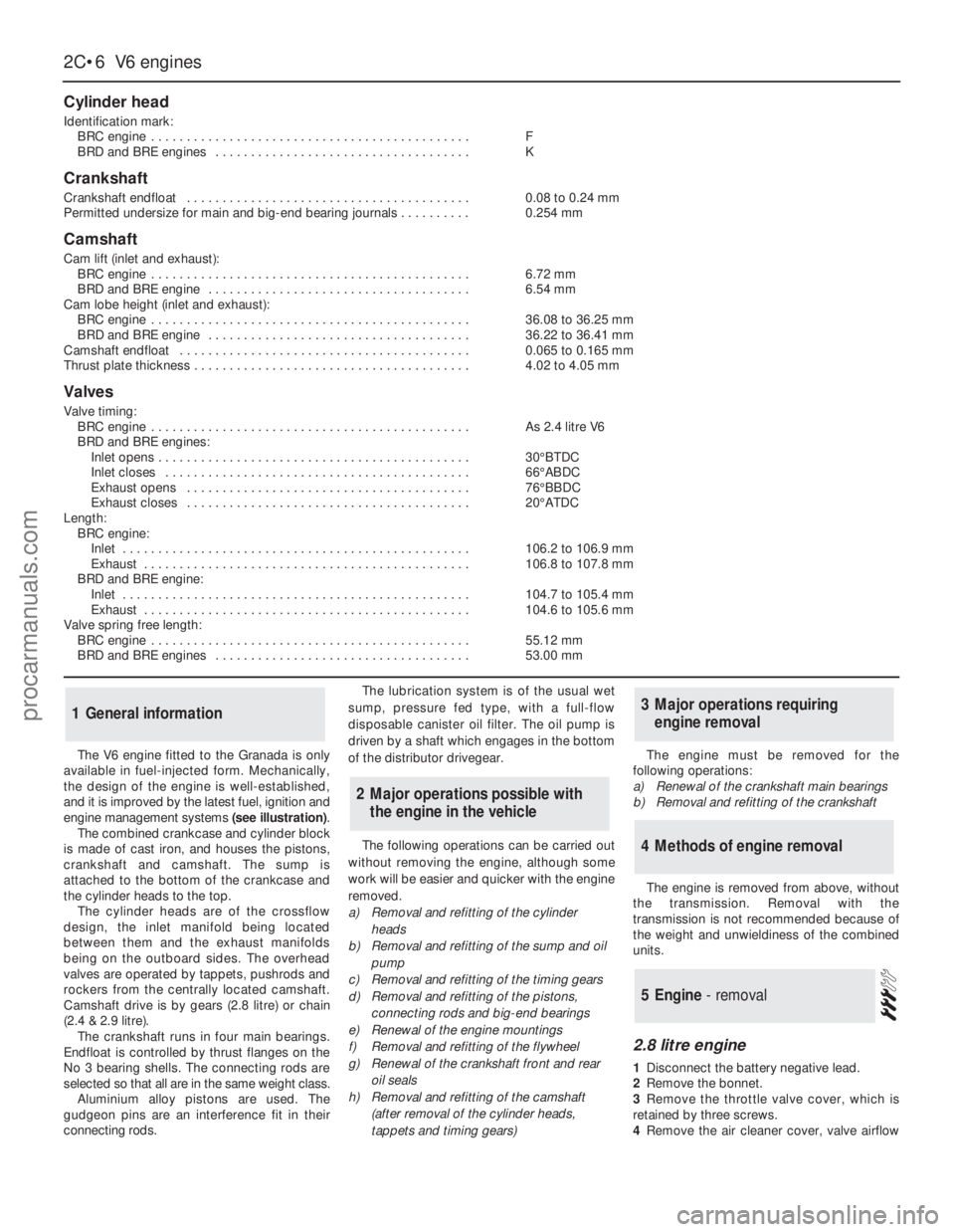
The V6 engine fitted to the Granada is only
available in fuel-injected form. Mechanically,
the design of the engine is well-established,
and it is improved by the latest fuel, ignition and
engine management systems (see illustration).
The combined crankcase and cylinder block
is made of cast iron, and houses the pistons,
crankshaft and camshaft. The sump is
attached to the bottom of the crankcase and
the cylinder heads to the top.
The cylinder heads are of the crossflow
design, the inlet manifold being located
between them and the exhaust manifolds
being on the outboard sides. The overhead
valves are operated by tappets, pushrods and
rockers from the centrally located camshaft.
Camshaft drive is by gears (2.8 litre) or chain
(2.4 & 2.9 litre).
The crankshaft runs in four main bearings.
Endfloat is controlled by thrust flanges on the
No 3 bearing shells. The connecting rods are
selected so that all are in the same weight class.
Aluminium alloy pistons are used. The
gudgeon pins are an interference fit in their
connecting rods.The lubrication system is of the usual wet
sump, pressure fed type, with a full-flow
disposable canister oil filter. The oil pump is
driven by a shaft which engages in the bottom
of the distributor drivegear.
The following operations can be carried out
without removing the engine, although some
work will be easier and quicker with the engine
removed.
a)Removal and refitting of the cylinder
heads
b)Removal and refitting of the sump and oil
pump
c)Removal and refitting of the timing gears
d)Removal and refitting of the pistons,
connecting rods and big-end bearings
e)Renewal of the engine mountings
f)Removal and refitting of the flywheel
g)Renewal of the crankshaft front and rear
oil seals
h)Removal and refitting of the camshaft
(after removal of the cylinder heads,
tappets and timing gears)The engine must be removed for the
following operations:
a)Renewal of the crankshaft main bearings
b)Removal and refitting of the crankshaft
The engine is removed from above, without
the transmission. Removal with the
transmission is not recommended because of
the weight and unwieldiness of the combined
units.
2.8 litre engine
1Disconnect the battery negative lead.
2Remove the bonnet.
3Remove the throttle valve cover, which is
retained by three screws.
4Remove the air cleaner cover, valve airflow
5Engine - removal
4Methods of engine removal
3Major operations requiring
engine removal
2Major operations possible with
the engine in the vehicle
1General information
2C•6V6 engines
Cylinder head
Identification mark:
BRC engine . . . . . . . . . . . . . . . . . . . . . . . . . . . . . . . . . . . . . . . . . . . . .F
BRD and BRE engines . . . . . . . . . . . . . . . . . . . . . . . . . . . . . . . . . . . .K
Crankshaft
Crankshaft endfloat . . . . . . . . . . . . . . . . . . . . . . . . . . . . . . . . . . . . . . . .0.08 to 0.24 mm
Permitted undersize for main and big-end bearing journals . . . . . . . . . .0.254 mm
Camshaft
Cam lift (inlet and exhaust):
BRC engine . . . . . . . . . . . . . . . . . . . . . . . . . . . . . . . . . . . . . . . . . . . . .6.72mm
BRD and BRE engine . . . . . . . . . . . . . . . . . . . . . . . . . . . . . . . . . . . . .6.54 mm
Cam lobe height (inlet and exhaust):
BRC engine . . . . . . . . . . . . . . . . . . . . . . . . . . . . . . . . . . . . . . . . . . . . .36.08 to 36.25 mm
BRD and BRE engine . . . . . . . . . . . . . . . . . . . . . . . . . . . . . . . . . . . . .36.22 to 36.41 mm
Camshaft endfloat . . . . . . . . . . . . . . . . . . . . . . . . . . . . . . . . . . . . . . . . .0.065 to 0.165 mm
Thrust plate thickness . . . . . . . . . . . . . . . . . . . . . . . . . . . . . . . . . . . . . . .4.02 to 4.05 mm
Valves
Valve timing:
BRC engine . . . . . . . . . . . . . . . . . . . . . . . . . . . . . . . . . . . . . . . . . . . . .As 2.4 litre V6
BRD and BRE engines:
Inlet opens . . . . . . . . . . . . . . . . . . . . . . . . . . . . . . . . . . . . . . . . . . . .30°BTDC
Inlet closes . . . . . . . . . . . . . . . . . . . . . . . . . . . . . . . . . . . . . . . . . . .66°ABDC
Exhaust opens . . . . . . . . . . . . . . . . . . . . . . . . . . . . . . . . . . . . . . . .76°BBDC
Exhaust closes . . . . . . . . . . . . . . . . . . . . . . . . . . . . . . . . . . . . . . . .20°ATDC
Length:
BRC engine:
Inlet . . . . . . . . . . . . . . . . . . . . . . . . . . . . . . . . . . . . . . . . . . . . . . . . .106.2 to 106.9 mm
Exhaust . . . . . . . . . . . . . . . . . . . . . . . . . . . . . . . . . . . . . . . . . . . . . .106.8 to 107.8 mm
BRD and BRE engine:
Inlet . . . . . . . . . . . . . . . . . . . . . . . . . . . . . . . . . . . . . . . . . . . . . . . . .104.7 to 105.4 mm
Exhaust . . . . . . . . . . . . . . . . . . . . . . . . . . . . . . . . . . . . . . . . . . . . . .104.6 to 105.6 mm
Valve spring free length:
BRC engine . . . . . . . . . . . . . . . . . . . . . . . . . . . . . . . . . . . . . . . . . . . . .55.12 mm
BRD and BRE engines . . . . . . . . . . . . . . . . . . . . . . . . . . . . . . . . . . . .53.00 mm
procarmanuals.com
Page 120 of 255
engine coolant temperature sensor. The
crankshaft speed/position sensor is activated
by a toothed disc on the rear of the crankshaft,
inside the cylinder block. The disc has 35
equally spaced teeth (one every 10°), with a
gap in the 36th position. The gap is used by
the sensor to determine the crankshaft
position relative to Top Dead Centre (TDC) of
No 1 piston.
The ignition advance is a function of the
ESC II module, and is controlled by vacuum.
The module is connected to the carburettor by
a vacuum pipe, and a transducer in the
module translates the vacuum signal into an
electrical voltage. From the vacuum signal, the
module determines engine load; engine speed
and temperature are determined from the
crankshaft speed/position sensor and the
engine coolant temperature sensor. The
module has a range of spark advance settings
stored in the memory, and a suitable setting is
selected for the relevant engine speed, load
and temperature. The degree of advance can
thus be constantly varied to suit the prevailing
engine speed and load conditions.
On DOHC fuel-injected engines, a
development of the EEC IV (Electronic Engine
Control IV) engine management system is
used to control both the ignition and fuel-
injection systems. The EEC IV module receives
information from a crankshaft speed/position
sensor (the same as that fitted to the
carburettor models), a throttle position sensor,
an engine coolant temperature sensor, a fuel
temperature sensor, an air charge temperature
sensor, a Manifold Absolute Pressure (MAP)
sensor, and a vehicle speed sensor (mounted
on the gearbox). Additionally, on models with
a catalytic converter, an additional input is
supplied to the EEC IV module from an
exhaust gas oxygen (HEGO) sensor. On
models with automatic transmission,
additional sensors are fitted to the
transmission to inform the EEC IV module
when the transmission is in neutral, and when
the downshift is being operated.
The module provides outputs to control the
fuel pump, fuel-injectors, idle speed, ignition
system and automatic transmission .
Additionally, on models with air conditioning,
the EEC IV module disengages the air
conditioning compressor clutch when starting
the engine or when the engine is suddenly
accelerated. On models fitted with a catalytic
converter, the EEC IV module also controls the
carbon canister purge solenoid valve.
Using the inputs from the various sensors,
the EEC IV module computes the optimum
ignition advance, and fuel-injector pulse
duration to suit the prevailing engine
conditions.
On 2.4 & 2.9 litre V6 engines, the system
operates in much the same way as that fitted
to the DOHC fuel-injected engine, noting the
following points.
a)There is no crankshaft speed/position
sensor.
b)The vehicle speed sensor is only fitted to
models equipped with a catalytic
converter.Precautions
ESC II module
Although it will tolerate all normal under-
bonnet conditions, the ESC II module may be
adversely affected by water entry during
steam cleaning or pressure washing of the
engine bay.
If cleaning the engine bay, therefore, take
care not to direct jets of water or steam at the
ESC II module. If this cannot be avoided,
remove the module completely, and protect its
multi-plug with a plastic bag.
Ignition system HT voltage
Take care to avoid receiving electric shocks
from the HT side of the ignition system. Do not
handle HT leads, or touch the distributor or
coil, when the engine is running. When tracing
faults in the HT system, use well insulated
tools to manipulate live leads. Electronic
ignition HT voltage could prove fatal.
Electronic ignition systems
General
Further details of the various systems are
given in the relevant Sections of this Chapter.
While some repair procedures are given, the
usual course of action is to renew the
component concerned. The owner whose
interest extends beyond mere component
renewal should obtain a copy of the
Automobile Electrical & Electronic Systems
Manual, available from the publishers of this
manual.
It is necessary to take extra care when
working on the electrical system, to avoid
damage to semi-conductor devices (diodes
and transistors), and to avoid the risk of
personal injury. In addition to the precautions
given in Safety first!at the beginning of this
manual, observe the following when working
on the system:
Always remove rings, watches, etc before
working on the electrical system.Even with the
battery disconnected, capacitive discharge
could occur if a component’s live terminal is
earthed through a metal object. This could
cause a shock or nasty burn.
Do not reverse the battery connections.
Components such as the alternator, electronic
control units, or any other components having
semi-conductor circuitry, could be irreparably
damaged.
If the engine is being started using jump
leads and a slave battery, connect thebatteries positive-to-positiveand negative-to-
negative(see “Jump starting”). This also
applies when connecting a battery charger.
Never disconnect the battery terminals, the
alternator, any electrical wiring, or any test
instruments, when the engine is running.
Do not allow the engine to turn the alternator
when the alternator is not connected.
Never test for alternator output by “flashing”
the output lead to earth.
Never use an ohmmeter of the type
incorporating a hand-cranked generator for
circuit or continuity testing.
Always ensure that the battery negative lead
is disconnected when working on the
electrical system.
Before using electric-arc welding equipment
on the car, disconnect the battery, alternator,
and components such as the fuel-
injection/ignition electronic control unit, to
protect them from the risk of damage.
Refer to Chapter 13
1In normal use the battery should not require
charging from an external source, unless the
vehicle is laid up for long periods, when it
should be recharged every six weeks or so. If
vehicle use consists entirely of short runs in
darkness it is also possible for the battery to
become discharged. Otherwise, a regular
need for recharging points to a fault in the
battery or elsewhere in the charging system.
2There is no need to disconnect the battery
from the vehicle wiring when using a battery
charger, but switch off the ignition and leave
the bonnet open.
3Domestic battery chargers (up to about 6
amps output) may safely be used overnight
without special precautions. Make sure that
the charger is set to deliver 12 volts before
connecting it. Connect the leads (red or
positive to the positive terminal, black or
negative to the negative terminal) before
switching the charger on at the mains.
4When charging is complete, switch off at
the mains beforedisconnecting the charger
from the battery. Remember that the battery
will be giving off hydrogen gas, which is
potentially explosive.
5Charging at a higher rate should only be
carried out under carefully controlled
conditions. Very rapid or “boost” charging
should be avoided if possible, as it is liable to
cause permanent damage to the battery
through overheating.
6During any sort of charging, battery
electrolyte temperature should never exceed
38°C (100°F). If the battery becomes hot, or
the electrolyte is effervescing vigorously,
charging should be stopped.
3Battery - charging
2Electrical fault-finding - general
information
Engine electrical systems 5•3
5
Warning. The voltages produced
by the electronic ignition system
are considerably higher than those
produced by conventional
systems. Extreme care must be taken when
working on the system with the ignition
switched on. Persons with surgically-
implanted cardiac pacemaker devices
should keep well clear of the ignition
circuits, components and test equipment.
procarmanuals.com
Page 138 of 255
fluid. Identify the hydraulic pipes and
disconnect them from the base of the unit.
Hint: Plug or cap the open unions to keep
fluid in and dirt out.
6Remove the under-dash trim on the driver’s
side. Disconnect the spring clip which secures
the hydraulic unit pushrod to the brake pedal.
7Have an assistant support the hydraulic
unit. Remove the four nuts which hold the unit
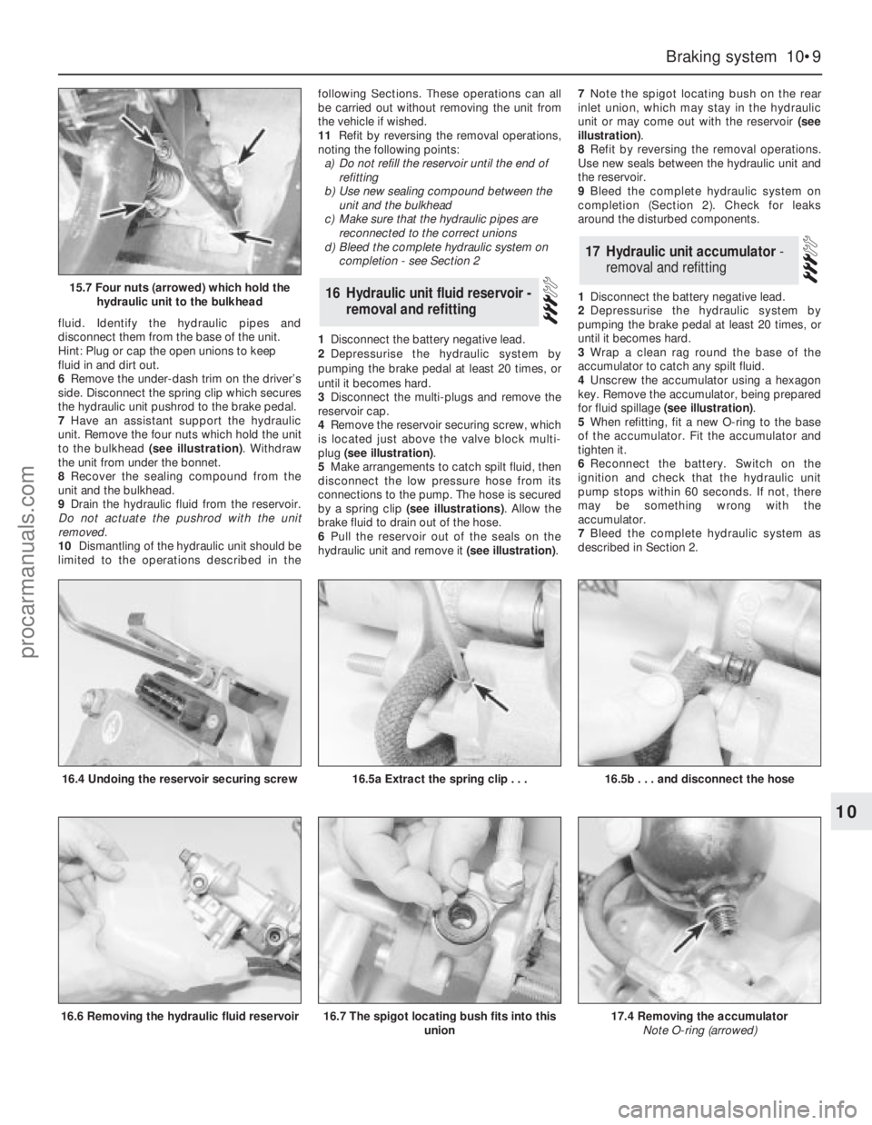
to the bulkhead (see illustration). Withdraw
the unit from under the bonnet.
8Recover the sealing compound from the
unit and the bulkhead.
9Drain the hydraulic fluid from the reservoir.
Do not actuate the pushrod with the unit
removed.
10Dismantling of the hydraulic unit should be
limited to the operations described in thefollowing Sections. These operations can all
be carried out without removing the unit from
the vehicle if wished.
11Refit by reversing the removal operations,
noting the following points:
a)Do not refill the reservoir until the end of
refitting
b)Use new sealing compound between the
unit and the bulkhead
c)Make sure that the hydraulic pipes are
reconnected to the correct unions
d)Bleed the complete hydraulic system on
completion - see Section 2
1Disconnect the battery negative lead.
2Depressurise the hydraulic system by
pumping the brake pedal at least 20 times, or
until it becomes hard.
3Disconnect the multi-plugs and remove the
reservoir cap.
4Remove the reservoir securing screw, which
is located just above the valve block multi-
plug (see illustration).
5Make arrangements to catch spilt fluid, then
disconnect the low pressure hose from its
connections to the pump. The hose is secured
by a spring clip (see illustrations). Allow the
brake fluid to drain out of the hose.
6Pull the reservoir out of the seals on the
hydraulic unit and remove it (see illustration).7Note the spigot locating bush on the rear
inlet union, which may stay in the hydraulic
unit or may come out with the reservoir (see
illustration).
8Refit by reversing the removal operations.
Use new seals between the hydraulic unit and
the reservoir.
9Bleed the complete hydraulic system on
completion (Section 2). Check for leaks
around the disturbed components.
1Disconnect the battery negative lead.
2Depressurise the hydraulic system by
pumping the brake pedal at least 20 times, or
until it becomes hard.
3Wrap a clean rag round the base of the
accumulator to catch any spilt fluid.
4Unscrew the accumulator using a hexagon
key. Remove the accumulator, being prepared
for fluid spillage (see illustration).
5When refitting, fit a new O-ring to the base
of the accumulator. Fit the accumulator and
tighten it.
6Reconnect the battery. Switch on the
ignition and check that the hydraulic unit
pump stops within 60 seconds. If not, there
may be something wrong with the
accumulator.
7Bleed the complete hydraulic system as
described in Section 2.
17Hydraulic unit accumulator -
removal and refitting
16Hydraulic unit fluid reservoir -
removal and refitting
Braking system 10•9
10
15.7 Four nuts (arrowed) which hold the
hydraulic unit to the bulkhead
16.4 Undoing the reservoir securing screw16.5a Extract the spring clip . . .
16.6 Removing the hydraulic fluid reservoir
16.5b . . . and disconnect the hose
16.7 The spigot locating bush fits into this
union17.4 Removing the accumulator
Note O-ring (arrowed)
procarmanuals.com
Page 141 of 255
3Press the multi-plug locking lever,
disconnect the multi-plug and unhook it from
the module. Remove the module.
4Refit by reversing the removal operations.
Make sure that the multi-plug is properly
engaged before refitting the module.
Front
1Ensure that the handbrake is applied. Raise
and support the front of the vehicle.
2From under the bonnet disconnect the
wheel sensor wiring multi-plug. Unclip the
wiring, working towards the sensor.
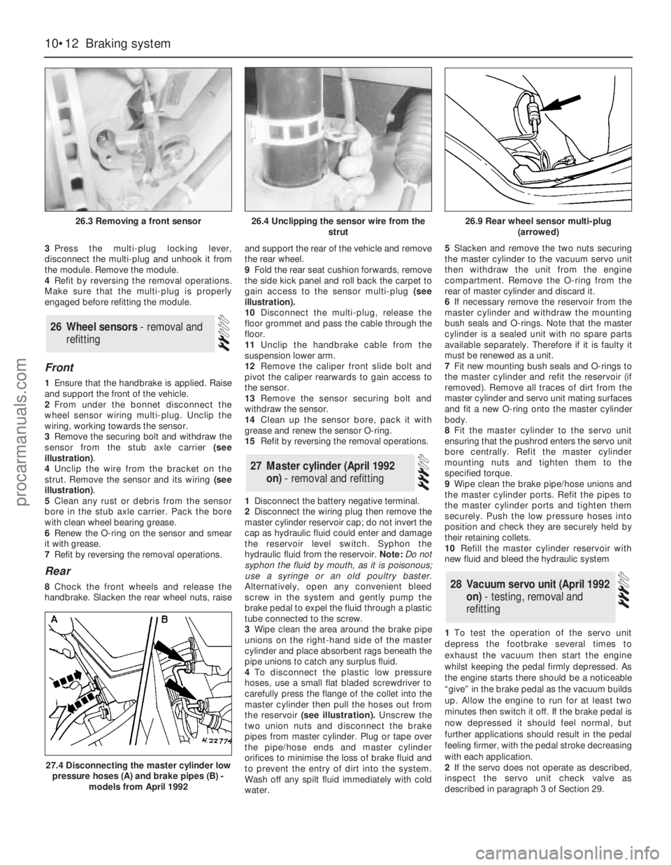
3Remove the securing bolt and withdraw the
sensor from the stub axle carrier (see
illustration).
4Unclip the wire from the bracket on the
strut. Remove the sensor and its wiring (see
illustration).
5Clean any rust or debris from the sensor
bore in the stub axle carrier. Pack the bore
with clean wheel bearing grease.
6Renew the O-ring on the sensor and smear
it with grease.
7Refit by reversing the removal operations.
Rear
8Chock the front wheels and release the
handbrake. Slacken the rear wheel nuts, raiseand support the rear of the vehicle and remove
the rear wheel.
9Fold the rear seat cushion forwards, remove
the side kick panel and roll back the carpet to
gain access to the sensor multi-plug (see
illustration).
10Disconnect the multi-plug, release the
floor grommet and pass the cable through the
floor.
11Unclip the handbrake cable from the
suspension lower arm.
12Remove the caliper front slide bolt and
pivot the caliper rearwards to gain access to
the sensor.
13Remove the sensor securing bolt and
withdraw the sensor.
14Clean up the sensor bore, pack it with
grease and renew the sensor O-ring.
15Refit by reversing the removal operations.
1Disconnect the battery negative terminal.
2Disconnect the wiring plug then remove the
master cylinder reservoir cap; do not invert the
cap as hydraulic fluid could enter and damage
the reservoir level switch. Syphon the
hydraulic fluid from the reservoir. Note: Do not
syphon the fluid by mouth, as it is poisonous;
use a syringe or an old poultry baster.
Alternatively, open any convenient bleed
screw in the system and gently pump the
brake pedal to expel the fluid through a plastic
tube connected to the screw.
3Wipe clean the area around the brake pipe
unions on the right-hand side of the master
cylinder and place absorbent rags beneath the
pipe unions to catch any surplus fluid.
4To disconnect the plastic low pressure
hoses, use a small flat bladed screwdriver to
carefully press the flange of the collet into the
master cylinder then pull the hoses out from
the reservoir(see illustration).Unscrew the
two union nuts and disconnect the brake
pipes from master cylinder. Plug or tape over
the pipe/hose ends and master cylinder
orifices to minimise the loss of brake fluid and
to prevent the entry of dirt into the system.
Wash off any spilt fluid immediately with cold
water.5Slacken and remove the two nuts securing
the master cylinder to the vacuum servo unit
then withdraw the unit from the engine
compartment. Remove the O-ring from the
rear of master cylinder and discard it.
6If necessary remove the reservoir from the
master cylinder and withdraw the mounting
bush seals and O-rings. Note that the master
cylinder is a sealed unit with no spare parts
available separately. Therefore if it is faulty it
must be renewed as a unit.
7Fit new mounting bush seals and O-rings to
the master cylinder and refit the reservoir (if
removed). Remove all traces of dirt from the
master cylinder and servo unit mating surfaces
and fit a new O-ring onto the master cylinder
body.
8Fit the master cylinder to the servo unit
ensuring that the pushrod enters the servo unit
bore centrally. Refit the master cylinder
mounting nuts and tighten them to the
specified torque.
9Wipe clean the brake pipe/hose unions and
the master cylinder ports. Refit the pipes to
the master cylinder ports and tighten them
securely. Push the low pressure hoses into
position and check they are securely held by
their retaining collets.
10Refill the master cylinder reservoir with
new fluid and bleed the hydraulic system
1To test the operation of the servo unit
depress the footbrake several times to
exhaust the vacuum then start the engine
whilst keeping the pedal firmly depressed. As
the engine starts there should be a noticeable
“give” in the brake pedal as the vacuum builds
up. Allow the engine to run for at least two
minutes then switch it off. If the brake pedal is
now depressed it should feel normal, but
further applications should result in the pedal
feeling firmer, with the pedal stroke decreasing
with each application.
2If the servo does not operate as described,
inspect the servo unit check valve as
describedin paragraph 3 of Section 29.28Vacuum servo unit (April 1992
on) - testing, removal and
refitting
27Master cylinder (April 1992
on) - removal and refitting
26Wheel sensors - removal and
refitting
10•12Braking system
26.3 Removing a front sensor
27.4 Disconnecting the master cylinder low
pressure hoses (A) and brake pipes (B) -
models from April 1992
26.4 Unclipping the sensor wire from the
strut26.9 Rear wheel sensor multi-plug
(arrowed)
procarmanuals.com
Page 161 of 255
Where serious damage has occurred or
large areas need renewal due to neglect, it
means certainly that completely new sections
or panels will need welding in and this is best
left to professionals. If the damage is due to
impact, it will also be necessary to completely
check the alignment of the bodyshell
structure. Due to the principle of construction,
the strength and shape of the whole car can
be affected by damage to one part. In such
instances the services of a Ford agent with
specialist checking jigs are essential. If a body
is left misaligned, it is first of all dangerous as
the car will not handle properly, and secondly
uneven stresses will be imposed on the
steering, engine and transmission, causing
abnormal wear or complete failure. Tyre wear
may also be excessive.
1Open and prop the bonnet.
2Mark around the bonnet hinge bolts, using
soft pencil or a washable marker pen, to
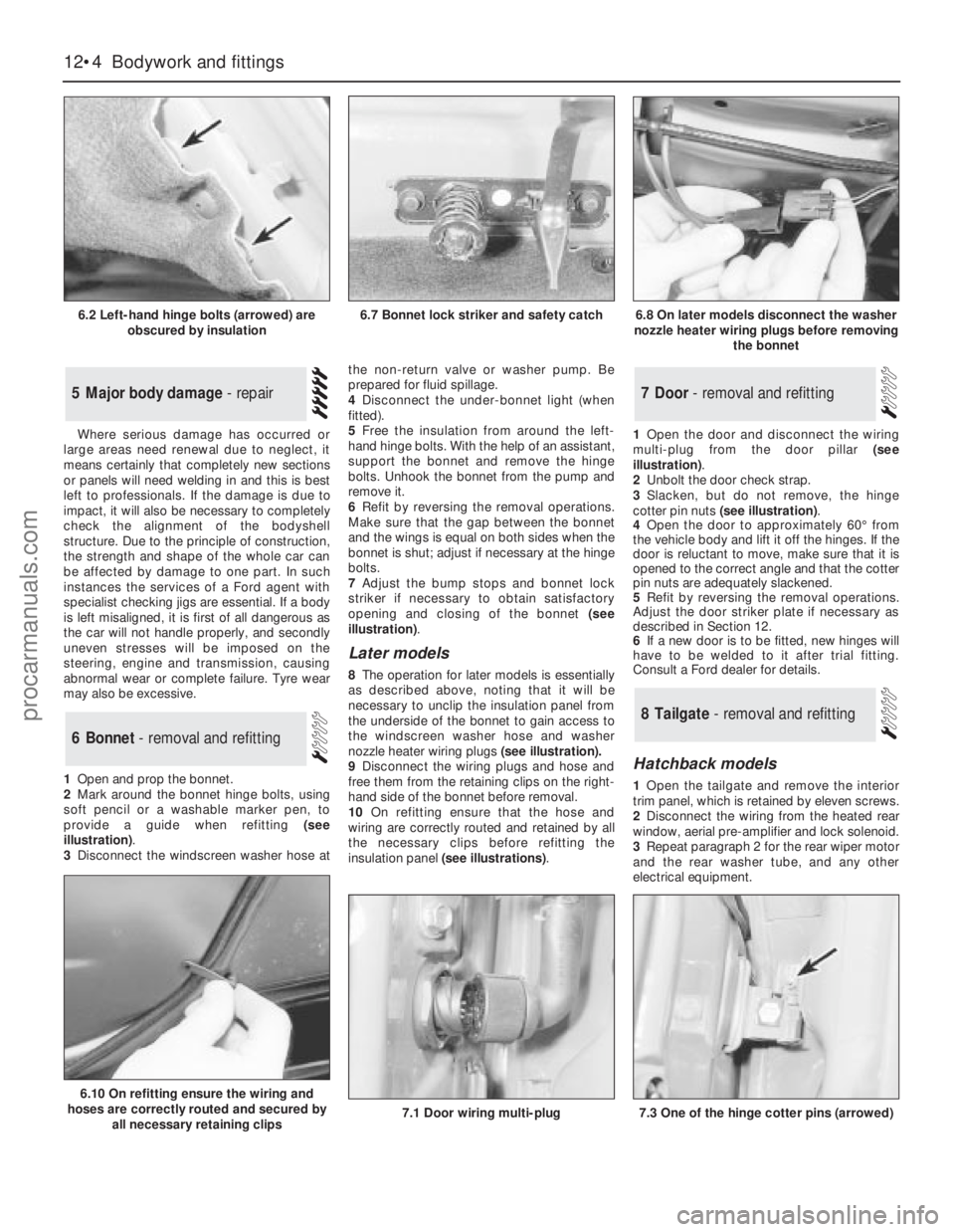
provide a guide when refitting (see
illustration).
3Disconnect the windscreen washer hose atthe non-return valve or washer pump. Be
prepared for fluid spillage.
4Disconnect the under-bonnet light (when
fitted).
5Free the insulation from around the left-
hand hinge bolts. With the help of an assistant,
support the bonnet and remove the hinge
bolts. Unhook the bonnet from the pump and
remove it.
6Refit by reversing the removal operations.
Make sure that the gap between the bonnet
and the wings is equal on both sides when the
bonnet is shut; adjust if necessary at the hinge
bolts.
7Adjust the bump stops and bonnet lock
striker if necessary to obtain satisfactory
opening and closing of the bonnet (see
illustration).
Later models
8The operation for later models is essentially
as described above, noting thatit will be
necessary to unclip the insulation panel from
the underside of the bonnet to gain access to
the windscreen washer hose and washer
nozzle heater wiring plugs (see illustration).
9Disconnect the wiring plugs and hose and
free them from the retaining clips on the right-
hand side of the bonnet before removal.
10On refitting ensure that the hose and
wiring are correctly routed and retained by all
the necessary clips before refitting the
insulation panel (see illustrations).1Open the door and disconnect the wiring
multi-plug from the door pillar (see
illustration).
2Unbolt the door check strap.
3Slacken, but do not remove, the hinge
cotter pin nuts (see illustration).
4Open the door to approximately 60°from
the vehicle body and lift it off the hinges. If the
door is reluctant to move, make sure that it is
opened to the correct angle and that the cotter
pin nuts are adequately slackened.
5Refit by reversing the removal operations.
Adjust the door striker plate if necessary as
described in Section 12.
6If a new door is to be fitted, new hinges will
have to be welded to it after trial fitting.
Consult a Ford dealer for details.
Hatchback models
1Open the tailgate and remove the interior
trim panel, which is retained by eleven screws.
2Disconnect the wiring from the heated rear
window, aerial pre-amplifier and lock solenoid.
3Repeat paragraph 2 for the rear wiper motor
and the rear washer tube, and any other
electrical equipment.
8Tailgate - removal and refitting
7Door - removal and refitting
6Bonnet - removal and refitting
5Major body damage - repair
12•4Bodywork and fittings
6.2 Left-hand hinge bolts (arrowed) are
obscured by insulation
6.10 On refitting ensure the wiring and
hoses are correctly routed and secured by
all necessary retaining clips
7.1 Door wiring multi-plug7.3 One of the hinge cotter pins (arrowed)
6.7 Bonnet lock striker and safety catch6.8 On later models disconnect the washer
nozzle heater wiring plugs before removing
the bonnet
procarmanuals.com