1985 FORD GRANADA gas mileage
[x] Cancel search: gas mileagePage 37 of 255

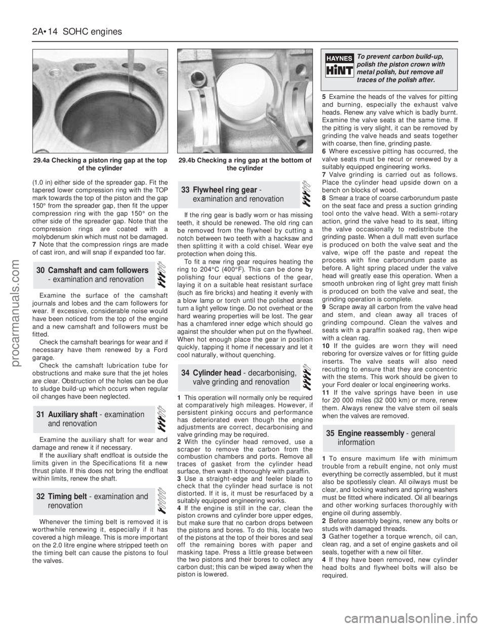
(1.0 in) either side of the spreader gap. Fit the
tapered lower compression ring with the TOP
mark towards the top of the piston and the gap
150°from the spreader gap, then fit the upper
compression ring with the gap 150°on the
other side of the spreader gap. Note that the
compression rings are coated with a
molybdenum skin which must not be damaged.
7Note that the compression rings are made
of cast iron, and will snap if expanded too far.
Examine the surface of the camshaft
journals and lobes and the cam followers for
wear. If excessive, considerable noise would
have been noticed from the top of the engine
and a new camshaft and followers must be
fitted.
Check the camshaft bearings for wear and if
necessary have them renewed by a Ford
garage.
Check the camshaft lubrication tube for
obstructions and make sure that the jet holes
are clear. Obstruction of the holes can be due
to sludge build-up which occurs when regular
oil changes have been neglected.
Examine the auxiliary shaft for wear and
damage and renew it if necessary.
If the auxiliary shaft endfloat is outside the
limits given in the Specifications fit a new
thrust plate. If this does not bring the endfloat
within limits, renew the shaft.
Whenever the timing belt is removed it is
worthwhile renewing it, especially if it has
covered a high mileage. This is more important
on the 2.0 litre engine where stripped teeth on
the timing belt can cause the pistons to foul
the valves.If the ring gear is badly worn or has missing
teeth, it should be renewed. The old ring can
be removed from the flywheel by cutting a
notch between two teeth with a hacksaw and
then splitting it with a cold chisel. Wear eye
protection when doing this.
To fit a new ring gear requires heating the
ring to 204°C (400°F). This can be done by
polishing four equal sections of the gear,
laying it on a suitable heat resistant surface
(such as fire bricks) and heating it evenly with
a blow lamp or torch until the polished areas
turn a light yellow tinge. Do not overheat or the
hard wearing properties will be lost. The gear
has a chamfered inner edge which should go
against the shoulder when put on the flywheel.
When hot enough place the gear in position
quickly, tapping it home if necessary and let it
cool naturally, without quenching.
1This operation will normally only be required
at comparatively high mileages. However, if
persistent pinking occurs and performance
has deteriorated even though the engine
adjustments are correct, decarbonising and
valve grinding may be required.
2With the cylinder head removed, use a
scraper to remove the carbon from the
combustion chambers and ports. Remove all
traces of gasket from the cylinder head
surface, then wash it thoroughly with paraffin.
3Use a straight-edge and feeler blade to
check that the cylinder head surface is not
distorted. If it is, it must be resurfaced by a
suitably equipped engineering works.
4If the engine is still in the car, clean the
piston crowns and cylinder bore upper edges,
but make sure that no carbon drops between
the pistons and bores. To do this, locate two
of the pistons at the top of their bores and seal
off the remaining bores with paper and
masking tape. Press a little grease between
the two pistons and their bores to collect any
carbon dust; this can be wiped away when the
piston is lowered.5Examine the heads of the valves for pitting
and burning, especially the exhaust valve
heads. Renew any valve which is badly burnt.
Examine the valve seats at the same time. If
the pitting is very slight, it can be removed by
grinding the valve heads and seats together
with coarse, then fine, grinding paste.
6Where excessive pitting has occurred, the
valve seats must be recut or renewed by a
suitably equipped engineering works.
7Valve grinding is carried out as follows.
Place the cylinder head upside down on a
bench on blocks of wood.
8Smear a trace of coarse carborundum paste
on the seat face and press a suction grinding
tool onto the valve head. With a semi-rotary
action, grind the valve head to its seat, lifting
the valve occasionally to redistribute the
grinding paste. When a dull matt even surface
is produced on both the valve seat and the
valve, wipe off the paste and repeat the
process with fine carborundum paste as
before. A light spring placed under the valve
head will greatly ease this operation. When a
smooth unbroken ring of light grey matt finish
is produced on both the valve and seat, the
grinding operation is complete.
9Scrape away all carbon from the valve head
and stem, and clean away all traces of
grinding compound. Clean the valves and
seats with a paraffin soaked rag, then wipe
with a clean rag.
10If the guides are worn they will need
reboring for oversize valves or for fitting guide
inserts. The valve seats will also need
recutting to ensure that they are concentric
with the stems. This work should be given to
your Ford dealer or local engineering works.
11If the valve springs have been in use
for 20 000 miles (32 000 km) or more, renew
them. Always renew the valve stem oil seals
when the valves are removed.
1To ensure maximum life with minimum
trouble from a rebuilt engine, not only must
everything be correctly assembled, but it must
also be spotlessly clean. All oilways must be
clear, and locking washers and spring washers
must be fitted where indicated. Oil all bearings
and other working surfaces thoroughly with
engine oil during assembly.
2Before assembly begins, renew any bolts or
studs with damaged threads.
3Gather together a torque wrench, oil can,
clean rag, and a set of engine gaskets and oil
seals, together with a new oil filter.
4If they have been removed, new cylinder
head bolts and flywheel bolts will also be
required.
35Engine reassembly - general
information
34Cylinder head - decarbonising,
valve grinding and renovation
33Flywheel ring gear -
examination and renovation
32Timing belt - examination and
renovation
31Auxiliary shaft - examination
and renovation
30Camshaft and cam followers
- examination and renovation
2A•14SOHCengines
29.4a Checking a piston ring gap at the top
of the cylinder29.4b Checking a ring gap at the bottom of
the cylinder
To prevent carbon build-up,
polish the piston crown with
metal polish, but remove all
traces of the polish after.
procarmanuals.com
Page 43 of 255

See Chapter 1, Section 23.
1Make a final check to ensure that everything
has been reconnected to the engine and that no
rags or tools have been left in the engine bay.
2Check that oil and coolant levels are
correct.
3Start the engine. This may take a little longer
than usual as fuel is pumped up to the engine.
4Check that the oil pressure light goes out
when the engine starts.
5Run the engine at a fast tickover and check
for leaks of oil, fuel and coolant. Also check
power steering and transmission fluid cooler
unions, when applicable. Some smoke and
odd smells may be experienced as assembly
lubricant burns off the exhaust manifold and
other components.6Bring the engine to operating temperature.
Check the ignition timing then adjust the idle
speed (if applicable) and mixture.
7Stop the engine and allow it to cool, then re-
check the oil and coolant levels.
8If new bearings, pistons etc have been
fitted, the engine should be run in at reduced
speeds and loads for the first 500 miles (800
km) or so. It is beneficial to change the engine
oil and filter after this mileage.
1When engine performance is down, or if
misfiring occurs which cannot be attributed to
the ignition or fuel system, a compression test
can provide diagnostic clues. If the test is
performed regularly it can give warning of
trouble before any other symptoms become
apparent.
2The engine must be at operating
temperature, the battery must be fully charged
and the spark plugs must be removed. The
services of an assistant will also be required.
3Disable the ignition system by dismantlingthe coil LT feed. Fit the compression tester to
No 1 spark plug hole. (The type of tester which
screws into the spark plug hole is to be
preferred.)
4Have the assistant hold the throttle wide
open and crank the engine on the starter.
Record the highest reading obtained on the
compression tester.
5Repeat the test on the remaining cylinders,
recording the pressure developed in each.
6Desired pressures are given in the
Specifications. If the pressure in any cylinder
is low, introduce a teaspoonful of clean engine
oil into the spark plug hole and repeat the test.
7If the addition of oil temporarily improves
the compression pressure, this indicates that
bore or piston wear was responsible for the
pressure loss. No improvement suggests that
leaking or burnt valves, or a blown head
gasket, may be to blame.
8A low reading from two adjacent cylinders is
almost certainly due to the head gasket
between them having blown.
9On completion of the test, refit the spark
plugs and reconnect the coil LT feed.
52Compression test -
description and interpretation
51Initial start-up after overhaul
or major repair
50Valve clearances - checking
and adjustment
2A•20SOHCengines
procarmanuals.com
Page 58 of 255

d)Disconnect the breather hose from the
camshaft cover.
e)Remove the distributor cap and HT leads,
and the rotor arm and housing. If
necessary, mark the HT leads to aid
refitting.
2Proceed as described in paragraphs 2 to 15
inclusive of Section 18.
3Examine the surfaces of the camshaft
journals and lobes and the contact surfaces of
the cam followers for wear. If wear is
excessive, considerable noise would have
been noticed from the top of the engine when
running, and new camshafts and followers
must be fitted. It is unlikely that this level of
wear will occur unless a considerable mileage
has been covered. Note that the cam followers
cannot be dismantled for renewal of individual
components.
4Check the camshaft bearing surfaces in the
cylinder head and the bearing caps for wear. If
excessive wear is evident, the only course of
action available is to renew the cylinder head
complete with bearing caps.
5Check the cam follower bores in the
cylinder head for wear. If excessive wear is
evident, the cylinder head must be renewed.
6Check the cam follower oil grooves and the
oil ports in the cylinder head for obstructions.
7Refit the cam followers and the camshafts as
described in paragraphs 27 to 55 of Section 18.
8If the engine is in the vehicle, reverse the
operations given in paragraph 1.
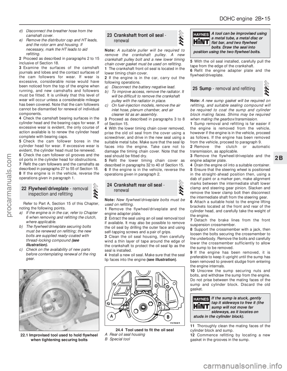
Refer to Part A, Section 15 of this Chapter,
noting the following points.
a)If the engine is in the car, refer to Chapter
6 when removing and refitting the clutch,
where applicable.
b)The flywheel/driveplate securing bolts
must be renewed on refitting; the new
bolts are supplied ready-coated with
thread-locking compound (see
illustration).
c)Check on the availability of new parts
before contemplating renewal of the ring
gear.Note: A suitable puller will be required to
remove the crankshaft pulley. A new
crankshaft pulley bolt and a new lower timing
chain cover gasket must be used on refitting.
1The crankshaft front oil seal is located in the
lower timing chain cover.
2If the engine is in the car, carry out the
following operations.
a)Disconnect the battery negative lead.
b)To improve access, remove the radiator. It
will be difficult to remove the crankshaft
pulley with the radiator in place.
c)On fuel-injection models, remove the air
inlet hose, plenum chamber, and air
cleaner lid as an assembly.
3Proceed as described in paragraphs 3 to 8
of Section 15.
4With the lower timing chain cover removed,
prise the old oil seal from the cover using a
screwdriver, and drive in the new seal using a
suitable metal tube. Make sure that the seal lip
faces into the engine. Take care not to
damage the timing chain cover. Note that the
seal should be fitted dry.
5Refit the lower timing chain cover as
described in paragraphs 32 to 40 of Section 15.
6If the engine is in the vehicle, reverse the
operations given in paragraph 2.
Note: New flywheel/driveplate bolts must be
used on refitting.
1Remove the flywheel/driveplate and the
engine adapter plate.
2Extract the seal using an oil seal removal tool
if available. It may also be possible to remove
the oil seal by drilling the outer face and using
self-tapping screws and a pair of grips.
3Clean the oil seal housing, then carefully
wind a thin layer of tape around the edge of
the crankshaft to protect the oil seal lip as the
seal is installed.
4Install a new oil seal. Make sure that the seal
lip faces into the engine (see illustration).5With the oil seal installed, carefully pull the
tape from the edge of the crankshaft.
6Refit the engine adapter plate and the
flywheel/driveplate.
Note: A new sump gasket will be required on
refitting, and suitable sealing compound will
be required to coat the sump and cylinder
block mating faces. Shims may be required
when mating the gearbox/transmission.
1Sump removal and refitting is far easier if
the engine is removed from the vehicle,
however if the engine is in the vehicle, proceed
as follows. If the engine has been removed
from the vehicle, proceed to paragraph 9.
2Remove the clutch or automatic
transmission, as applicable.
3Remove the flywheel/driveplate and the
engine adapter plate.
4Drain the engine oil into a suitable container.
5Ensure that the steering wheel is positioned
in the straight-ahead position then, using a
dab of paint or a marker pen, make alignment
marks between the intermediate shaft lower
clamp and steering gear pinion. Slacken and
remove the lower clamp bolt then disconnect
the intermediate shaft from the steering gear.
6Attach a suitable hoist to the engine lifting
brackets located at the front and rear of the
cylinder head, and carefully take the weight of
the engine.
7Detach the brake lines from the front
suspension crossmember.
8Support the crossmember with a jack, then
loosen the bolts securing the crossmember to
the underbody. Remove the bolts and carefully
lower the crossmember sufficiently to allow
the sump to be removed.
9If the engine has been removed, it is
preferable to keep it upright until the sump has
been removed to prevent sludge from entering
the engine internals.
10Unscrew the sump securing nuts and
bolts, and withdraw the sump from the engine.
Do not prise between the mating faces of the
sump and cylinder block. Discard the old
gasket.
11Thoroughly clean the mating faces of the
cylinder block and sump.
12Commence refitting by locating a new
gasket in the grooves in the sump.
25Sump - removal and refitting
24Crankshaft rear oil seal -
renewal
23Crankshaft front oil seal -
renewal
22Flywheel/driveplate - removal
inspection and refitting
DOHCengine 2B•15
2B
22.1 Improvised tool used to hold flywheel
when tightening securing bolts
24.4 Tool used to fit the oil seal
A Rear oil seal housing
B Special tool
A tool can be improvised using
a metal tube, a metal disc or
flat bar, and two flywheel
bolts.Draw the seal into
position using the two flywheel bolts.
If the sump is stuck, gently
tap it sideways to free it (the
sump will not move far
sideways, as it locates on
studs in the cylinder block).
procarmanuals.com
Page 242 of 255

Engine misfires throughout the driving speed range
m mFuel filter choked (Chapter 1).
m mFuel pump faulty, or delivery pressure low (Chapter 4).
m mFuel tank vent blocked, or fuel pipes restricted (Chapter 4).
m mVacuum leak at the throttle body, inlet manifold or associated hoses
(Chapter 4).
m mWorn, faulty or incorrectly-gapped spark plugs (Chapter 1).
m mFaulty spark plug HT leads (Chapter 5).
m mDistributor cap cracked or tracking internally (Chapter 5).
m mFaulty ignition coil (Chapter 5).
m mUneven or low cylinder compressions (Chapter 2).
m mFuel injection system fault (Chapter 4).
Engine hesitates on acceleration
m
mWorn, faulty or incorrectly-gapped spark plugs (Chapter 1).
m mVacuum leak at the throttle body, inlet manifold or associated hoses
(Chapter 4).
m mFuel injection system fault (Chapter 4).
Engine stalls
m
mVacuum leak at the throttle body, inlet manifold or associated hoses
(Chapter 4).
m mFuel filter choked (Chapter 1).
m mFuel pump faulty, or delivery pressure low (Chapter 4).
m mFuel tank vent blocked, or fuel pipes restricted (Chapter 4).
m mFuel injection system fault (Chapter 4).
Engine lacks power
m
mFuel filter choked (Chapter 1).
m mFuel pump faulty, or delivery pressure low (Chapter 4).
m mUneven or low cylinder compressions (Chapter 2).
m mWorn, faulty or incorrectly-gapped spark plugs (Chapter 1).
m mVacuum leak at the throttle body, inlet manifold or associated hoses
(Chapter 4).
m mFuel injection system fault (Chapter 4).
m mBrakes binding (Chapters 1 and 10).
m mClutch slipping (Chapter 6).
Engine backfires
m
mVacuum leak at the throttle body, inlet manifold or associated hoses
(Chapter 4).
m mFuel injection system fault (Chapter 4).
Oil pressure warning light illuminated with engine
running
m mLow oil level, or incorrect oil grade (Chapter 1).
m mFaulty oil pressure sensor (Chapter 2).
m mWorn engine bearings and/or oil pump (Chapter 2).
m mExcessively high engine operating temperature (Chapter 3).
m mOil pressure relief valve defective (Chapter 2).
m mOil pick-up strainer clogged (Chapter 2).
Note:Low oil pressure in a high-mileage engine at tickover is not
necessarily a cause for concern. Sudden pressure loss at speed is far
more significant. In any event, check the gauge or warning light sender
before condemning the engine.
Engine runs-on after switching off
m mExcessive carbon build-up in engine (Chapter 2).
m mExcessively high engine operating temperature (Chapter 3).
Engine noises
Pre-ignition (pinking) or knocking during acceleration or
under load
m mIgnition timing incorrect/ignition system fault (Chapters 1 and 5).
m mIncorrect grade of spark plug (Chapter 1).
m mIncorrect grade of fuel (Chapter 1).
m mVacuum leak at throttle body, inlet manifold or associated hoses
(Chapter 4).
m mExcessive carbon build-up in engine (Chapter 2).
m mFuel injection system fault (Chapter 4).
Whistling or wheezing noises
m
mLeaking inlet manifold or throttle body gasket (Chapter 4).
m mLeaking exhaust manifold gasket (Chapter 4).
m mLeaking vacuum hose (Chapters 4 and 10).
m mBlowing cylinder head gasket (Chapter 2).
Tapping or rattling noises
m
mWorn valve gear, timing chain, camshaft or hydraulic tappets
(Chapter 2).
m mAncillary component fault (water pump, alternator, etc) (Chapters 3,
5, etc).
Knocking or thumping noises
m mWorn big-end bearings (regular heavy knocking, perhaps less under
load) (Chapter 2).
m mWorn main bearings (rumbling and knocking, perhaps worsening
under load) (Chapter 2).
m mPiston slap (most noticeable when cold) (Chapter 2).
m mAncillary component fault (water pump, alternator, etc) (Chapters 3,
5, etc).
REF•7Fault Finding
2Cooling system
Overheating
m
mAuxiliary drivebelt broken or incorrectly adjusted (Chapter 1).
m mInsufficient coolant in system (Chapter 1).
m mThermostat faulty (Chapter 3).
m mRadiator core blocked, or grille restricted (Chapter 3).
m mElectric cooling fan or thermostatic switch faulty (Chapter 3).
m mViscous-coupled fan faulty (Chapter 3).
m mIgnition timing incorrect, or ignition system fault (Chapters 1 and 5).
m mInaccurate temperature gauge sender unit (Chapter 3).
m mAirlock in cooling system (Chapter 3).
Overcooling
m
mThermostat faulty (Chapter 3).
m mInaccurate temperature gauge sender unit (Chapter 3).
External coolant leakage
m
mDeteriorated or damaged hoses or hose clips (Chapter 1).
m mRadiator core or heater matrix leaking (Chapter 3).
m mPressure cap faulty (Chapter 3).
m mWater pump internal seal leaking (Chapter 3).
m mWater pump-to-block seal leaking (Chapter 3).
m mBoiling due to overheating (Chapter 3).
m mCore plug leaking (Chapter 2).
Internal coolant leakage
m
mLeaking cylinder head gasket (Chapter 2).
m mCracked cylinder head or cylinder block (Chapter 2).
Corrosion
m
mInfrequent draining and flushing (Chapter 1).
m mIncorrect coolant mixture or inappropriate coolant type (Chapter 1).
procarmanuals.com