1985 FORD GRANADA jacking
[x] Cancel search: jackingPage 5 of 255
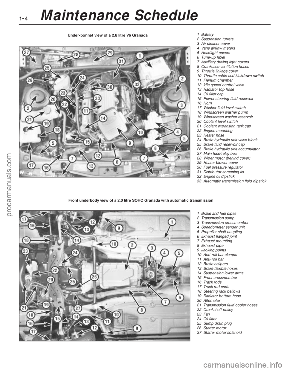
1•4Maintenance Schedule
1 Battery
2 Suspension turrets
3 Air cleaner cover
4 Vane airflow meters
5 Headlight covers
6 Tune-up label
7 Auxiliary driving light covers
8 Crankcase ventilation hoses
9 Throttle linkage cover
10 Throttle cable and kickdown switch
11 Plenum chamber
12 Idle speed control valve
13 Radiator top hose
14 Oil filler cap
15 Power steering fluid reservoir
16 Horn
17 Washer fluid level switch
18 Windscreen washer pump
19 Windscreen washer reservoir
20 Coolant level switch
21 Coolant expansion tank cap
22 Engine mounting
23 Heater hose
24 Brake hydraulic unit valve block
25 Brake fluid reservoir cap
26 Brake hydraulic unit accumulator
27 Main fuse/relay box
28 Wiper motor (behind cover)
29 Heater blower cover
30 Fuel pressure regulator
31 Distributor screening lid
32 Engine oil dipstick
33 Automatic transmission fluid dipstick Under-bonnet view of a 2.8 litre V6 Granada
1 Brake and fuel pipes
2 Transmission sump
3 Transmission crossmember
4 Speedometer sender unit
5 Propeller shaft coupling
6 Exhaust flanged joint
7 Exhaust mounting
8 Exhaust pipe
9 Jacking points
10 Anti-roll bar clamps
11 Anti-roll bar
12 Brake calipers
13 Brake flexible hoses
14 Suspension lower arms
15 Front crossmember
16 Track rods
17 Track rod ends
18 Steering rack bellows
19 Radiator bottom hose
20 Alternator
21 Transmission fluid cooler hoses
22 Crankshaft pulley
23 Fan
24 Oil filter
25 Sump drain plug
26 Starter motor
27 Starter motor solenoid Front underbody view of a 2.0 litre SOHC Granada with automatic transmission
procarmanuals.com
Page 6 of 255
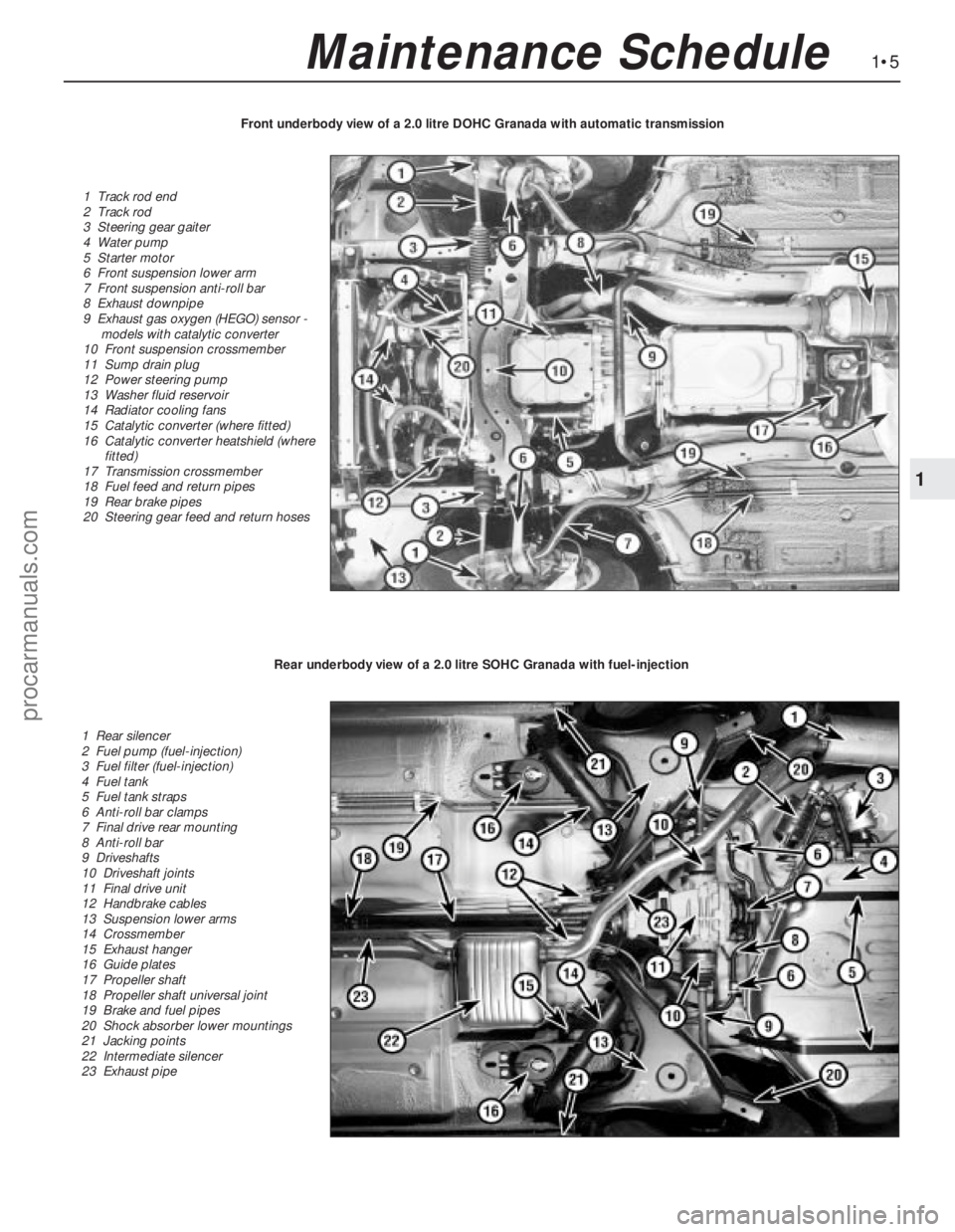
1•5
1
Maintenance Schedule
1 Track rod end
2 Track rod
3 Steering gear gaiter
4 Water pump
5 Starter motor
6 Front suspension lower arm
7 Front suspension anti-roll bar
8 Exhaust downpipe
9 Exhaust gas oxygen (HEGO) sensor -
models with catalytic converter
10 Front suspension crossmember
11 Sump drain plug
12 Power steering pump
13 Washer fluid reservoir
14 Radiator cooling fans
15 Catalytic converter (where fitted)
16 Catalytic converter heatshield (where
fitted)
17 Transmission crossmember
18 Fuel feed and return pipes
19 Rear brake pipes
20 Steering gear feed and return hosesFront underbody view of a 2.0 litre DOHC Granada with automatic transmission
1 Rear silencer
2 Fuel pump (fuel-injection)
3 Fuel filter (fuel-injection)
4 Fuel tank
5 Fuel tank straps
6 Anti-roll bar clamps
7 Final drive rear mounting
8 Anti-roll bar
9 Driveshafts
10 Driveshaft joints
11 Final drive unit
12 Handbrake cables
13 Suspension lower arms
14 Crossmember
15 Exhaust hanger
16 Guide plates
17 Propeller shaft
18 Propeller shaft universal joint
19 Brake and fuel pipes
20 Shock absorber lower mountings
21 Jacking points
22 Intermediate silencer
23 Exhaust pipe
Rear underbody view of a 2.0 litre SOHC Granada with fuel-injection
procarmanuals.com
Page 10 of 255
3Persistent need for topping-up the battery
electrolyte suggests either that the alternator
output is excessive. or that the battery is
approaching the end of its life.
4Further information on the battery, charging
and jump-starting can be found in Chapter 5,
and in the preliminary Sections of this manual.1Clean the wiper blades and the windscreen,
using a solution of concentrated washer fluid
or methylated spirit. Similarly clean the
headlight lens and wiper blades.
2Check the condition of the wiper blades; if
they are cracked or show any signs of
deterioration, or if the glass swept area is
smeared, renew them. At the same time,
check the headlight wiper blades (where fitted)
for condition, and renew if necessary.
3To remove a blade, hinge the arm and blade
away from the screen. Press the tab on the
spring clip in the middle of the blade and
unhook the blade from the arm. 4Refit the blade by sliding it onto the hook on
the arm(see illustration).
5Check that the windscreen washer jets
operate correctly, and direct the washer fluid
towards the upper area of the wiper blade
stroke. If necessary, use a pin to reposition the
washer jets.
7Wiper blade check
1Before starting this procedure, gather
together all the necessary tools and materials.
Also make sure that you have plenty of clean
rags and newspapers handy, to mop up any
spills. Ideally, the engine oil should be warm,
as it will drain better, and more built-up sludge
will be removed with it. Take care, however,
not to touch the exhaust or any other hot parts
of the engine when working under the vehicle.
To avoid any possibility of scalding, and toprotect yourself from possible skin irritants
and other harmful contaminants in used
engine oils, it is advisable to wear gloves when
carrying out this work.
2Access to the underside of the vehicle will be
greatly improved if it can be raised on a lift,
driven onto ramps, or jacked up and supported
on axle stands (see “Jacking”). Whichever
method is chosen, make sure that the vehicle
remains level, or if it is at an angle, that the drain
plug is at the lowest point.
3Slacken the drain plug about half a turn.
Position the draining container under the drain
plug, then remove the plug completely. If
possible, try to keep the plug pressed into the
sump while unscrewing it by hand the last
couple of turns. As the plug releases from the
threads, move it away sharply so the stream of
oil issuing from the sump runs into the
container, not up your sleeve. Recover the
sealing washer from the drain plug.
4Allow some time for the old oil to drain,
noting that it may be necessary to reposition
the container as the oil flow slows to a trickle.
5After all the oil has drained, wipe off the
drain plug with a clean rag. Check the sealing
washer for condition, and renew it if
necessary. Clean the area around the drain
plug opening, and refit the plug. Tighten the
plug to the specified torque.
6Move the container into position under the
oil filter. On SOHC engines, the filter is located
on the left-hand side of the cylinder block in
front of the engine bearer. On DOHC and V6
engines, the filter is located on the right-hand
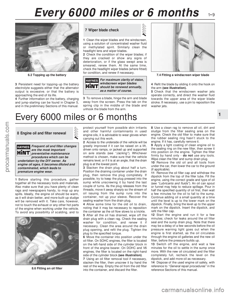
side of the cylinder block (see illustration).
7Using an oil filter removal tool if necessary,
slacken the filter, then unscrew it by hand the
rest of the way. Empty the oil from the old filter
into the container, and discard the filter.8Use a clean rag to remove all oil, dirt and
sludge from the filter sealing area on the
engine. Check the old filter to make sure that
the rubber sealing ring hasn’t stuck to the
engine. If it has, carefully remove it.
9Apply a light coating of clean engine oil to
the sealing ring on the new filter, then screw it
into position on the engine. Tighten the filter
firmly by hand only - do notuse any tools.
Wipe clean the filter and sump drain plug.
10Remove the old oil and all tools from
under the car, then lower the car to the ground
(if applicable).
11Remove the oil filler cap and withdraw the
dipstick from the top of the filler tube. Fill the
engine, using the correct grade and type of oil
(see “Lubricants and fluids”). An oil can spout
or funnel may help to reduce spillage. Pour in
half the specified quantity of oil first, then wait
a few minutes for the oil to fall to the sump.
Continue adding oil a small quantity at a time
until the level is up to the lower mark on the
dipstick. Finally, bring the level up to the upper
mark on the dipstick. Insert the dipstick, and
refit the filler cap.
12Start the engine and run it for a few
minutes; check for leaks around the oil filter
seal and the sump drain plug. Note that there
may be a delay of a few seconds before the oil
pressure warning light goes out when the
engine is first started, as the oil circulates
through the engine oil galleries and the new oil
filter, before the pressure builds up.
13Switch off the engine, and wait a few
minutes for the oil to settle in the sump once
more. With the new oil circulated and the filter
completely full, recheck the level on the
dipstick, and add more oil as necessary.
14Dispose of the used engine oil safely, with
reference to “General repair procedures”in the
reference Sections of this manual.
8Engine oil and filter renewal
1•9
1
Every 6000 miles or 6 months
8.6 Fitting an oil filter
6.2 Topping up the battery7.4 Fitting a windscreen wiper blade
Every 6000 miles or 6 months
For maximum clarity of vision,
windscreen wiper blades
should be renewed annually,
as a matter of course.
Frequent oil and filter changes
are the most important
preventative maintenance
procedures which can be
undertaken by the DIY owner. As
engine oil ages, it becomes diluted and
contaminated, which leads to
premature engine wear.
procarmanuals.com
Page 11 of 255
1Firmly apply the handbrake, then jack up the
front and rear of the car and support it
securely on axle stands (see “Jacking”).
2For a quick check, the front brake disc pads
can be inspected without removing the front
wheels, using a mirror and a torch through the
aperture in the rear face of the caliper. If any
one pad is worn down to the minimum
specified, all four pads (on both front wheels)
must be renewed.
3It is necessary to remove the rear wheels in
order to inspect the rear pads. The pads can
be viewed through the top of the caliper after
removing the spring clip. If any one pad is
worn down to the minimum specified, all four
pads (on both rear wheels) must be renewed.
4For a comprehensive check, the brake pads
should be removed and cleaned. The
operation of the caliper can then also be
checked, and the condition of the brake discs
can be fully examined on both sides. Refer to
Chapter 10 for further information.
5At the same interval, check the function of
the brake fluid level warning light. Chock the
wheels, release the handbrake and switch on
the ignition. Unscrew and raise the brake fluid
reservoir cap whilst an assistant observes the
warning light: it should come on as the level
sensor is withdrawn from the fluid. Refit the
cap.
6On completion, refit the wheels and lower
the car to the ground.
1Visually inspect the engine joint faces,
gaskets and seals for any signs of water or oil
leaks. Pay particular attention to the areas
around the rocker cover, cylinder head, oil
filter and sump joint faces. Bear in mind that
over a period of time some very slight seepage
from these areas is to be expected but what
you are really looking for is any indication of a
serious leak. Should a leak be found, renew
the offending gasket or oil seal by referring to
the appropriate Chapter(s) in this manual.
2Similarly, check the transmission for oil
leaks, and investigate and rectify and
problems found.
3Check the security and condition of all the
engine related pipes and hoses. Ensure that all
cable-ties or securing clips are in place and in
good condition. Clips which are broken or
missing can lead to chafing of the hoses,
pipes or wiring which could cause more
serious problems in the future.
4Carefully check the condition of all coolant,
fuel and brake hoses. Renew any hose which
is cracked, swollen or deteriorated. Cracks will
show up better if the hose is squeezed. Pay
close attention to the hose clips that secure
the hoses to the system components. Hoseclips can pinch and puncture hoses, resulting
in leaks. If wire type hose clips are used, it
may be a good idea to replace them with
screw-type clips.
5With the vehicle raised, inspect the fuel tank
and filler neck for punctures, cracks and other
damage. The connection between the filler neck
and tank is especially critical. Sometimes a
rubber filler neck or connecting hose will leak due
to loose retaining clamps or deteriorated rubber.
6Similarly, inspect all brake hoses and metal
pipes. If any damage or deterioration is
discovered, do not drive the vehicle until the
necessary repair work has been carried out.
Renew any damaged sections of hose or pipe.
7Carefully check all rubber hoses and metal
fuel lines leading away from the petrol tank.
Check for loose connections, deteriorated
hoses, crimped lines and other damage. Pay
particular attention to the vent pipes and
hoses which often loop up around the filler
neck and can become blocked or crimped.
Follow the lines to the front of the vehicle
carefully inspecting them all the way. Renew
damaged sections as necessary.
8From within the engine compartment, check
the security of all fuel hose attachments and
pipe unions, and inspect the fuel hoses and
vacuum hoses for kinks, chafing and
deterioration.
9Where applicable, check the condition of
the oil cooler hoses and pipes.
10Check the condition of all exposed wiring
harnesses.
11Also check the engine and transmission
components for signs of fluid leaks.
Periodically check the belts for fraying or
other damage. If evident, renew the belt.
If the belts become dirty, wipe them with a
damp cloth using a little detergent only.
Check the tightness of the anchor bolts and
if they are ever disconnected, make quite sure
that the original sequence of fitting of washers,
bushes and anchor plates is retained.With the vehicle raised on a hoist or
supported on axle stands (see “Jacking”),
check the exhaust system for signs of leaks,
corrosion or damage and check the rubber
mountings for condition and security. Where
damage or corrosion are evident, renew the
system complete or in sections, as applicable,
using the information given in Chapter 4.
With the wheels on the ground, slacken
each wheel nut by a quarter turn, then
retighten it immediately to the specified
torque.
Remove and clean the oil filler cap of any
sludge build-up using paraffin.
Inspect the vent hose for blockage or
damage. A blocked hose can cause a build-up
of crankcase pressure, which in turn can
cause oil leaks.
An accurate tachometer (rev. counter) will
be needed to adjust the idle speed. The
engine must be at operating temperature, the
air cleaner element must be clean and the
vacuum hoses fitted, and the engine valve
clearances must be correct. The ignition
system must also be in good condition.
Connect the tachometer to the engine as
instructed by the manufacturers. Start the
engine and allow it to idle. Read the speed
from the tachometer and compare it with the
value in the Specifications of Chapter 4
(Pierburg 2V carburettor).
If adjustment is necessary, turn the idle
speed adjustment screw. Turn the screw
clockwise to increase the speed, and anti-
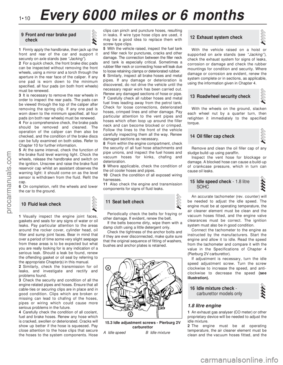
clockwise to decrease the speed (see
illustration).
1.8 litre engine
1An exhaust gas analyser (CO meter) or other
proprietary device will be needed to adjust the
idle mixture.
2The engine must be at operating
temperature, the air cleaner element must be
clean and the vacuum hoses fitted, and the
16Idle mixture check -
carburettor models only
15Idle speed check - 1.8 litre
SOHC
14Oil filler cap check
13Roadwheel security check
12Exhaust system check
11Seat belt check10Fluid leak check
9Front and rear brake pad
check
1•10Every 6000 miles or 6 months
15.3 Idle adjustment screws - Pierburg 2V
carburettor
A Idle speedB Idle mixture
procarmanuals.com
Page 16 of 255
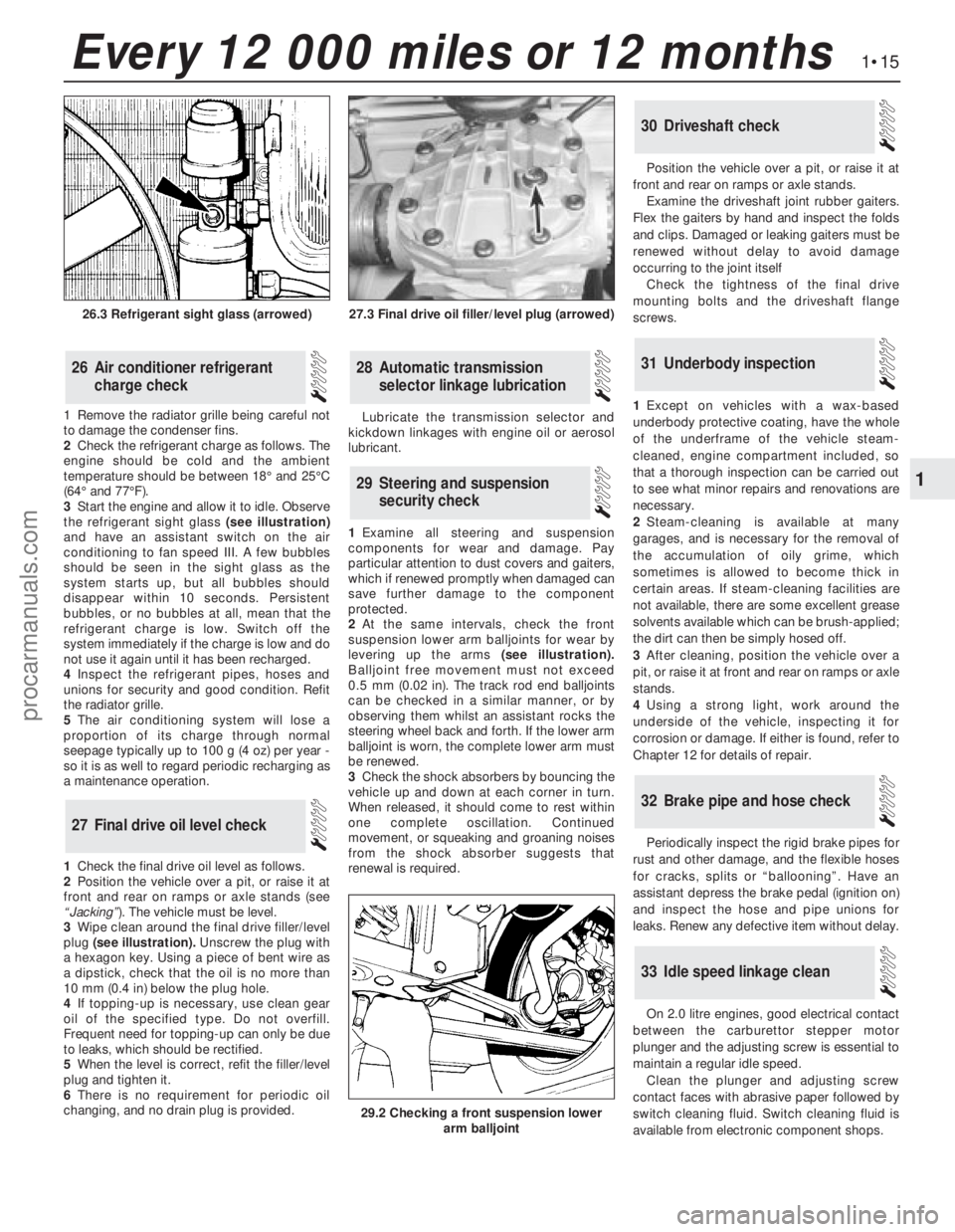
1Remove the radiator grille being careful not
to damage the condenser fins.
2Check the refrigerant charge as follows. The
engine should be cold and the ambient
temperature should be between 18°and 25°C
(64°and 77°F).
3Start the engine and allow it to idle. Observe
the refrigerant sight glass(see illustration)
and have an assistant switch on the air
conditioning to fan speed III. A few bubbles
should be seen in the sight glass as the
system starts up, but all bubbles should
disappear within 10 seconds. Persistent
bubbles, or no bubbles at all, mean that the
refrigerant charge is low. Switch off the
system immediately if the charge is low and do
not use it again until it has been recharged.
4Inspect the refrigerant pipes, hoses and
unions for security and good condition. Refit
the radiator grille.
5The air conditioning system will lose a
proportion of its charge through normal
seepage typically up to 100 g (4 oz) per year -
so it is as well to regard periodic recharging as
a maintenance operation.
1Check the final drive oil level as follows.
2Position the vehicle over a pit, or raise it at
front and rear on ramps or axle stands (see
“Jacking”). The vehicle must be level.
3Wipe clean around the final drive filler/level
plug (see illustration).Unscrew the plug with
a hexagon key. Using a piece of bent wire as
a dipstick, check that the oil is no more than
10 mm (0.4 in) below the plug hole.
4If topping-up is necessary, use clean gear
oil of the specified type. Do not overfill.
Frequent need for topping-up can only be due
to leaks, which should be rectified.
5When the level is correct, refit the filler/level
plug and tighten it.
6There is no requirement for periodic oil
changing, and no drain plug is provided. Lubricate the transmission selector and
kickdown linkages with engine oil or aerosol
lubricant.
1Examine all steering and suspension
components for wear and damage. Pay
particular attention to dust covers and gaiters,
which if renewed promptly when damaged can
save further damage to the component
protected.
2At the same intervals, check the front
suspension lower arm balljoints for wear by
levering up the arms(see illustration).
Balljoint free movement must not exceed
0.5 mm (0.02 in). The track rod end balljoints
can be checked in a similar manner, or by
observing them whilst an assistant rocks the
steering wheel back and forth. If the lower arm
balljoint is worn, the complete lower arm must
be renewed.
3Check the shock absorbers by bouncing the
vehicle up and down at each corner in turn.
When released, it should come to rest within
one complete oscillation. Continued
movement, or squeaking and groaning noises
from the shock absorber suggests that
renewal is required.Position the vehicle over a pit, or raise it at
front and rear on ramps or axle stands.
Examine the driveshaft joint rubber gaiters.
Flex the gaiters by hand and inspect the folds
and clips. Damaged or leaking gaiters must be
renewed without delay to avoid damage
occurring to the joint itself
Check the tightness of the final drive
mounting bolts and the driveshaft flange
screws.
1Except on vehicles with a wax-based
underbody protective coating, have the whole
of the underframe of the vehicle steam-
cleaned, engine compartment included, so
that a thorough inspection can be carried out
to see what minor repairs and renovations are
necessary.
2Steam-cleaning is available at many
garages, and is necessary for the removal of
the accumulation of oily grime, which
sometimes is allowed to become thick in
certain areas. If steam-cleaning facilities are
not available, there are some excellent grease
solvents available which can be brush-applied;
the dirt can then be simply hosed off.
3After cleaning, position the vehicle over a
pit, or raise it at front and rear on ramps or axle
stands.
4Using a strong light, work around the
underside of the vehicle, inspecting it for
corrosion or damage. If either is found, refer to
Chapter 12 for details of repair.
Periodically inspect the rigid brake pipes for
rust and other damage, and the flexible hoses
for cracks, splits or “ballooning”. Have an
assistant depress the brake pedal (ignition on)
and inspect the hose and pipe unions for
leaks. Renew any defective item without delay.
On 2.0 litre engines, good electrical contact
between the carburettor stepper motor
plunger and the adjusting screw is essential to
maintain a regular idle speed.
Clean the plunger and adjusting screw
contact faces with abrasive paper followed by
switch cleaning fluid. Switch cleaning fluid is
available from electronic component shops.
33Idle speed linkage clean
32Brake pipe and hose check
31Underbody inspection
30Driveshaft check
29Steering and suspension
security check
28Automatic transmission
selector linkage lubrication
27Final drive oil level check
26Air conditioner refrigerant
charge check
1•15
1
Every 12 000 miles or 12 months
27.3 Final drive oil filler/level plug (arrowed)
29.2 Checking a front suspension lower
arm balljoint
26.3 Refrigerant sight glass (arrowed)
procarmanuals.com
Page 47 of 255
manifold. Piston blow-by gases are drawn
through the oil separator and the vent valve to
the inlet manifold. The blow-by gases are then
drawn into the engine together with the fuel/air
mixture. Refer to Chapter 1 for maintenance of
the system.
The following operations can be carried out
without removing the engine from the vehicle.
a)Removal of the camshafts.
b)Removal and servicing of the cylinder
head.
c)Removal of the timing chain and
sprockets.
d)Removal of the oil pump.
e)Removal of the sump.
f)Removal of the pistons and connecting
rods.
g)Removal of the big-end bearings.
h)Removal of the engine mountings.
i)Removal of the clutch and flywheel.
j)Removal of the crankshaft front and rear
oil seals.
The following operations can only be carried
out after removing the engine from the vehicle.
a)Removal of the crankshaft main bearings.
b)Removal of the crankshaft.
Note: A hoist and lifting tackle will be required
to lift the engine out of the vehicle.
1Disconnect the battery negative lead.
2Remove the bonnet.
3On carburettor models, remove the air cleaner.
4On fuel-injection models, remove the air
inlet hose, plenum chamber and air cleaner lid
as an assembly.
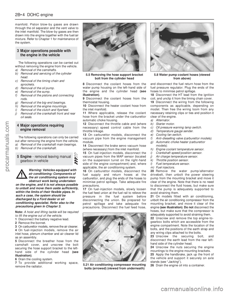
5Disconnect the breather hose from the
camshaft cover, and unscrew the bolt
securing the hose support bracket to the left-
hand side of the cylinder head (see
illustration).
6Drain the cooling system.
7To provide additional working space,
remove the radiator.8Disconnect the coolant hoses from the
water pump housing on the left-hand side of
the engine and the cylinder head (see
illustration).
9Disconnect the coolant hoses from the
thermostat housing.
10Disconnect the heater coolant hose from
the inlet manifold.
11Where applicable, release the coolant
hose from the bracket under the carburettor
automatic choke housing.
12Disconnect the throttle cable and (where
necessary) speed control cable from the
throttle linkage.
13On carburettor models, disconnect the
vacuum pipe from the engine management
module.
14Disconnect the brake servo vacuum hose
(where necessary) from the inlet manifold.
15On fuel-injection models, disconnect the
vacuum pipes from the MAP sensor (located
on the suspension turret on the right-hand
side of the engine compartment) and, where
applicable, the air conditioning system.
16On carburettor models, disconnect the
fuel supply and return hoses at the
carburettor, and plug the ends of the hoses to
minimise petrol spillage. Take adequate fire
precautions.
17On fuel-injection models, slowly loosen
the fuel feed union at the fuel rail to relieve the
pressure in the fuel system before
disconnecting the union. Be prepared for
petrol spillage and take adequate fire
precautions. Disconnect the fuel feed hose,and disconnect the fuel return hose from the
fuel pressure regulator. Plug the ends of the
hoses to minimise petrol spillage.
18Disconnect the HT lead from the ignition
coil, and unclip it from the timing chain cover.
19Disconnect the wiring from the following
components as applicable, depending on
model. Then free the wiring loom from any
necessary retaining clips or ties and position it
clear of the engine.
a)Alternator.
b)Starter motor.
c)Oil pressure warning lamp switch.
d)Temperature gauge sender.
e)Cooling fan switch.
f)Anti-dieselling valve (carburettor models).
g)Automatic choke heater (carburettor
models).
h)Engine coolant temperature sensor.
i)Crankshaft speed/position sensor.
j)Air charge temperature sensor.
k)Throttle position sensor.
l)Fuel temperature sensor.
m)Fuel injectors.
20Remove the water pump/alternator
drivebelt, then unbolt the power steering
pump from the mounting bracket and move it
clear of the engine. Note that there is no need
to disconnect the fluid hoses, but make sure
that the pump is adequately supported to
avoid straining them.
21On models fitted with air conditioning,
unbolt the air conditioning compressor from the
mounting bracket, and move it clear of the
engine (see illustration). Do notdisconnect the
hoses, but make sure that the compressor is
adequately supported to avoid straining them.
22Unscrew and remove the top engine-to-
gearbox bolts which are accessible from the
engine compartment. Note the location of the
bolts, and the positions of the earth strap and
any wiring clips attached to the bolts.
23Unscrew the securing bolt, and
disconnect the earth lead from the rear left-
hand side of the cylinder head.
24Unscrew the nuts securing the engine
mountings to the engine mounting brackets.
25Apply the handbrake, jack up the front of
the vehicle and support it securely on axle
stands (see “Jacking”).
26Drain the engine oil into a container.
5Engine - removal leaving manual
gearbox in vehicle
4Major operations requiring
engine removal
3Major operations possible with
the engine in the vehicle
2B•4DOHCengine
5.5 Removing the hose support bracket
bolt from the cylinder head5.8 Water pump coolant hoses (viewed
from above)
5.21 Air conditioning compressor mounting
bolts (arrowed) (viewed from underneath)
Warning: Vehicles equipped with
air conditioning: Components of
the air conditioning system may
obstruct work being undertaken
on the engine, and it is not always possible
to unbolt and move them aside sufficiently,
within the limits of their flexible pipes. In
such a case, the system should be
discharged by a Ford dealer or air
conditioning specialist. Refer also to the
precautions given in Chapter 3.
procarmanuals.com
Page 49 of 255
Note: Refer to Part A, Section 4 of this Chapter
and to the warning that appears at the start of
Section 5 before proceeding. A hoist and lifting
tackle will be required for this operation.
1Proceed as described in paragraphs 1 to 21
of Section 5.
2Unscrew the securing bolt, and disconnect
the earth lead from the rear left-hand side of
the cylinder head.
3Unscrew the nuts securing the engine
mountings to the engine mounting brackets.
4Jack up the vehicle and support it securely
on axle stands (see “Jacking”). Ensure that
there is enough working room beneath the
vehicle.
5To improve access, disconnect the exhaust
downpipe from the manifold and remove the
exhaust system.
6Drain the engine oil into a suitable container.
7On models fitted with a catalytic converter,
release the securing clips and withdraw the
exhaust heat shield from under the vehicle for
access to the propeller shaft.
8Remove the propeller shaft.
9Where applicable, bend back the locktabs,
then unscrew the two bolts in each case
securing the two anti-roll bar mounting clamps
to the vehicle underbody. Lower the anti-roll
bar as far as possible.
10Proceed as described in paragraphs 30
and 31 of Section 5.
11Support the gearbox with a trolley jack,
using a block of wood between the jack and
the gearbox to spread the load.
12Unscrew the four nuts securing the
gearbox crossmember to the vehicle
underbody. Unscrew the central bolt securing
the crossmember to the gearbox, and remove
the crossmember. Note the position of the
earth strap, where applicable. Recover the
mounting cup, and the exhaust mounting
bracket and heat shield (as applicable).
13Lower the gearbox slightly on the jack,
then remove the circlip, and disconnect the
speedometer drive cable from the gearbox.
14Disconnect the wiring from the reversing
lamp switch, and on models with fuel-injection,
disconnect the wiring from the vehicle speed
sensor mounted in the side of the gearbox.
15Slacken and remove the two bolts and
washers (one either side) securing the gear
linkage support bracket to the gearbox.
16Using a pin punch, drive out the roll pin
securing the gearchange rod to the gear linkage.
17Attach a hoist to the engine lifting brackets
located at the front and rear of the cylinder head,
and slowly take the weight of the engine. Arrange
the lifting tackle so that the engine/gearbox
assembly will assume a steep angle of
approximately 40°to 45°as it is being removed.
18To improve clearance in the engine
compartment when lifting the engine, unboltthe engine mounting brackets from the
cylinder block, and remove them.
19Ensure that the steering wheel is positioned
in the straight-ahead position then, using a dab
of paint or a marker pen, make alignment marks
between the intermediate shaft lower clamp
and steering gear pinion. Slacken and remove
the lower clamp bolt then disconnect the
intermediate shaft from the steering gear.
20Detach the brake lines from the front
suspension crossmember.
21Support the crossmember with a jack (do not
remove the jack from under the gearbox), then
loosen the bolts securing the crossmember to the
underbody. Remove the crossmember securing
bolts, and carefully lower the crossmember to
allow sufficient room for the engine sump to clear
the steering rack and crossmember as the
engine/gearbox assembly is removed.
22Make a final check to ensure that all
relevant wires, pipes and hoses have been
disconnected to facilitate removal of the
engine/gearbox assembly.
23Raise the engine/gearbox, at the same
time lowering the trolley jack which is
supporting the gearbox.
24Place a suitable rod across the vehicle
underbody to support the gear linkage support
bracket whilst the gearbox is removed.
25Tilt the engine/gearbox assembly using
the hoist and the trolley jack, until the
assembly can be lifted from the vehicle. Take
care not to damage surrounding components.
26If the vehicle is to be moved, with the
engine/gearbox assembly removed, temporarily
refit the suspension crossmember and the anti-
roll bar to the underbody, and reconnect the
steering column to the intermediate shaft.
27To separate the engine from the gearbox,
proceed as follows.
28Remove the starter motor.
29Support the engine and gearbox
horizontally on blocks of wood.
30Unscrew the engine-to-gearbox bolts,
noting the locations of the bolts, and the
positions of the earth strap and any wiring clips
attached to the bolts. Recover any shims fitted
between the sump and the gearbox when
removing the lower engine-to-gearbox bolts.
31Unscrew the bolt from the engine adapter
plate.
32Pull the engine and gearbox apart, taking
care not to strain the gearbox input shaft. It
may be necessary to rock the units slightly to
separate them.
Note: Refer to Part A, Section 4 of this
Chapter and to the warning that appears at the
start of Section 5 before proceeding. A
suitable hoist and lifting tackle will be required
for this operation. Any suspected faults in the
automatic transmission should be referred to a
Ford dealer or automatic transmissionspecialist before removal of unit, as the
specialist fault diagnosis equipment is
designed to operate with the transmission in
the vehicle.
1Proceed as described in paragraphs 1 to 21
of Section 5.
2Unscrew the securing bolt, and disconnect
the earth lead from the rear left-hand side of
the cylinder head.
3Unscrew the nuts securing the engine
mountings to the engine mounting brackets.
4Jack up the vehicle and support it securely
on axle stands (see “Jacking”). Ensure that
there is enough working room beneath the
vehicle.
5To improve access, disconnect the exhaust
downpipe from the manifold and remove the
exhaust system .
6Drain the engine oil into a suitable container.
7On models fitted with a catalytic converter,
release the securing clips and withdraw the
exhaust heat shield from under the vehicle for
access to the propeller shaft.
8Remove the propeller shaft.
9Where applicable, bend back the locktabs,
then unscrew the two bolts in each case
securing the two anti-roll bar mounting clamps
to the vehicle underbody. Lower the anti-roll
bar as far as possible.
10Support the transmission with a trolley
jack, using a block of wood between the jack
and the transmission to spread the load.
11Unscrew the four bolts securing the
transmission crossmember to the vehicle
underbody. Unscrew the central bolt securing
the crossmember to the transmission, and
remove the crossmember. Note the position of
the earth strap, where applicable. Recover the
mounting cup, and the exhaust mounting
bracket and heat shield (as applicable).
12Lower the transmission slightly on the jack.
13Unscrew the unions and disconnect the
fluid cooler pipes from the transmission. Plug
the open ends of the pipes and the
transmission to prevent dirt ingress and fluid
leakage. Where applicable, detach the fluid
cooler pipe bracket from the engine mounting
bracket, and move it to one side.
14Remove the two clips securing the
selector rod, and detach the selector rod from
the manual selector lever, and the selector
lever on the transmission.
15Disconnect the wiring from the starter
inhibitor switch, downshift solenoid, lock-up
clutch, reversing lamp switch, and where
applicable, the 3rd/4th gearchange solenoid.
16Remove the securing screw, and
disconnect the speedometer cable (where
fitted) from the transmission extension
housing. Plug the opening in the transmission
to prevent dirt ingress.
17Proceed as described in paragraphs 17 to 26
of Section 7, substituting transmission for
gearbox and ignoring paragraph 24.
18To separate the engine from the
transmission, proceed as follows.
19Remove the starter motor.
20Support the engine and transmission
horizontally on blocks of wood.
8Engine/automatic
transmission assembly -
removal and separation
7Engine/manual gearbox
assembly - removal and
separation
2B•6DOHCengine
procarmanuals.com
Page 54 of 255
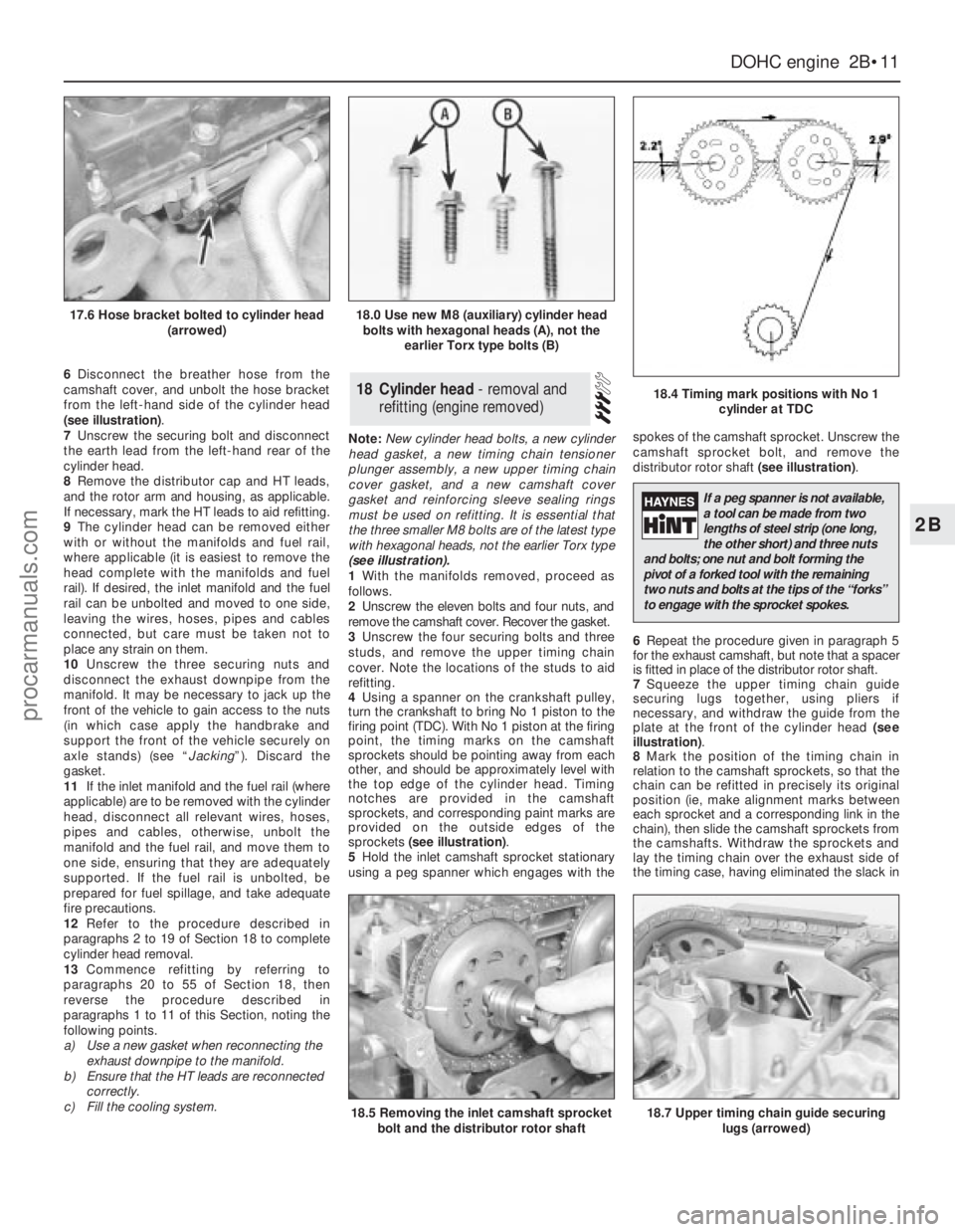
6Disconnect the breather hose from the
camshaft cover, and unbolt the hose bracket
from the left-hand side of the cylinder head
(see illustration).
7Unscrew the securing bolt and disconnect
the earth lead from the left-hand rear of the
cylinder head.
8Remove the distributor cap and HT leads,
and the rotor arm and housing, as applicable.
If necessary, mark the HT leads to aid refitting.
9The cylinder head can be removed either
with or without the manifolds and fuel rail,
where applicable (it is easiest to remove the
head complete with the manifolds and fuel
rail). If desired, the inlet manifold and the fuel
rail can be unbolted and moved to one side,
leaving the wires, hoses, pipes and cables
connected, but care must be taken not to
place any strain on them.
10Unscrew the three securing nuts and
disconnect the exhaust downpipe from the
manifold. It may be necessary to jack up the
front of the vehicle to gain access to the nuts
(in which case apply the handbrake and
support the front of the vehicle securely on
axle stands) (see “Jacking”). Discard the
gasket.
11If the inlet manifold and the fuel rail (where
applicable) are to be removed with the cylinder
head, disconnect all relevant wires, hoses,
pipes and cables, otherwise, unbolt the
manifold and the fuel rail, and move them to
one side, ensuring that they are adequately
supported. If the fuel rail is unbolted, be
prepared for fuel spillage, and take adequate
fire precautions.
12Refer to the procedure described in
paragraphs 2 to 19 of Section 18 to complete
cylinder head removal.
13Commence refitting by referring to
paragraphs 20 to 55 of Section 18, then
reverse the procedure described in
paragraphs 1 to 11 of this Section, noting the
following points.
a)Use a new gasket when reconnecting the
exhaust downpipe to the manifold.
b)Ensure that the HT leads are reconnected
correctly.
c)Fill the cooling system.Note: New cylinder head bolts, a new cylinder
head gasket, a new timing chain tensioner
plunger assembly, a new upper timing chain
cover gasket, and a new camshaft cover
gasket and reinforcing sleeve sealing rings
must be used on refitting. It is essential that
the three smaller M8 bolts are of the latest type
with hexagonal heads, not the earlier Torx type
(see illustration).
1With the manifolds removed, proceed as
follows.
2Unscrew the eleven bolts and four nuts, and
remove the camshaft cover. Recover the gasket.
3Unscrew the four securing bolts and three
studs, and remove the upper timing chain
cover. Note the locations of the studs to aid
refitting.
4Using a spanner on the crankshaft pulley,
turn the crankshaft to bring No 1 piston to the
firing point (TDC). With No 1 piston at the firing
point, the timing marks on the camshaft
sprockets should be pointing away from each
other, and should be approximately level with
the top edge of the cylinder head. Timing
notches are provided in the camshaft
sprockets, and corresponding paint marks are
provided on the outside edges of the
sprockets (see illustration).
5Hold the inlet camshaft sprocket stationary
using a peg spanner which engages with thespokes of the camshaft sprocket. Unscrew the
camshaft sprocket bolt, and remove the
distributor rotor shaft (see illustration).
6Repeat the procedure given in paragraph 5
for the exhaust camshaft, but note that a spacer
is fitted in place of the distributor rotor shaft.
7Squeeze the upper timing chain guide
securing lugs together, using pliers if
necessary, and withdraw the guide from the
plate at the front of the cylinder head (see
illustration).
8Mark the position of the timing chain in
relation to the camshaft sprockets, so that the
chain can be refitted in precisely its original
position (ie, make alignment marks between
each sprocket and a corresponding link in the
chain), then slide the camshaft sprockets from
the camshafts. Withdraw the sprockets and
lay the timing chain over the exhaust side of
the timing case, having eliminated the slack in18Cylinder head - removal and
refitting (engine removed)
DOHCengine 2B•11
2B
17.6 Hose bracket bolted to cylinder head
(arrowed)18.0 Use new M8 (auxiliary) cylinder head
bolts with hexagonal heads (A), not the
earlier Torx type bolts (B)
18.4 Timing mark positions with No 1
cylinder at TDC
18.5 Removing the inlet camshaft sprocket
bolt and the distributor rotor shaft18.7 Upper timing chain guide securing
lugs (arrowed)
If a peg spanner is not available,
a tool can be made from two
lengths of steel strip (one long,
the other short) and three nuts
and bolts; one nut and bolt forming the
pivot of a forked tool with the remaining
two nuts and bolts at the tips of the “forks”
to engage with the sprocket spokes.
procarmanuals.com