1985 FORD GRANADA jacking
[x] Cancel search: jackingPage 149 of 255

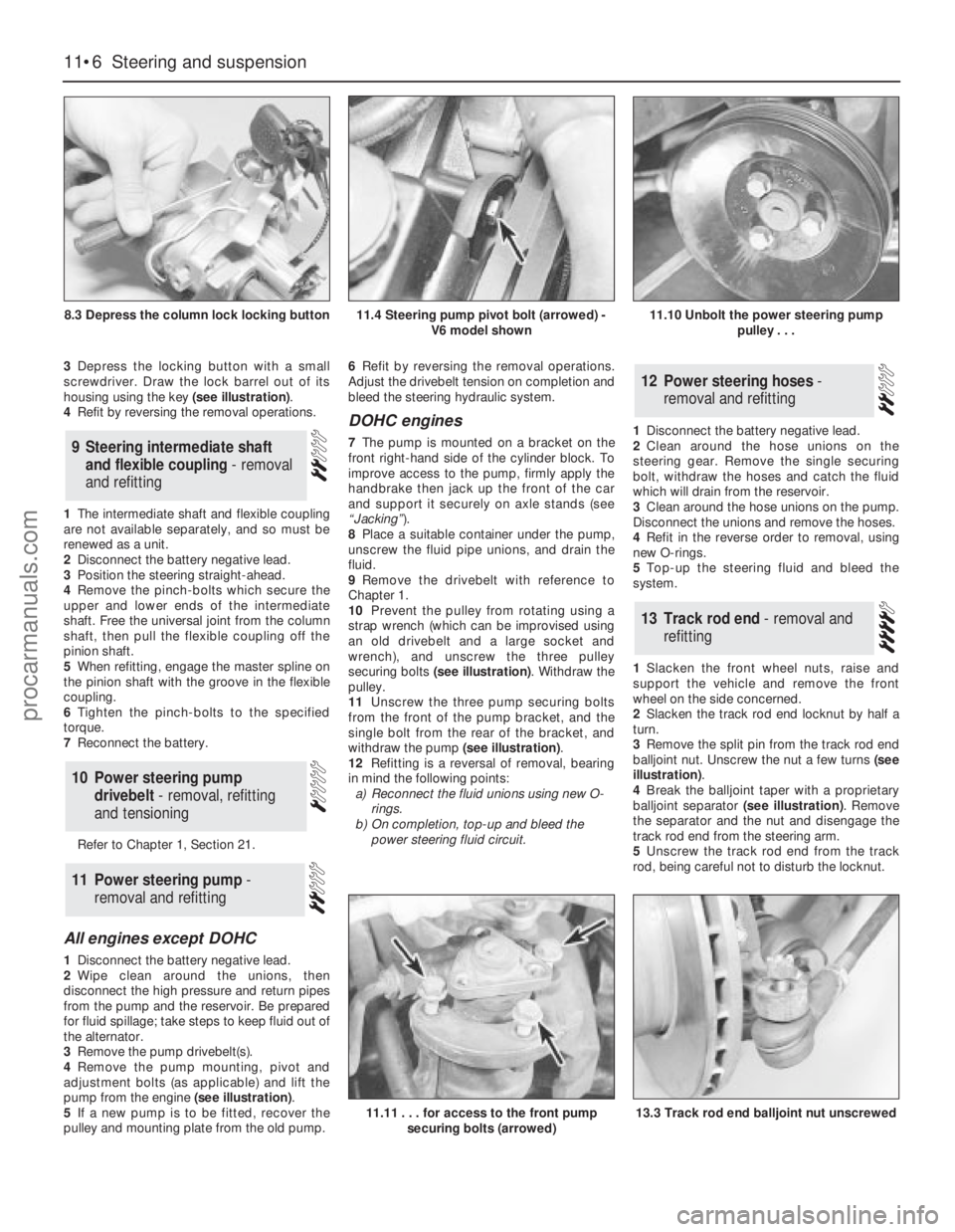
3Depress the locking button with a small
screwdriver. Draw the lock barrel out of its
housing using the key (see illustration).
4Refit by reversing the removal operations.
1The intermediate shaft and flexible coupling
are not available separately, and so must be
renewed as a unit.
2Disconnect the battery negative lead.
3Position the steering straight-ahead.
4Remove the pinch-bolts which secure the
upper and lower ends of the intermediate
shaft. Free the universal joint from the column
shaft, then pull the flexible coupling off the
pinion shaft.
5When refitting, engage the master spline on
the pinion shaft with the groove in the flexible
coupling.
6Tighten the pinch-bolts to the specified
torque.
7Reconnect the battery.
Refer to Chapter 1, Section 21.
All engines except DOHC
1Disconnect the battery negative lead.
2Wipe clean around the unions, then
disconnect the high pressure and return pipes
from the pump and the reservoir. Be prepared
for fluid spillage; take steps to keep fluid out of
the alternator.
3Remove the pump drivebelt(s).
4Remove the pump mounting, pivot and
adjustment bolts (as applicable) and lift the
pump from the engine (see illustration).
5If a new pump is to be fitted, recover the
pulley and mounting plate from the old pump.6Refit by reversing the removal operations.
Adjust the drivebelt tension on completion and
bleed the steering hydraulic system.
DOHC engines
7The pump is mounted on a bracket on the
front right-hand side of the cylinder block. To
improve access to the pump, firmly apply the
handbrake then jack up the front of the car
and support it securely on axle stands (see
“Jacking”).
8Place a suitable container under the pump,
unscrew the fluid pipe unions, and drain the
fluid.
9Remove the drivebelt with reference to
Chapter 1.
10Prevent the pulley from rotating using a
strap wrench (which can be improvised using
an old drivebelt and a large socket and
wrench), and unscrew the three pulley
securing bolts (see illustration). Withdraw the
pulley.
11Unscrew the three pump securing bolts
from the front of the pump bracket, and the
single bolt from the rear of the bracket, and
withdraw the pump (see illustration).
12Refitting is a reversal of removal, bearing
in mind the following points:
a)Reconnect the fluid unions using new O-
rings.
b)On completion, top-up and bleed the
power steering fluid circuit.1Disconnect the battery negative lead.
2Clean around the hose unions on the
steering gear. Remove the single securing
bolt, withdraw the hoses and catch the fluid
which will drain from the reservoir.
3Clean around the hose unions on the pump.
Disconnect the unions and remove the hoses.
4Refit in the reverse order to removal, using
new O-rings.
5Top-up the steering fluid and bleed the
system.
1Slacken the front wheel nuts, raise and
support the vehicle and remove the front
wheel on the side concerned.
2Slacken the track rod end locknut by half a
turn.
3Remove the split pin from the track rod end
balljoint nut. Unscrew the nut a few turns (see
illustration).
4Break the balljoint taper with a proprietary
balljoint separator (see illustration). Remove
the separator and the nut and disengage the
track rod end from the steering arm.
5Unscrew the track rod end from the track
rod, being careful not to disturb the locknut.
13Track rod end - removal and
refitting
12Power steering hoses -
removal and refitting
11Power steering pump -
removal and refitting
10Power steering pump
drivebelt - removal, refitting
and tensioning
9Steering intermediate shaft
and flexible coupling - removal
and refitting
11•6Steering and suspension
8.3 Depress the column lock locking button
11.11 . . . for access to the front pump
securing bolts (arrowed)13.3 Track rod end balljoint nut unscrewed
11.4 Steering pump pivot bolt (arrowed) -
V6 model shown11.10 Unbolt the power steering pump
pulley . . .
procarmanuals.com
Page 152 of 255

1Raise the vehicle on ramps or on a hoist, so
that the weight is still on the wheels.
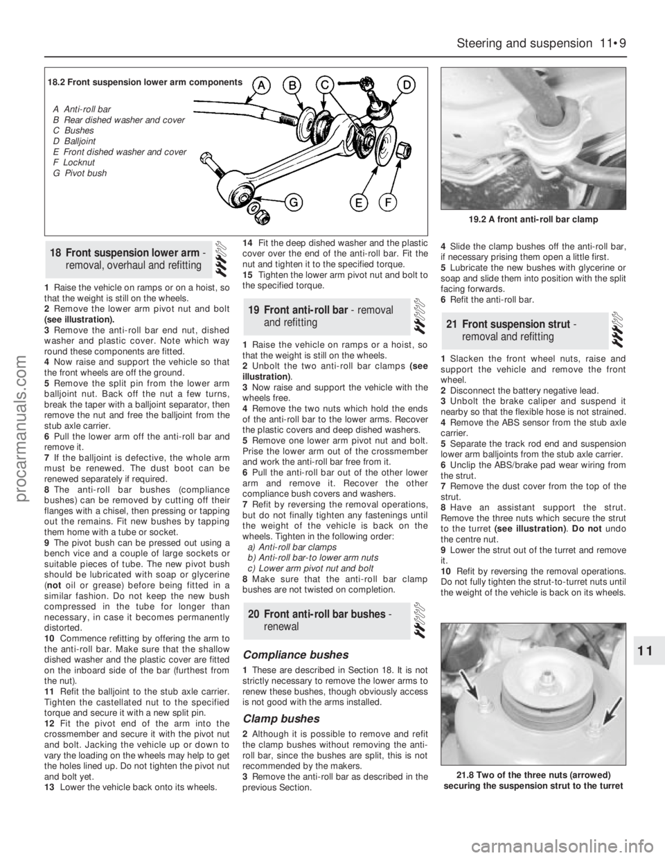
2Remove the lower arm pivot nut and bolt
(see illustration).
3Remove the anti-roll bar end nut, dished
washer and plastic cover. Note which way
round these components are fitted.
4Now raise and support the vehicle so that
the front wheels are off the ground.
5Remove the split pin from the lower arm
balljoint nut. Back off the nut a few turns,
break the taper with a balljoint separator, then
remove the nut and free the balljoint from the
stub axle carrier.
6Pull the lower arm off the anti-roll bar and
remove it.
7If the balljoint is defective, the whole arm
must be renewed. The dust boot can be
renewed separately if required.
8The anti-roll bar bushes (compliance
bushes) can be removed by cutting off their
flanges with a chisel, then pressing or tapping
out the remains. Fit new bushes by tapping
them home with a tube or socket.
9The pivot bush can be pressed out using a
bench vice and a couple of large sockets or
suitable pieces of tube. The new pivot bush
should be lubricated with soap or glycerine
(notoil or grease) before being fitted in a
similar fashion. Do not keep the new bush
compressed in the tube for longer than
necessary, in case it becomes permanently
distorted.
10Commence refitting by offering the arm to
the anti-roll bar. Make sure that the shallow
dished washer and the plastic cover are fitted
on the inboard side of the bar (furthest from
the nut).
11Refit the balljoint to the stub axle carrier.
Tighten the castellated nut to the specified
torque and secure it with a new split pin.
12Fit the pivot end of the arm into the
crossmember and secure it with the pivot nut
and bolt. Jacking the vehicle up or down to
vary the loading on the wheels may help to get
the holes lined up. Do not tighten the pivot nut
and bolt yet.
13Lower the vehicle back onto its wheels.14Fit the deep dished washer and the plastic
cover over the end of the anti-roll bar. Fit the
nut and tighten it to the specified torque.
15Tighten the lower arm pivot nut and bolt to
the specified torque.
1Raise the vehicle on ramps or a hoist, so
that the weight is still on the wheels.
2Unbolt the two anti-roll bar clamps (see
illustration).
3Now raise and support the vehicle with the
wheels free.
4Remove the two nuts which hold the ends
of the anti-roll bar to the lower arms. Recover
the plastic covers and deep dished washers.
5Remove one lower arm pivot nut and bolt.
Prise the lower arm out of the crossmember
and work the anti-roll bar free from it.
6Pull the anti-roll bar out of the other lower
arm and remove it. Recover the other
compliance bush covers and washers.
7Refit by reversing the removal operations,
but do not finally tighten any fastenings until
the weight of the vehicle is back on the
wheels. Tighten in the following order:
a)Anti-roll bar clamps
b)Anti-roll bar-to lower arm nuts
c)Lower arm pivot nut and bolt
8Make sure that the anti-roll bar clamp
bushes are not twisted on completion.
Compliance bushes
1These are described in Section 18. It is not
strictly necessary to remove the lower arms to
renew these bushes, though obviously access
is not good with the arms installed.
Clamp bushes
2Although it is possible to remove and refit
the clamp bushes without removing the anti-
roll bar, since the bushes are split, this is not
recommended by the makers.
3Remove the anti-roll bar as described in the
previous Section.4Slide the clamp bushes off the anti-roll bar,
if necessary prising them open a little first.
5Lubricate the new bushes with glycerine or
soap and slide them into position with the split
facing forwards.
6Refit the anti-roll bar.
1Slacken the front wheel nuts, raise and
support the vehicle and remove the front
wheel.
2Disconnect the battery negative lead.
3Unbolt the brake caliper and suspend it
nearby so that the flexible hose is not strained.
4Remove the ABS sensor from the stub axle
carrier.
5Separate the track rod end and suspension
lower arm balljoints from the stub axle carrier.
6Unclip the ABS/brake pad wear wiring from
the strut.
7Remove the dust cover from the top of the
strut.
8Have an assistant support the strut.
Remove the three nuts which secure the strut
to the turret (see illustration).Do notundo
the centre nut.
9Lower the strut out of the turret and remove
it.
10Refit by reversing the removal operations.
Do not fully tighten the strut-to-turret nuts until
the weight of the vehicle is back on its wheels.
21Front suspension strut -
removal and refitting
20Front anti-roll bar bushes -
renewal
19Front anti-roll bar - removal
and refitting
18Front suspension lower arm -
removal, overhaul and refitting
Steering and suspension 11•9
11
19.2 A front anti-roll bar clamp
21.8 Two of the three nuts (arrowed)
securing the suspension strut to the turret
18.2 Front suspension lower arm components
A Anti-roll bar
B Rear dished washer and cover
C Bushes
D Balljoint
E Front dished washer and cover
F Locknut
G Pivot bush
procarmanuals.com
Page 253 of 255

IND•2
F
Facia panels and trim - 12•12
Fast idle speed adjustment - 4•13
Fault finding- REF•5et seq
Fault-finding - electrical system - 5•3, 13•3
Final drive and driveshafts- 1•15, 9•1et
seq, 11•10, REF•9
Fire - 0•5
Flasher switch and unit - 13•11
Fluid leakage - REF•8
Fluid level checks - 1•6
Flywheel ring gear - 2A•14, 2C•15
Flywheel/driveplate - 2A•9, 2A•16, 2B•15,
2C•11, 2C•17
Foglight - 13•5,13•13
Footbrake - 0•11, 0•12
Footwell lights - 13•8
Fuel and exhaust systems- 0•14, 4•1et seq,
REF•8
Fuel computer components - 13•17
Fuel consumption high - REF•8
Fuel filler lock barrel - 12•7
Fuel filler switch - 13•18
Fuel filter - 1•19, 4•14
Fuel flow sensor - 13•18
Fuel gauge gives false reading - REF•11
Fuel odour - REF•8
Fuel pressure regulator - 4•18
Fuel temperature sensor - 5•12
Fuel trap (carburettor models) - 5•9
Fume or gas intoxication - 0•5
Fumes from exhaust system - REF•8
Fuses - 13•13
G
G (gravity) switch - 10•14
Gaskets - REF•4
Gear linkage - 7A•4
Gear selection problems - REF•8, REF•9
Glossary of technical terms - REF•12
Glovebox light - 13•8
Graphic display module - 13•18
Graphic equaliser - 13•21
Grille - 12•9
H
Handbrake “ON” switch - 13•12
Handbrake - 0•11, 10•11
Handles - 12•6
Hazard warning switch - 13•9, 13•13
HC emissions - 0•14
Headlight - 13•4, 13•6, 13•7, 13•11
Headlining - 12•11
Headphone relay - 13•22
Heated rear window switch - 13•13
Heated seat control switches - 13•13
Heater assembly - 3•7, 3•8, 3•9, 3•10,
13•11, 13•20
High frequency units - 13•22
High pressure hose - 10•10
Hinges - 1•12
Horn - 13•10
Horn emits intermittent or unsatisfactory
sound - REF•11Horn fails to operate - REF•11
Horn inoperative, or unsatisfactory in
operation - REF•11
Horn operates all the time - REF•11
Horn switch plate, slip rings and brushes -
13•10
HT leads - 5•5
HT voltage - 5•3
Hub - 11•11
Hydraulic system seals and hoses - 1•19
Hydraulic unit - 10•8, 10•9, 10•10
Hydrofluoric acid - 0•5
I
Idle mixture - 1•10
Idle speed - 1•10, 4•7, 4•9, 4•11, 4•14, 5•11
Idle speed control valve - 4•15
Idle speed linkage - 1•15
Ignition coil - 5•9
Ignition module - 5•8
Ignition system - 1•17
Ignition timing - 5•7, 5•11
Ignition/no-charge warning light fails to
come on - REF•11
Ignition/no-charge warning light remains
illuminated with engine running - REF•11
Ignition/starter switch - 13•11
Inlet manifold - 1•14, 4•19
Instrument cluster - 13•9, 13•10
Instrument illumination dimmer switch - 13•11
Instrument panel lights - 13•8
Instrument readings inaccurate or erratic -
REF•11
Instruments and electrical equipment - 1•16
Intensive maintenance - 1•6
Interior lights - 13•7
Introduction to the Ford Granada - 0•4
J
Jacking - 0•6
Joint mating faces - REF•4
Joystick fader control - 13•22
Jump starting - 0•10
Jumps out of gear - REF•8
L
Latch locks but will not unlock, or unlocks
but will not lock - REF•11
Leaks - 0•8, 1•10
Lighter - 13•10
Lighting master switch - 13•11
Lights - 13•4, 13•6
Lights inoperative - REF•10
Locknuts, locktabs and washers - REF•4
Locks - 1•12, 12•6, 12•7
Loudspeakers - 13•21, 13•22
Low pressure hose - 10•10
Lower arm - 11•9, 11•12
Lubricant leaks - REF•8
Lubricants and fluids - 1•2
Luggage area light - 13•8
M
Main bearings - 2A•11, 2A•15, 2B•17,
2C•12, 2C•15
Maintenance - bodywork and underframe -
12•1
Maintenance - upholstery and carpets -
12•2
Manifold absolute pressure (MAP) sensor -
5•12
Manifold heater - 5•11
Manual gearbox- 1•11, 2B•6, 2B•7, 7A•1et
seq, REF•8
Manual steering - 11•3
Master cylinder - 10•12
Mirror - 0•11, 12•12, 13•11
Mixture adjustment potentiometer - 4•19
Mixture adjustments - 4•7, 4•9, 4•11, 4•14
Motifs and emblems - 12•10
Motor factors - 0•9
Mountings - 2A•11, 2B•8, 2C•12
N
Needle valve and float - 4•11
Number plate light - 13•5
O
Oil - 1•6, 1•9
Oil filler cap - 1•10
Oil filter - 1•9, 2A•11
Oil leakage from final drive - REF•9
Oil pressure warning light illuminated with
engine running - REF•7
Oil pressure warning switch - 13•12
Oil pump - 2A•10, 2A•12, 2A•16, 2B•16,
2B•17, 2C•11, 2C•14, 2C•17
Oil seals - 2A•10, 2B•15, 2C•12, 9•2, 9•3,
REF•4
On load voltage check - 5•5
Open-circuit - 13•3
Overcooling - REF•7
Overhead console - 12•17
Overheating - REF•7
P
Pads - 1•10, 10•4, 10•5
Parcel shelf - 12•19
Parking light - 13•4
Pedal Travel Sensor (PTS) - 10•14
Pedals - 6•2, 4•6, 10•8
Pierburg 2V carburettor - 4•7, 4•9
Pistons and connecting rods - 2A•11, 2A•13,
2A•15, 2B•17, 2C•12, 2C•14, 2C•16
Pitching and/or rolling around corners, or
during braking - REF•10
Plastic components - 12•3
Poisonous or irrirant substances - 0•5
Power steering - 1•16, 11•3, 11•4, 11•6
Power valve diaphragm - 4•12
Pre-ignition (pinking) or knocking during
acceleration or under load - REF•7
Printed circuit board - 13•20
Propeller shaft- 8•1et seq, REF•9
Pushrods - 2C•13
Index
procarmanuals.com