1985 FORD GRANADA alarm
[x] Cancel search: alarmPage 4 of 255
1•3
1
Maintenance Schedule
Engine oil
SOHC:
With filter . . . . . . . . . . . . . . . . . . . . . . . . . . . . . .3.75 litres (6.6 pints)
DOHC:
With filter . . . . . . . . . . . . . . . . . . . . . . . . . . . . . . .4.5 litres (7.9 pints)
Without filter . . . . . . . . . . . . . . . . . . . . . . . . . . . . .4.0 litres (7.0 pints)
V6:
With filter . . . . . . . . . . . . . . . . . . . . . . . . . . . . . .4.25 litres (7.5 pints)
Cooling system
OHC . . . . . . . . . . . . . . . . . . . . . . . . . . . . . . . . . . . .8.0 litres (14.1 pints)
V6 . . . . . . . . . . . . . . . . . . . . . . . . . . . . . . . . . . . .8.5 litres (15.0 pints)
Fuel tank
All models . . . . . . . . . . . . . . . . . . . . . . . . . . . . .70 litres (15.4 gallons)
Manual gearbox
All models . . . . . . . . . . . . . . . . . . . . . . . . . . . . . .1.25 litres (2.2 pints)
Automatic transmission
All models (from dry) . . . . . . . . . . . . . . . . . . . . . . .8.5 litres (15.0 pints)
Final drive
7 inch crownwheel . . . . . . . . . . . . . . . . . . . . . . . . . .0.9 litres (1.6 pints)
7.5 inch crownwheel . . . . . . . . . . . . . . . . . . . . . . . . .1.3 litres (2.3 pints)
Power steering
OHC . . . . . . . . . . . . . . . . . . . . . . . . . . . . . . . . . . . .0.65 litres (1.1 pints)
V6 . . . . . . . . . . . . . . . . . . . . . . . . . . . . . . . . . . . .0.75 litres (1.3 pints)
Capacities
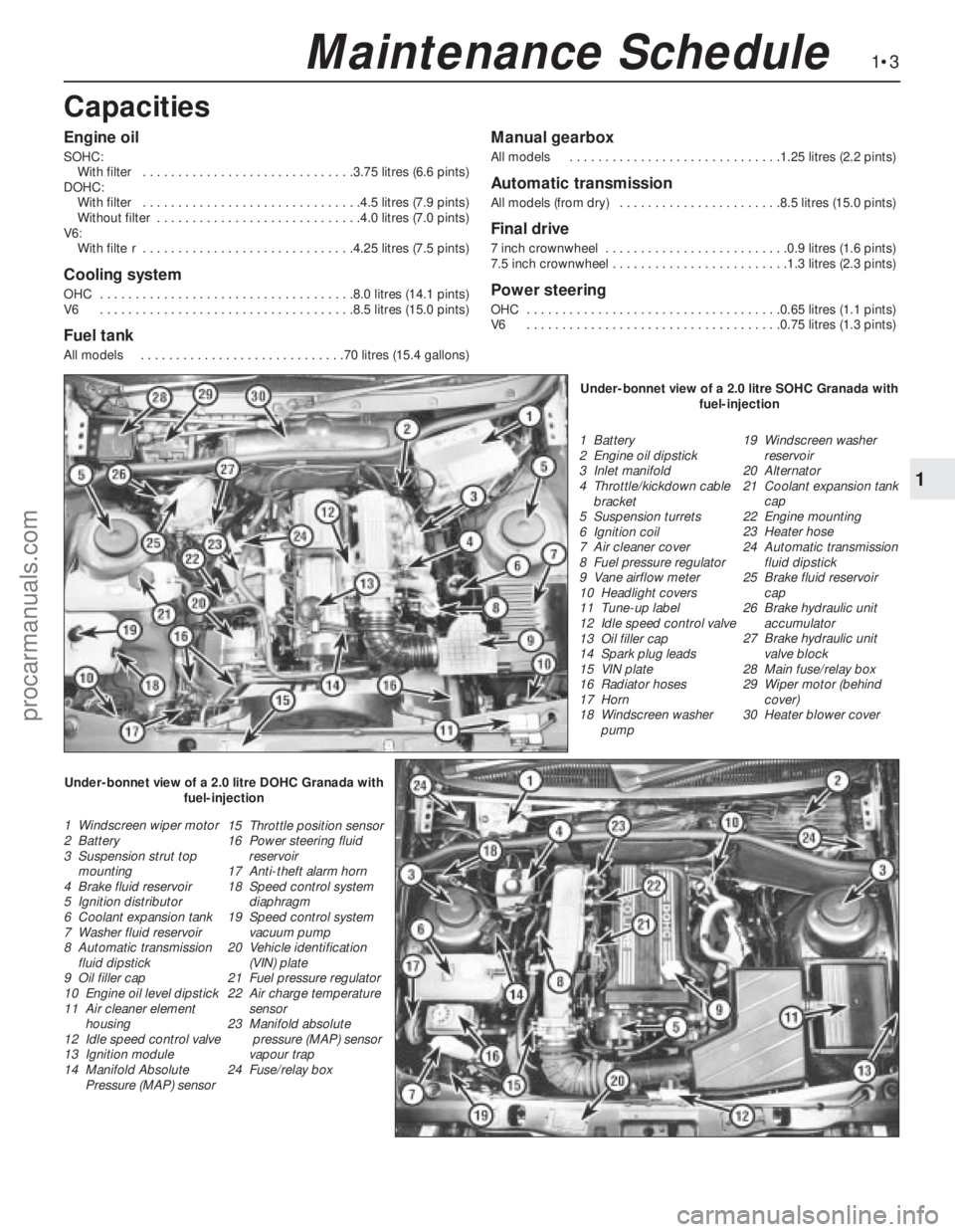
1 Battery
2 Engine oil dipstick
3 Inlet manifold
4 Throttle/kickdown cable
bracket
5 Suspension turrets
6 Ignition coil
7 Air cleaner cover
8 Fuel pressure regulator
9 Vane airflow meter
10 Headlight covers
11 Tune-up label
12 Idle speed control valve
13 Oil filler cap
14 Spark plug leads
15 VIN plate
16 Radiator hoses
17 Horn
18 Windscreen washer
pump19 Windscreen washer
reservoir
20 Alternator
21 Coolant expansion tank
cap
22 Engine mounting
23 Heater hose
24 Automatic transmission
fluid dipstick
25 Brake fluid reservoir
cap
26 Brake hydraulic unit
accumulator
27 Brake hydraulic unit
valve block
28 Main fuse/relay box
29 Wiper motor (behind
cover)
30 Heater blower cover
1 Windscreen wiper motor
2 Battery
3 Suspension strut top
mounting
4 Brake fluid reservoir
5 Ignition distributor
6 Coolant expansion tank
7 Washer fluid reservoir
8 Automatic transmission
fluid dipstick
9 Oil filler cap
10 Engine oil level dipstick
11 Air cleaner element
housing
12 Idle speed control valve
13 Ignition module
14 Manifold Absolute
Pressure (MAP) sensor15 Throttle position sensor
16 Power steering fluid
reservoir
17 Anti-theft alarm horn
18 Speed control system
diaphragm
19 Speed control system
vacuum pump
20 Vehicle identification
(VIN) plate
21 Fuel pressure regulator
22 Air charge temperature
sensor
23 Manifold absolute
pressure (MAP) sensor
vapour trap
24 Fuse/relay boxUnder-bonnet view of a 2.0 litre SOHC Granada with
fuel-injection
Under-bonnet view of a 2.0 litre DOHC Granada with
fuel-injection
procarmanuals.com
Page 171 of 255
12•14Bodywork and fittings
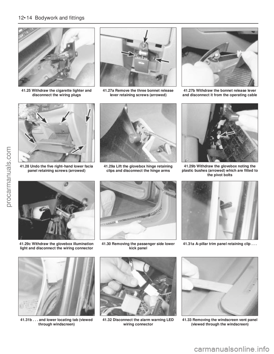
41.25 Withdraw the cigarette lighter and
disconnect the wiring plugs
41.30 Removing the passenger side lower
kick panel
41.29a Lift the glovebox hinge retaining
clips and disconnect the hinge arms41.29b Withdraw the glovebox noting the
plastic bushes (arrowed) which are fitted to
the pivot bolts
41.29c Withdraw the glovebox illumination
light and disconnect the wiring connector
41.28 Undo the five right-hand lower facia
panel retaining screws (arrowed)
41.31a A-pillar trim panel retaining clip . . .
41.31b . . . and lower locating tab (viewed
through windscreen)
41.27a Remove the three bonnet release
lever retaining screws (arrowed)41.27b Withdraw the bonnet release lever
and disconnect it from the operating cable
41.32 Disconnect the alarm warning LED
wiring connector41.33 Removing the windscreen vent panel
(viewed through the windscreen)
procarmanuals.com
Page 172 of 255
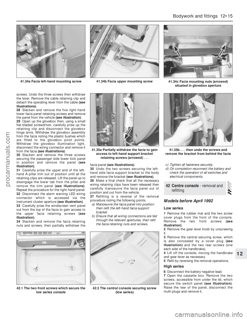
screws. Undo the three screws then withdraw
the lever. Remove the cable retaining clip and
detach the operating lever from the cable (see
illustrations).
28Slacken and remove the five right-hand
lower facia panel retaining screws and remove
the panel from the vehicle (see illustration).
29Open up the glovebox then, using a small
flat-bladed screwdriver, carefully prise up the
retaining clip and disconnect the glovebox
hinge arms. Withdraw the glovebox assembly
from the facia noting the plastic bushes which
are fitted to the glovebox pivot points.
Withdraw the glovebox illumination light,
disconnect the wiring connector and remove it
from the facia (see illustrations).
30Slacken and remove the three screws
securing the passenger side lower kick panel
in position and remove the panel (see
illustration).
31Carefully prise the upper end of the left-
hand A-pillar trim out of position until all the
retaining clips are released. Lift the panel up to
disengage the lower tab from the pillar and
remove the trim panel (see illustrations).
Repeat the procedure for the right-hand panel.
32Disconnect the alarm warning LED wiring
connector which is accessed via the
instrument cluster aperture (see illustration).
33Carefully prise the windscreen vent panel
out from the top of the facia to gain access to
the upper facia retaining screws (see
illustration).
34Slacken and remove the facia retaining
nuts and screws, then partially withdraw thefacia panel (see illustrations).
35Undo the two screws securing the left-
hand side facia support bracket to the body
and remove the bracket (see illustrations).
36Make a final check that all the necessary
wiring retaining clips have been released then
carefully manoeuvre the facia panel out of
position and out from the vehicle.
37Refitting is a reverse of the removal
procedure noting the following points.
a)Manoeuvre the facia panel into position
then refit the left-hand facia support
bracket.
b)Ensure that all wiring connections are fed
through the relevant apertures, then refit
the facia retaining nuts and screws.c)Tighten all fasteners securely.
d)On completion reconnect the battery and
check the operation of all switches and
electrical components.
Models before April 1992
Low series
1Remove the rubber mat and the two screw
cover plugs from the front of the console.
Remove the two front screws (see
illustration).
2Remove the gear lever knob by unscrewing
it.
3Remove the central securing screw, which
is also concealed by a cover plug (see
illustration)and the two rear screws (one
each side of the handbrake).
4Lift off the console, moving the handbrake
and gear lever as necessary.
5Refit by reversing the removal operations.
High series
6Disconnect the battery negative lead.
7Open the cassette box. Remove the two
screws, accessible from under the lid, which
secure the switch panel (see illustration).
Raise the rear of the panel, disconnect the
multi-plugs and remove it.
42Centre console - removal and
refitting
Bodywork and fittings 12•15
12
41.34c Facia mounting nuts (arrowed)
situated in glovebox aperture41.34b Facia upper mounting screw41.34a Facia left-hand mounting screw
41.35a Partially withdraw the facia to gain
access to left-hand support bracket
retaining screws (arrowed) . . .41.35b . . . then undo the screws and
remove the bracket from behind the facia
42.1 The two front screws which secure the
low series console42.3 The central console securing screw
(low series)
procarmanuals.com
Page 178 of 255
Chapter 13
Body electrical system
Anti-theft alarm system components - removal and refitting . . . . . .36
Auxiliary warning system components - testing, removal and
refitting . . . . . . . . . . . . . . . . . . . . . . . . . . . . . . . . . . . . . . . . . . . . .27
Central locking motor - removal and refitting . . . . . . . . . . . . . . . . . .17
Cigarette lighter - removal and refitting . . . . . . . . . . . . . . . . . . . . . .10
Clock - removal and refitting . . . . . . . . . . . . . . . . . . . . . . . . . . . . . . .9
Electrical fault-finding - general information . . . . . . . . . . . . . . . . . . .2
Exterior lights - bulb renewal . . . . . . . . . . . . . . . . . . . . . . . . . . . . . . .3
Exterior light units - removal and refitting . . . . . . . . . . . . . . . . . . . . .4
Fuel computer components - removal and refitting . . . . . . . . . . . . .26
Fuses, relays and control units - removal and refitting . . . . . . . . . .16
General information . . . . . . . . . . . . . . . . . . . . . . . . . . . . . . . . . . . . . .1
Headlight beam alignment . . . . . . . . . . . . . . . . . . . . . . . . . . . . . . . . .5
Heater blower motor - removal and refitting . . . . . . . . . . . . . . . . . .29
Horn - removal and refitting . . . . . . . . . . . . . . . . . . . . . . . . . . . . . . .11
Horn switch plate, slip rings and brushes - removal and refitting . .12
Ignition/starter switch - removal and refitting . . . . . . . . . . . . . . . . . .14
Instrument cluster - dismantling and reassembly . . . . . . . . . . . . . . .8
Instrument cluster - removal and refitting . . . . . . . . . . . . . . . . . . . . .7
Interior lights - bulb renewal . . . . . . . . . . . . . . . . . . . . . . . . . . . . . . . .6Joystick fader control - removal and refitting . . . . . . . . . . . . . . . . . .33
Loudspeakers (original equipment) - removal and refitting . . . . . . .31
Radio aerial pre-amplifier (original equipment) - removal and
refitting . . . . . . . . . . . . . . . . . . . . . . . . . . . . . . . . . . . . . . . . . . . . .32
Radio or radio/cassette player (original equipment) - removal and
refitting . . . . . . . . . . . . . . . . . . . . . . . . . . . . . . . . . . . . . . . . . . . . .30
Rear entertainment console - removal and refitting . . . . . . . . . . . . .34
Rear headphone relay - removal and refitting . . . . . . . . . . . . . . . . .35
Rear window wiper motor - removal and refitting . . . . . . . . . . . . . .24
Seat adjusting motors - removal and refitting . . . . . . . . . . . . . . . . .19
Seat heating elements - removal and refitting . . . . . . . . . . . . . . . . .13
Sliding roof motor - removal and refitting . . . . . . . . . . . . . . . . . . . .20
Speed control system components - removal and refitting . . . . . . .28
Speedometer sender unit - removal and refitting . . . . . . . . . . . . . . .21
Switches - removal and refitting . . . . . . . . . . . . . . . . . . . . . . . . . . . .15
Window operating motor - removal and refitting . . . . . . . . . . . . . . .18
Windscreen, rear window and headlight washer components -
removal and refitting . . . . . . . . . . . . . . . . . . . . . . . . . . . . . . . . . . .25
Windscreen wiper motor and linkage - removal and refitting . . . . .23
Wiper arms and blades - removal and refitting . . . . . . . . . . . . . . . .22
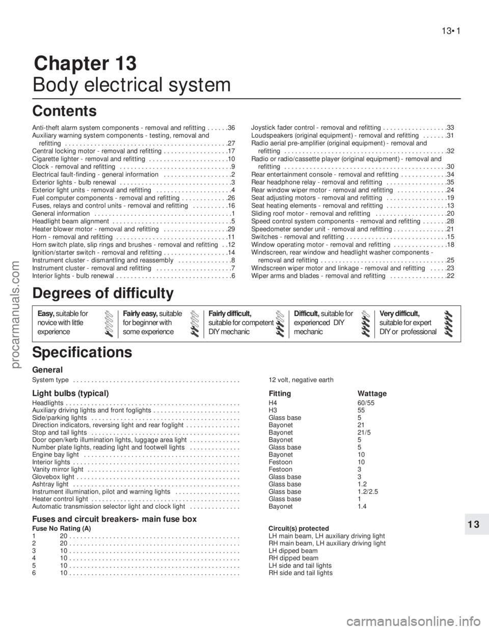
General
System type . . . . . . . . . . . . . . . . . . . . . . . . . . . . . . . . . . . . . . . . . . . . . . 12 volt, negative earth
Light bulbs (typical)Fitting Wattage
Headlights . . . . . . . . . . . . . . . . . . . . . . . . . . . . . . . . . . . . . . . . . . . . . . . . H4 60/55
Auxiliary driving lights and front foglights . . . . . . . . . . . . . . . . . . . . . . . . H3 55
Side/parking lights . . . . . . . . . . . . . . . . . . . . . . . . . . . . . . . . . . . . . . . . . Glass base 5
Direction indicators, reversing light and rear foglight . . . . . . . . . . . . . . . Bayonet 21
Stop and tail lights . . . . . . . . . . . . . . . . . . . . . . . . . . . . . . . . . . . . . . . . . Bayonet 21/5
Door open/kerb illumination lights, luggage area light . . . . . . . . . . . . . . Bayonet 5
Number plate lights, reading light and footwell lights . . . . . . . . . . . . . . Glass base 5
Engine bay light . . . . . . . . . . . . . . . . . . . . . . . . . . . . . . . . . . . . . . . . . . . Bayonet 10
Interior lights . . . . . . . . . . . . . . . . . . . . . . . . . . . . . . . . . . . . . . . . . . . . . . Festoon 10
Vanity mirror light . . . . . . . . . . . . . . . . . . . . . . . . . . . . . . . . . . . . . . . . . . Festoon 3
Glovebox light . . . . . . . . . . . . . . . . . . . . . . . . . . . . . . . . . . . . . . . . . . . . . Glass base 3
Ashtray light . . . . . . . . . . . . . . . . . . . . . . . . . . . . . . . . . . . . . . . . . . . . . . Glass base 1.2
Instrument illumination, pilot and warning lights . . . . . . . . . . . . . . . . . . Glass base 1.2/2.5
Heater control light . . . . . . . . . . . . . . . . . . . . . . . . . . . . . . . . . . . . . . . . . Glass base 1
Automatic transmission selector light and clock light . . . . . . . . . . . . . . Bayonet 1.4
Fuses and circuit breakers- main fuse box
Fuse No Rating (A) Circuit(s) protected
1 20 . . . . . . . . . . . . . . . . . . . . . . . . . . . . . . . . . . . . . . . . . . . . . . . LH main beam, LH auxiliary driving light
2 20 . . . . . . . . . . . . . . . . . . . . . . . . . . . . . . . . . . . . . . . . . . . . . . . RH main beam, LH auxiliary driving light
3 10 . . . . . . . . . . . . . . . . . . . . . . . . . . . . . . . . . . . . . . . . . . . . . . . LH dipped beam
4 10 . . . . . . . . . . . . . . . . . . . . . . . . . . . . . . . . . . . . . . . . . . . . . . . RH dipped beam
5 10 . . . . . . . . . . . . . . . . . . . . . . . . . . . . . . . . . . . . . . . . . . . . . . . LH side and tail lights
6 10 . . . . . . . . . . . . . . . . . . . . . . . . . . . . . . . . . . . . . . . . . . . . . . . RH side and tail lights
13•1
Easy,suitable for
novice with little
experienceFairly easy,suitable
for beginner with
some experienceFairly difficult,
suitable for competent
DIY mechanicDifficult,suitable for
experienced DIY
mechanicVery difficult,
suitable for expert
DIY or professional
Degrees of difficulty
Specifications Contents
13
procarmanuals.com
Page 179 of 255
13•2Body electrical system
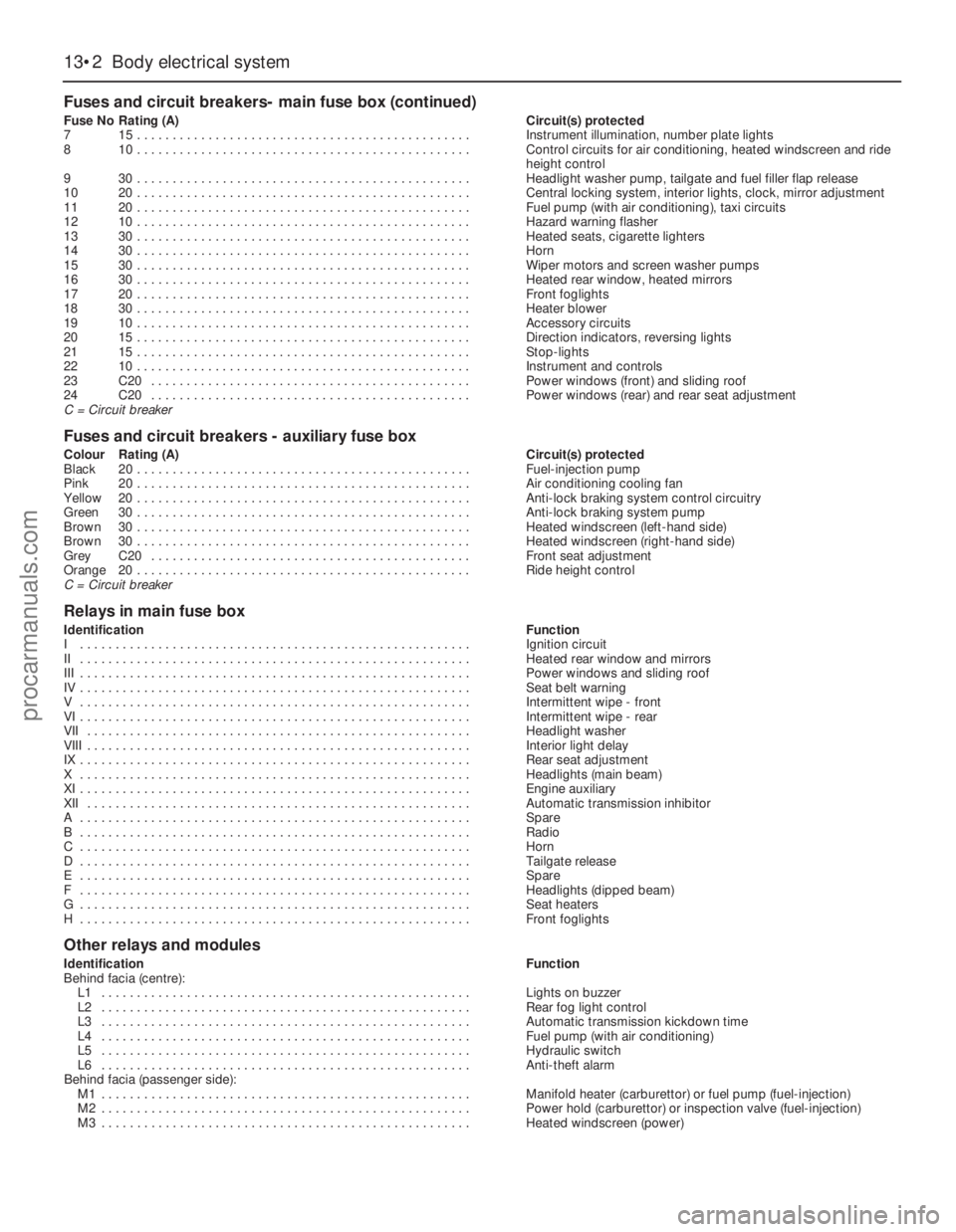
Fuses and circuit breakers- main fuse box (continued)
Fuse NoRating (A)Circuit(s) protected
715 . . . . . . . . . . . . . . . . . . . . . . . . . . . . . . . . . . . . . . . . . . . . . . .Instrument illumination, number plate lights
810 . . . . . . . . . . . . . . . . . . . . . . . . . . . . . . . . . . . . . . . . . . . . . . .Control circuits for air conditioning, heated windscreen and ride
height control
930 . . . . . . . . . . . . . . . . . . . . . . . . . . . . . . . . . . . . . . . . . . . . . . .Headlight washer pump, tailgate and fuel filler flap release
1020 . . . . . . . . . . . . . . . . . . . . . . . . . . . . . . . . . . . . . . . . . . . . . . .Central locking system, interior lights, clock, mirror adjustment
1120 . . . . . . . . . . . . . . . . . . . . . . . . . . . . . . . . . . . . . . . . . . . . . . .Fuel pump (with air conditioning), taxi circuits
1210 . . . . . . . . . . . . . . . . . . . . . . . . . . . . . . . . . . . . . . . . . . . . . . .Hazard warning flasher
1330 . . . . . . . . . . . . . . . . . . . . . . . . . . . . . . . . . . . . . . . . . . . . . . .Heated seats, cigarette lighters
1430 . . . . . . . . . . . . . . . . . . . . . . . . . . . . . . . . . . . . . . . . . . . . . . .Horn
1530 . . . . . . . . . . . . . . . . . . . . . . . . . . . . . . . . . . . . . . . . . . . . . . .Wiper motors and screen washer pumps
1630 . . . . . . . . . . . . . . . . . . . . . . . . . . . . . . . . . . . . . . . . . . . . . . .Heated rear window, heated mirrors
1720 . . . . . . . . . . . . . . . . . . . . . . . . . . . . . . . . . . . . . . . . . . . . . . .Front foglights
1830 . . . . . . . . . . . . . . . . . . . . . . . . . . . . . . . . . . . . . . . . . . . . . . .Heater blower
1910 . . . . . . . . . . . . . . . . . . . . . . . . . . . . . . . . . . . . . . . . . . . . . . .Accessory circuits
2015 . . . . . . . . . . . . . . . . . . . . . . . . . . . . . . . . . . . . . . . . . . . . . . .Direction indicators, reversing lights
2115 . . . . . . . . . . . . . . . . . . . . . . . . . . . . . . . . . . . . . . . . . . . . . . .Stop-lights
2210 . . . . . . . . . . . . . . . . . . . . . . . . . . . . . . . . . . . . . . . . . . . . . . .Instrument and controls
23C20 . . . . . . . . . . . . . . . . . . . . . . . . . . . . . . . . . . . . . . . . . . . . .Power windows (front) and sliding roof
24C20 . . . . . . . . . . . . . . . . . . . . . . . . . . . . . . . . . . . . . . . . . . . . .Power windows (rear) and rear seat adjustment
C = Circuit breaker
Fuses and circuit breakers - auxiliary fuse box
Colour Rating (A)Circuit(s) protected
Black20 . . . . . . . . . . . . . . . . . . . . . . . . . . . . . . . . . . . . . . . . . . . . . . .Fuel-injection pump
Pink20 . . . . . . . . . . . . . . . . . . . . . . . . . . . . . . . . . . . . . . . . . . . . . . .Air conditioning cooling fan
Yellow20 . . . . . . . . . . . . . . . . . . . . . . . . . . . . . . . . . . . . . . . . . . . . . . .Anti-lock braking system control circuitry
Green30 . . . . . . . . . . . . . . . . . . . . . . . . . . . . . . . . . . . . . . . . . . . . . . .Anti-lock braking system pump
Brown30 . . . . . . . . . . . . . . . . . . . . . . . . . . . . . . . . . . . . . . . . . . . . . . .Heated windscreen (left-hand side)
Brown30 . . . . . . . . . . . . . . . . . . . . . . . . . . . . . . . . . . . . . . . . . . . . . . .Heated windscreen (right-hand side)
GreyC20 . . . . . . . . . . . . . . . . . . . . . . . . . . . . . . . . . . . . . . . . . . . . .Front seat adjustment
Orange20 . . . . . . . . . . . . . . . . . . . . . . . . . . . . . . . . . . . . . . . . . . . . . . .Ride height control
C = Circuit breaker
Relays in main fuse box
IdentificationFunction
I . . . . . . . . . . . . . . . . . . . . . . . . . . . . . . . . . . . . . . . . . . . . . . . . . . . . . . .Ignition circuit
II . . . . . . . . . . . . . . . . . . . . . . . . . . . . . . . . . . . . . . . . . . . . . . . . . . . . . . .Heated rear window and mirrors
III . . . . . . . . . . . . . . . . . . . . . . . . . . . . . . . . . . . . . . . . . . . . . . . . . . . . . . .Power windows and sliding roof
IV . . . . . . . . . . . . . . . . . . . . . . . . . . . . . . . . . . . . . . . . . . . . . . . . . . . . . . .Seat belt warning
V . . . . . . . . . . . . . . . . . . . . . . . . . . . . . . . . . . . . . . . . . . . . . . . . . . . . . . .Intermittent wipe - front
VI . . . . . . . . . . . . . . . . . . . . . . . . . . . . . . . . . . . . . . . . . . . . . . . . . . . . . . .Intermittent wipe - rear
VII . . . . . . . . . . . . . . . . . . . . . . . . . . . . . . . . . . . . . . . . . . . . . . . . . . . . . .Headlight washer
VIII . . . . . . . . . . . . . . . . . . . . . . . . . . . . . . . . . . . . . . . . . . . . . . . . . . . . . .Interior light delay
IX . . . . . . . . . . . . . . . . . . . . . . . . . . . . . . . . . . . . . . . . . . . . . . . . . . . . . . .Rear seat adjustment
X . . . . . . . . . . . . . . . . . . . . . . . . . . . . . . . . . . . . . . . . . . . . . . . . . . . . . . .Headlights (main beam)
XI . . . . . . . . . . . . . . . . . . . . . . . . . . . . . . . . . . . . . . . . . . . . . . . . . . . . . . .Engine auxiliary
XII . . . . . . . . . . . . . . . . . . . . . . . . . . . . . . . . . . . . . . . . . . . . . . . . . . . . . .Automatic transmission inhibitor
A . . . . . . . . . . . . . . . . . . . . . . . . . . . . . . . . . . . . . . . . . . . . . . . . . . . . . . .Spare
B . . . . . . . . . . . . . . . . . . . . . . . . . . . . . . . . . . . . . . . . . . . . . . . . . . . . . . .Radio
C . . . . . . . . . . . . . . . . . . . . . . . . . . . . . . . . . . . . . . . . . . . . . . . . . . . . . . .Horn
D . . . . . . . . . . . . . . . . . . . . . . . . . . . . . . . . . . . . . . . . . . . . . . . . . . . . . . .Tailgate release
E . . . . . . . . . . . . . . . . . . . . . . . . . . . . . . . . . . . . . . . . . . . . . . . . . . . . . . .Spare
F . . . . . . . . . . . . . . . . . . . . . . . . . . . . . . . . . . . . . . . . . . . . . . . . . . . . . . .Headlights (dipped beam)
G . . . . . . . . . . . . . . . . . . . . . . . . . . . . . . . . . . . . . . . . . . . . . . . . . . . . . . .Seat heaters
H . . . . . . . . . . . . . . . . . . . . . . . . . . . . . . . . . . . . . . . . . . . . . . . . . . . . . . .Front foglights
Other relays and modules
IdentificationFunction
Behind facia (centre):
L1 . . . . . . . . . . . . . . . . . . . . . . . . . . . . . . . . . . . . . . . . . . . . . . . . . . . .Lights on buzzer
L2 . . . . . . . . . . . . . . . . . . . . . . . . . . . . . . . . . . . . . . . . . . . . . . . . . . . .Rear fog light control
L3 . . . . . . . . . . . . . . . . . . . . . . . . . . . . . . . . . . . . . . . . . . . . . . . . . . . .Automatic transmission kickdown time
L4 . . . . . . . . . . . . . . . . . . . . . . . . . . . . . . . . . . . . . . . . . . . . . . . . . . . .Fuel pump (with air conditioning)
L5 . . . . . . . . . . . . . . . . . . . . . . . . . . . . . . . . . . . . . . . . . . . . . . . . . . . .Hydraulic switch
L6 . . . . . . . . . . . . . . . . . . . . . . . . . . . . . . . . . . . . . . . . . . . . . . . . . . . .Anti-theft alarm
Behind facia (passenger side):
M1 . . . . . . . . . . . . . . . . . . . . . . . . . . . . . . . . . . . . . . . . . . . . . . . . . . . .Manifold heater (carburettor) or fuel pump (fuel-injection)
M2 . . . . . . . . . . . . . . . . . . . . . . . . . . . . . . . . . . . . . . . . . . . . . . . . . . . .Power hold (carburettor) or inspection valve (fuel-injection)
M3 . . . . . . . . . . . . . . . . . . . . . . . . . . . . . . . . . . . . . . . . . . . . . . . . . . . .Heated windscreen (power)
procarmanuals.com
Page 191 of 255
13•14Body electrical system
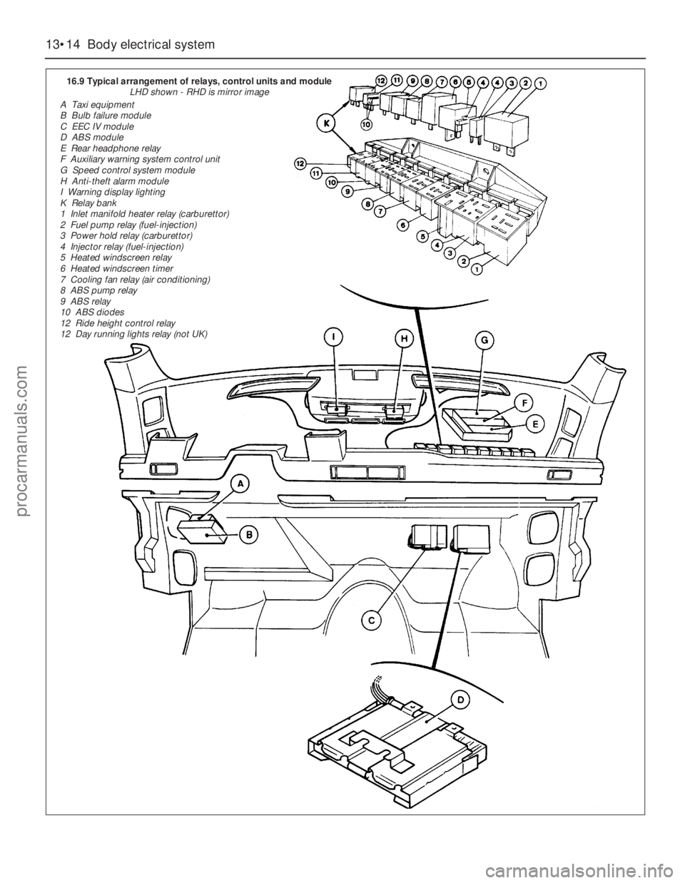
16.9 Typical arrangement of relays, control units and module
LHD shown - RHD is mirror image
A Taxi equipment
B Bulb failure module
C EEC IV module
D ABS module
E Rear headphone relay
F Auxiliary warning system control unit
G Speed control system module
H Anti-theft alarm module
I Warning display lighting
K Relay bank
1 Inlet manifold heater relay (carburettor)
2 Fuel pump relay (fuel-injection)
3 Power hold relay (carburettor)
4 Injector relay (fuel-injection)
5 Heated windscreen relay
6 Heated windscreen timer
7 Cooling fan relay (air conditioning)
8 ABS pump relay
9 ABS relay
10 ABS diodes
12 Ride height control relay
12 Day running lights relay (not UK)
procarmanuals.com
Page 199 of 255
High frequency units
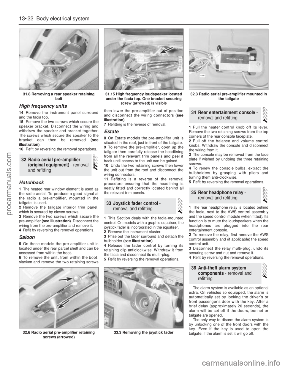
14Remove the instrument panel surround
and the facia top.
15Remove the two screws which secure the
speaker bracket. Disconnect the wiring and
withdraw the speaker and bracket together.
The screws which secure the speaker to the
bracket can then be removed (see
illustration).
16Refit by reversing the removal operations.
Hatchback
1The heated rear window element is used as
the radio aerial. To produce a good signal at
the radio a pre-amplifier, mounted in the
tailgate, is used.
2Remove the tailgate interior trim panel,
which is secured by eleven screws.
3Remove the two screws which secure the
pre-amplifier (see illustration). Disconnect the
wiring from the pre-amplifier and remove it.
4Refit by reversing the removal operations.
Saloon
5On these models the pre-amplifier unit is
located under the rear parcel shelf and can be
accessed from within the boot.
6To remove the unit, from within the boot,
slacken and remove the two retaining screwsthen lower the pre-amplifier out of position
and disconnect the wiring connectors (see
illustration).
7Refitting is the reverse of removal.
Estate
8On Estate models the pre-amplifier unit is
situated in the roof, just in front of the tailgate.
9To remove the pre-amplifier, open up the
tailgate then carefully release the headlining
from all the relevant trim panels and peel it
back until access to the unit can be gained.
10Undo the two retaining screws then lower
the unit out from the roof and disconnect the
wiring connectors.
11Refitting is a reverse of the removal
procedure ensuring that the headlining is
neatly fitted and correctly located behind all
the relevant trim panels.
1This Section deals with the facia-mounted
control. On models with a graphic equaliser, the
joystick fader is incorporated in the equaliser.
2Remove the instrument cluster.
3Prise out the fader surround and detach the
bulbholder (see illustration).
4Release the fader control by turning its
retaining clip anticlockwise. Withdraw it from
the facia and disconnect its multi-plug.
5Refit by reversing the removal operations.1Pull the heater control knob off its lever.
Remove the two retaining screws from the top
corners of the rear console faceplate.
2Pull off the balance and volume control
knobs. Withdraw the console and disconnect
the wiring from it.
3The console may be removed from the face
plate if wished by undoing the three retaining
screws.
4To renew the console bulbs, extract the
bulbholders by grasping with pliers and
turning them anti-clockwise.
5Refit by reversing the removal operations.
1The rear headphone relay is located behind
the facia, next to the AWS control assembly
and the speed control module (when fitted). Its
function is to mute the loudspeakers when the
headphones are plugged into the rear
entertainment console.
2To remove the relay, first remove the AWS
control assembly and (if applicable) the speed
control unit.
3Disconnect the relay multi-plug, undo its
securing screw and nut and remove it.
4Refit by reversing the removal operations.
The alarm system is available as an optional
extra. On vehicles so equipped, the alarm is
automatically set by locking the driver’s or
front passenger’s door with the key. After a
brief delay (approximately 20 seconds), the
alarm will be set off if the doors, bonnet or
tailgate are opened.
The only way to disarm the alarm system is
by unlocking one of the front doors with the
key. Even if the key is used to open the
tailgate, if the alarm is set it will go off.
36Anti-theft alarm system
components - removal and
refitting
35Rear headphone relay -
removal and refitting
34Rear entertainment console -
removal and refitting
33Joystick fader control -
removal and refitting
32Radio aerial pre-amplifier
(original equipment) - removal
and refitting
13•22Body electrical system
31.8 Removing a rear speaker retaining
bolt
32.6 Radio aerial pre-amplifier retaining
screws (arrowed)33.3 Removing the joystick fader
31.15 High frequency loudspeaker located
under the facia top. One bracket securing
screw (arrowed) is visible32.3 Radio aerial pre-amplifier mounted in
the tailgate
procarmanuals.com
Page 200 of 255
The components of the alarm system are a
control module, tripping switches, activating
switches, an alarm horn and a signal buzzer.
The control module is located behind the
facia. It determines whether the alarm is set or
not, monitors the tripping switches and the
ignition circuit, and limits the duration of the
alarm to 30 seconds. This last item is a legal
requirement. The control module also
operates the signal buzzer to tell the driver
that the alarm is set, and controls the activator
delay.
The tripping switches on the doors and
tailgate are the same as those used for “open
door” warnings in the AWS. The bonnet switch
is peculiar to the alarm system.
The activating switches are fitted to the
front door lock barrels, where they are
activated by a lug on the end of the barrel.
They only make contact momentarily as the
lock is operated.
The alarm horn is mounted next to the
battery. Both the horn and its leads are
claimed to be inaccessible without opening
the bonnet. The signal buzzer is also mounted
under the bonnet.
No service, repair or component renewal
procedures have been published for the alarmsystem components on earlier models. Any
problems arising which cannot be dealt with
by component substitution should therefore
be referred to a Ford dealer.
Ultrasonic sensor
1Disconnect the battery negative terminal.
2Prise out the retaining screw trim cap from
the centre of the sensor then slacken and
remove the retaining screws and lower the
sensor away from the headlining,
disconnecting the wiring plug as it becomes
accessible.
3Refitting is the reverse of the removal
procedure.
Anti-theft alarm module (models
from April 1992)
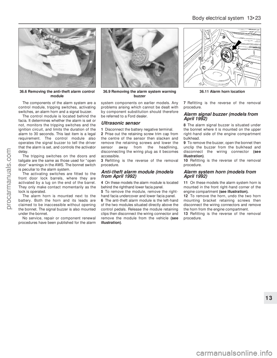
4On these models the alarm module is located
behind the righthand lower facia panel.
5To remove the module, remove the right-
hand facia undercover and lower facia panel.
6The anti-theft alarm module is the left-hand
of the two modules situated directly above the
control pedals. Release the module retaining
clips then disconnect the wiring connector and
remove the module from the vehicle (see
illustration).7Refitting is the reverse of the removal
procedure.
Alarm signal buzzer (models from
April 1992)
8The alarm signal buzzer is situated under
the bonnet where it is mounted on the upper
right-hand side of the engine compartment
bulkhead.
9To remove the buzzer, open the bonnet then
unclip the buzzer from the bulkhead and
disconnect the wiring connector (see
illustration).
10Refitting is the reverse of the removal
procedure.
Alarm system horn (models from
April 1992)
11On these models the alarm system horn is
mounted in the front right-hand corner of the
engine compartment (see illustration).
12To remove the horn, undo the two horn
mounting bracket retaining screws then
disconnect the wiring connectors and remove
the horn from the engine compartment.
13Refitting is the reverse of the removal
procedure.
Body electrical system 13•23
13
36.6 Removing the anti-theft alarm control
module36.9 Removing the alarm system warning
buzzer36.11 Alarm horn location
procarmanuals.com