1985 FORD GRANADA jacking
[x] Cancel search: jackingPage 72 of 255
from the top of the engine mounting brackets
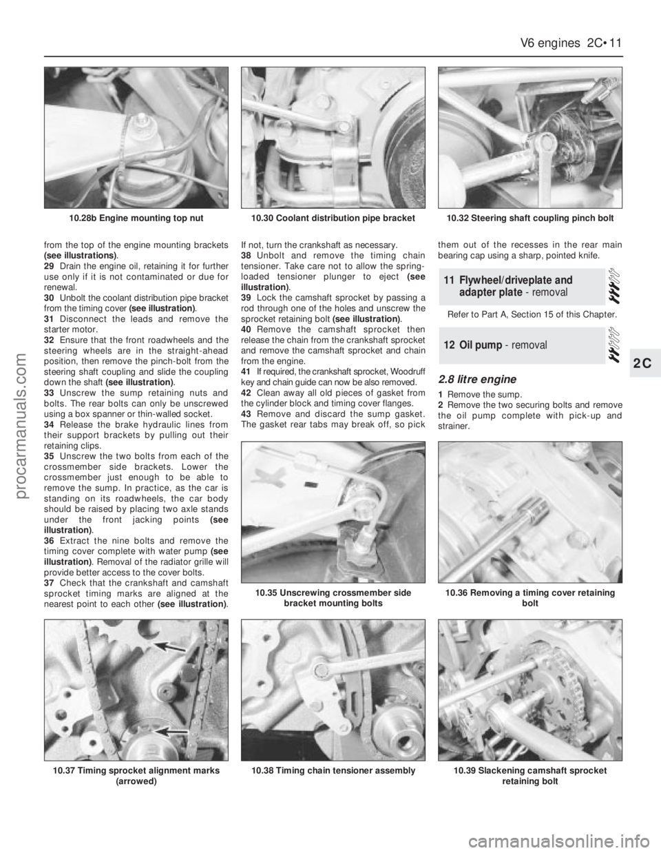
(see illustrations).
29Drain the engine oil, retaining it for further
use only if it is not contaminated or due for
renewal.
30Unbolt the coolant distribution pipe bracket
from the timing cover (see illustration).
31Disconnect the leads and remove the
starter motor.
32Ensure that the front roadwheels and the
steering wheels are in the straight-ahead
position, then remove the pinch-bolt from the
steering shaft coupling and slide the coupling
down the shaft (see illustration).
33Unscrew the sump retaining nuts and
bolts. The rear bolts can only be unscrewed
using a box spanner or thin-walled socket.
34Release the brake hydraulic lines from
their support brackets by pulling out their
retaining clips.
35Unscrew the two bolts from each of the
crossmember side brackets. Lower the
crossmember just enough to be able to
remove the sump. In practice, as the car is
standing on its roadwheels, the car body
should be raised by placing two axle stands
under the front jacking points (see
illustration).
36Extract the nine bolts and remove the
timing cover complete with water pump (see
illustration). Removal of the radiator grille will
provide better access to the cover bolts.
37Check that the crankshaft and camshaft
sprocket timing marks are aligned at the
nearest point to each other (see illustration).If not, turn the crankshaft as necessary.
38Unbolt and remove the timing chain
tensioner. Take care not to allow the spring-
loaded tensioner plunger to eject (see
illustration).
39Lock the camshaft sprocket by passing a
rod through one of the holes and unscrew the
sprocket retaining bolt (see illustration).
40Remove the camshaft sprocket then
release the chain from the crankshaft sprocket
and remove the camshaft sprocket and chain
from the engine.
41If required, the crankshaft sprocket, Woodruff
key and chain guide can now be also removed.
42Clean away all old pieces of gasket from
the cylinder block and timing cover flanges.
43Remove and discard the sump gasket.
The gasket rear tabs may break off, so pickthem out of the recesses in the rear main
bearing cap using a sharp, pointed knife.
Refer to Part A, Section 15 of this Chapter.
2.8 litre engine
1Remove the sump.
2Remove the two securing bolts and remove
the oil pump complete with pick-up and
strainer.
12Oil pump - removal
11Flywheel/driveplate and
adapter plate - removal
V6 engines 2C•11
2C
10.28b Engine mounting top nut10.30 Coolant distribution pipe bracket10.32 Steering shaft coupling pinch bolt
10.37 Timing sprocket alignment marks
(arrowed)
10.36 Removing a timing cover retaining
bolt10.35 Unscrewing crossmember side
bracket mounting bolts
10.38 Timing chain tensioner assembly10.39 Slackening camshaft sprocket
retaining bolt
procarmanuals.com
Page 80 of 255
29Fit the sump and the retaining nuts and
bolts. Tighten them progressively in two stages.
30Oil the lip of the timing cover oil seal and
the contact surface of the crankshaft damper.
31Fit the damper to the crankshaft, being
careful not to dislodge the Woodruff key. Draw
the damper into position using the retaining
bolt and washer.
32Remove the bolt and apply sealant to the
faces of the washer. Refit the bolt and washer
then jam the starter gear ring teeth and tighten
the bolt to the specified torque.
33Refit the crankshaft pulley and tighten the
retaining bolts to the specified torque.
34Refit the crossmember side brackets and
brake pipes.
35Reconnect the engine mountings and
remove the engine hoist or axle stands (see
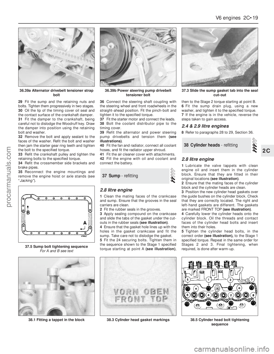
“Jacking”).36Connect the steering shaft coupling with
the steering wheel and front roadwheels in the
straight-ahead position. Fit the pinch-bolt and
tighten it to the specified torque.
37Fit the starter motor and connect the leads.
38Bolt the coolant distributor pipe to the
timing cover.
39Refit the alternator and power steering
pump drivebelts and tension them (see
illustrations).
40Fit the fan and radiator, connect all coolant
hoses, and fit the radiator upper shroud.
41Fit the air cleaner cover with attachments.
42Fill the engine with oil and coolant and
connect the battery.
2.8 litre engine
1Clean the mating faces of the crankcase
and sump. Ensure that the grooves in the seal
carriers are clean.
2Fit the rubber seals in the grooves.
3Apply sealing compound on the crankcase
and slide the tabs of the gasket under the cut-
outs in the rubber seals (see illustration).
4Ensure that the gasket hole lines up with the
holes in the gasket crankcase and fit the
sump. Take care not to dislodge the gasket.
5Fit the 24 securing bolts. Tighten them in
the sequence shown to the Stage 1 specified
torque starting at point A (see illustration),then to the Stage 2 torque starting at point B.
6Fit the sump drain plug, using a new
washer, and tighten it to the specified torque.
7If the engine is in the vehicle, reverse the
steps taken to gain access.
2.4 & 2.9 litre engines
8Refer to paragraphs 28 to 29, Section 36.
2.8 litre engine
1Lubricate the valve tappets with clean
engine oil and insert them in the cylinder
block. Ensure that they are fitted in their
original locations (see illustration).
2Ensure that the mating faces of the cylinder
block and the cylinder heads are clean.
3Position the new cylinder head gaskets over
the guide bushes on the cylinder block. Check
that they are correctly located. The right and
left-hand gaskets are different. The gaskets
are marked FRONT TOP (see illustration).
4Carefully lower the cylinder heads onto the
cylinder block. Oil the threads and contact
faces of the cylinder head bolts and insert
them into their holes.
5Tighten the cylinder head bolts, in the
correct order(see illustration),to the Stage 1
specified torque. Repeat in the same order for
Stages 2 and 3. Final tightening, when
required, is done after warm-up.
38Cylinder heads - refitting
37Sump - refitting
V6 engines 2C•19
2C
36.39a Alternator drivebelt tensioner strap
bolt36.39b Power steering pump drivebelt
tensioner bolt37.3 Slide the sump gasket tab into the seal
cut-out
38.1 Fitting a tappet in the block
37.5 Sump bolt tightening sequence
For A and B see text
38.3 Cylinder head gasket markings38.5 Cylinder head bolt tightening
sequence
procarmanuals.com
Page 88 of 255
V6 engines
17The thermostat is removed in the course
of water pump removal.
1A rough test of the thermostat may be made
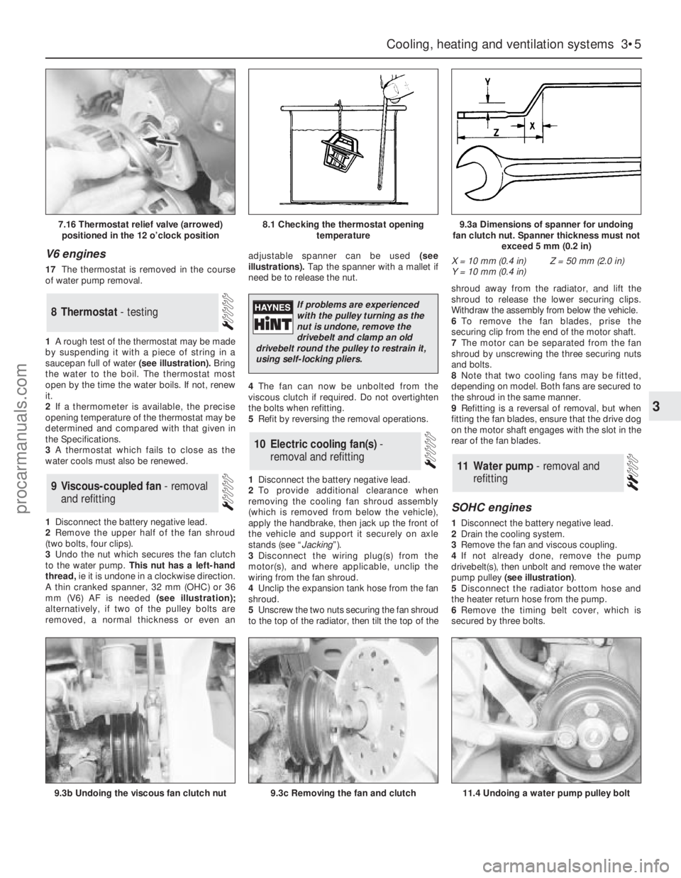
by suspending it with a piece of string in a
saucepan full of water(see illustration).Bring
the water to the boil. The thermostat most
open by the time the water boils. If not, renew
it.
2If a thermometer is available, the precise
opening temperature of the thermostat may be
determined and compared with that given in
the Specifications.
3A thermostat which fails to close as the
water cools must also be renewed.
1Disconnect the battery negative lead.
2Remove the upper half of the fan shroud
(two bolts, four clips).
3Undo the nut which secures the fan clutch
to the water pump.This nut has a left-hand
thread, ie it is undone in a clockwise direction.
A thin cranked spanner, 32 mm (OHC) or 36
mm (V6) AF is needed(see illustration);
alternatively, if two of the pulley bolts are
removed, a normal thickness or even anadjustable spanner can be used (see
illustrations). Tap the spanner with a mallet if
need be to release the nut.
4The fan can now be unbolted from the
viscous clutch if required. Do not overtighten
the bolts when refitting.
5Refit by reversing the removal operations.
1Disconnect the battery negative lead.
2To provide additional clearance when
removing the cooling fan shroud assembly
(which is removed from below the vehicle),
apply the handbrake, then jack up the front of
the vehicle and support it securely on axle
stands (see “Jacking”).
3Disconnect the wiring plug(s) from the
motor(s), and where applicable, unclip the
wiring from the fan shroud.
4Unclip the expansion tank hose from the fan
shroud.
5Unscrew the two nuts securing the fan shroud
to the top of the radiator, then tilt the top of theshroud away from the radiator, and lift the
shroud to release the lower securing clips.
Withdraw the assembly from below the vehicle.
6To remove the fan blades, prise the
securing clip from the end of the motor shaft.
7The motor can be separated from the fan
shroud by unscrewing the three securing nuts
and bolts.
8Note that two cooling fans may be fitted,
depending on model. Both fans are secured to
the shroud in the same manner.
9Refitting is a reversal of removal, but when
fitting the fan blades, ensure that the drive dog
on the motor shaft engages with the slot in the
rear of the fan blades.
SOHC engines
1Disconnect the battery negative lead.
2Drain the cooling system.
3Remove the fan and viscous coupling.
4If not already done, remove the pump
drivebelt(s), then unbolt and remove the water
pump pulley (see illustration).
5Disconnect the radiator bottom hose and
the heater return hose from the pump.
6Remove the timing belt cover, which is
secured by three bolts.
11Water pump - removal and
refitting
10Electric cooling fan(s) -
removal and refitting
9Viscous-coupled fan - removal
and refitting
8Thermostat - testing
Cooling, heating and ventilation systems 3•5
3
7.16 Thermostat relief valve (arrowed)
positioned in the 12 o’clock position8.1 Checking the thermostat opening
temperature9.3a Dimensions of spanner for undoing
fan clutch nut. Spanner thickness must not
exceed 5 mm (0.2 in)
9.3b Undoing the viscous fan clutch nut9.3c Removing the fan and clutch11.4 Undoing a water pump pulley bolt
X = 10 mm (0.4 in)
Y = 10 mm (0.4 in)Z = 50 mm (2.0 in)
If problems are experienced
with the pulley turning as the
nut is undone, remove the
drivebelt and clamp an old
drivebelt round the pulley to restrain it,
using self-locking pliers.
procarmanuals.com
Page 115 of 255
DOHC carburettor engine
8This procedure is essentially as described
above, noting the following points:
a)Note the plastic bush which is fitted to the
rear manifold stud. This must be removed
before the gasket can be withdrawn.
b)On refitting ensure that the mating
surfaces are clean and dry and fit new
gaskets.
c)Apply a thin coat of anti-seize compound
to the manifold studs to aid future
removal.
d)Tighten the manifold nuts to the specified
torque settings.
DOHC fuel-injection engine
9Disconnect the battery negative lead.
10Disconnect the wiring plug from the idle
speed control valve at the front of the plenum
chamber.
11Loosen the clamp, and detach the air inlet
hose from the air inlet tubing.
12Unscrew the securing nut, and release the
air inlet tube from the bracket on the engine
compartment front panel.
13Release the air cleaner lid securing clips,
then lift away the air inlet tube, plenum
chamber and air cleaner lid as an assembly,
disconnecting the breather hose from the air
inlet tube.
14On models fitted with a catalytic
converter, disconnect the exhaust gas oxygen
sensor wiring plug.
15Unscrew the securing nuts and disconnect
the exhaust downpipe from the manifold.
Recover the gasket. Support the exhaust
downpipe from underneath the vehicle (eg
with an axle stand) to avoid placing
unnecessary strain on the exhaust system.
16Unscrew the six securing nuts, and lift the
manifold from the cylinder head. Recover the
gasket.
17Refitting is a reversal of removal, bearing
in mind the following points.
a)Ensure that all mating faces are clean, and
use a new gasket.
b)Tighten the manifold securing nuts and
the downpipe securing nuts progressively
to the specified torque (where given).
SOHC and 2.8 litre V6 engines
1Periodically inspect the exhaust system for
freedom from corrosion and security of
mountings. Large holes will be obvious; small
holes may be found more easily by letting the
engine idle and partly obstructing the tailpipe
with a wad of cloth.
2Check the condition of the rubber
mountings by applying downward pressure on
the exhaust system and observing the
mountings for splits or cracks. Renew
deteriorated mountings.
3The exhaust systems fitted in production
have fewer sections than those available for
repair. Repair sections may be fitted to
production systems by cutting at the
appropriate point.
4The production exhaust systems are made
of aluminised and stainless steel. Repair
systems are available to the same standard, or
in standard quality (SQ) painted mild steel.
5It is recommended that the whole exhaust
system be removed even if only part requires
renewal, since separation of old joints, cutting
pipes etc is much easier away from the
vehicle. Proceed as follows.
6Disconnect the battery negative lead. Raise
and support the vehicle.
7Unbolt the manifold-to-downpipe flanged
joint(s).
8On V6 models, unbolt the left-hand front
silencer mounting.
9Release any earth straps.
10With the help of an assistant, unhook the
system from its mountings and remove it.
11Renew sections as necessary. Apply
exhaust jointing compound to sliding and
flanged joints, but do not tighten their clamps
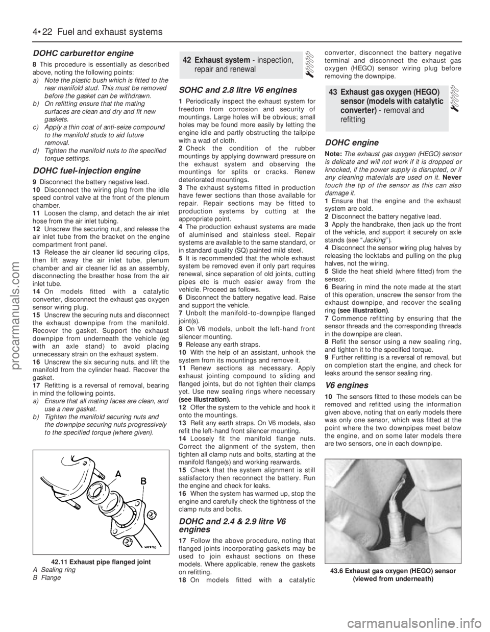
yet. Use new sealing rings where necessary
(see illustration).
12Offer the system to the vehicle and hook it
onto the mountings.
13Refit any earth straps. On V6 models, also
refit the left-hand front silencer mounting.
14Loosely fit the manifold flange nuts.
Correct the alignment of the system, then
tighten all clamp nuts and bolts, starting at the
manifold flange(s) and working rearwards.
15Check that the system alignment is still
satisfactory then reconnect the battery. Run
the engine and check for leaks.
16When the system has warmed up, stop the
engine and carefully check the tightness of the
clamp nuts and bolts.
DOHC and 2.4 & 2.9 litre V6
engines
17Follow the above procedure, noting that
flanged joints incorporating gaskets may be
used to join exhaust sections on these
models. Where applicable, renew the gaskets
on refitting.
18On models fitted with a catalyticconverter, disconnect the battery negative
terminal and disconnect the exhaust gas
oxygen (HEGO) sensor wiring plug before
removing the downpipe.
DOHC engine
Note: The exhaust gas oxygen (HEGO) sensor
is delicate and will not work if it is dropped or
knocked, if the power supply is disrupted, or if
any cleaning materials are used on it. Never
touch the tip of the sensor as this can also
damage it.
1Ensure that the engine and the exhaust
system are cold.
2Disconnect the battery negative lead.
3Apply the handbrake, then jack up the front
of the vehicle, and support it securely on axle
stands (see “Jacking”).
4Disconnect the sensor wiring plug halves by
releasing the locktabs and pulling on the plug
halves, not the wiring.
5Slide the heat shield (where fitted) from the
sensor.
6Bearing in mind the note made at the start
of this operation, unscrew the sensor from the
exhaust downpipe, and recover the sealing
ring (see illustration).
7Commence refitting by ensuring that the
sensor threads and the corresponding threads
in the downpipe are clean.
8Refit the sensor using a new sealing ring,
and tighten it to the specified torque.
9Further refitting is a reversal of removal, but
on completion start the engine, and check for
leaks around the sensor sealing ring.
V6 engines
10The sensors fitted to these models can be
removed and refitted using the information
given above, noting that on early models there
was only one sensor, which was fitted at the
point where the two downpipes meet below
the engine, and on some later models there
are two sensors, one in each downpipe.
43Exhaust gas oxygen (HEGO)
sensor (models with catalytic
converter) - removal and
refitting
42Exhaust system - inspection,
repair and renewal
4•22Fuel and exhaust systems
43.6 Exhaust gas oxygen (HEGO) sensor
(viewed from underneath)
42.11 Exhaust pipe flanged joint
A Sealing ring
B Flange
procarmanuals.com
Page 116 of 255
Models up to July 1990
1The carbon canister is situated in the engine
compartment where it is mounted onto the
right-hand valance next to the suspension
strut mounting.
2To remove the canister first disconnect the
battery negative terminal. If necessary, undo
the two coolant expansion tank retaining
screws and position the tank clear of the
canister to improve access.
3Disconnect the vacuum hose from the top
of the canister.
4Slacken and remove the mounting bolt and
withdraw the canister from the engine
compartment.
5Refitting is a reverse of the removal
procedure.
Models from July 1990
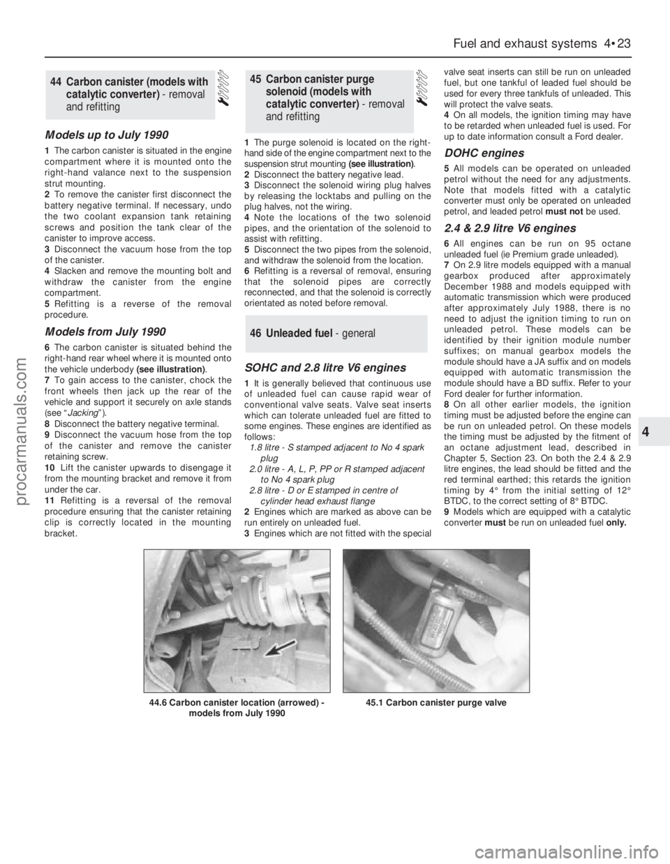
6The carbon canister is situated behind the
right-hand rear wheel where it is mounted onto
the vehicle underbody (see illustration).
7To gain access to the canister, chock the
front wheels then jack up the rear of the
vehicle and support it securely on axle stands
(see “Jacking”).
8Disconnect the battery negative terminal.
9Disconnect the vacuum hose from the top
of the canister and remove the canister
retaining screw.
10Lift the canister upwards to disengage it
from the mounting bracket and remove it from
under the car.
11Refitting is a reversal of the removal
procedure ensuring that the canister retaining
clip is correctly located in the mounting
bracket.1The purge solenoid is located on the right-
hand side of the engine compartment next to the
suspension strut mounting (see illustration).
2Disconnect the battery negative lead.
3Disconnect the solenoid wiring plug halves
by releasing the locktabs and pulling on the
plug halves, not the wiring.
4Note the locations of the two solenoid
pipes, and the orientation of the solenoid to
assist with refitting.
5Disconnect the two pipes from the solenoid,
and withdraw the solenoid from the location.
6Refitting is a reversal of removal, ensuring
that the solenoid pipes are correctly
reconnected, and that the solenoid is correctly
orientated as noted before removal.
SOHC and 2.8 litre V6 engines
1It is generally believed that continuous use
of unleaded fuel can cause rapid wear of
conventional valve seats. Valve seat inserts
which can tolerate unleaded fuel are fitted to
some engines. These engines are identified as
follows:
1.8 litre - S stamped adjacent to No 4 spark
plug
2.0 litre - A, L, P, PP or R stamped adjacent
to No 4 spark plug
2.8 litre - D or E stamped in centre of
cylinder head exhaust flange
2Engines which are marked as above can be
run entirely on unleaded fuel.
3Engines which are not fitted with the specialvalve seat inserts can still be run on unleaded
fuel, but one tankful of leaded fuel should be
used for every three tankfuls of unleaded. This
will protect the valve seats.
4On all models, the ignition timing may have
to be retarded when unleaded fuel is used. For
up to date information consult a Ford dealer.
DOHC engines
5All models can be operated on unleaded
petrol without the need for any adjustments.
Note that models fitted with a catalytic
converter must only be operated on unleaded
petrol, and leaded petrol must notbe used.
2.4 & 2.9 litre V6 engines
6All engines can be run on 95 octane
unleaded fuel (ie Premium grade unleaded).
7On 2.9 litre models equipped with a manual
gearbox produced after approximately
December 1988 and models equipped with
automatic transmission which were produced
after approximately July 1988, there is no
need to adjust the ignition timing to run on
unleaded petrol. These models can be
identified by their ignition module number
suffixes; on manual gearbox models the
module should have a JA suffix and on models
equipped with automatic transmission the
module should have a BD suffix. Refer to your
Ford dealer for further information.
8On all other earlier models, the ignition
timing must be adjusted before the engine can
be run on unleaded petrol. On these models
the timing must be adjusted by the fitment of
an octane adjustment lead, described in
Chapter 5, Section 23. On both the 2.4 & 2.9
litre engines, the lead should be fitted and the
red terminal earthed; this retards the ignition
timing by 4°from the initial setting of 12°
BTDC, to the correct setting of 8°BTDC.
9Models which are equipped with a catalytic
converter must be run on unleaded fuel only.
46Unleaded fuel - general
45Carbon canister purge
solenoid (models with
catalytic converter) - removal
and refitting44Carbon canister (models with
catalytic converter) - removal
and refitting
Fuel and exhaust systems 4•23
4
44.6 Carbon canister location (arrowed) -
models from July 199045.1 Carbon canister purge valve
procarmanuals.com
Page 128 of 255
2Disconnect the battery negative lead.
3Drain the cooling system (Chapter 3). Save
the coolant if it is fit for re-use.
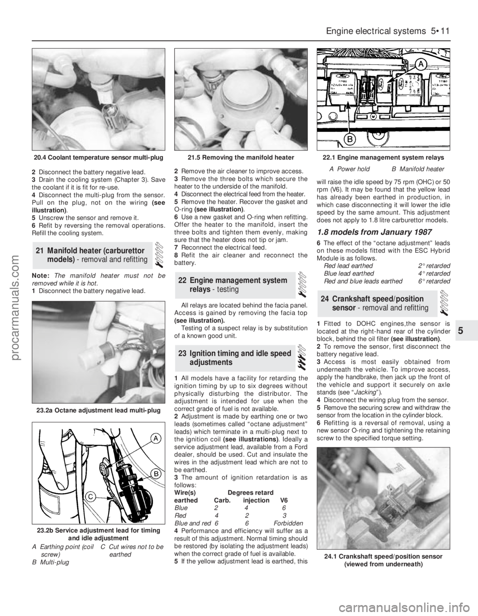
4Disconnect the multi-plug from the sensor.
Pull on the plug, not on the wiring (see
illustration).
5Unscrew the sensor and remove it.
6Refit by reversing the removal operations.
Refill the cooling system.
Note: The manifold heater must not be
removed while it is hot.
1Disconnect the battery negative lead. 2Remove the air cleaner to improve access.
3Remove the three bolts which secure the
heater to the underside of the manifold.
4Disconnect the electrical feed from the heater.
5Remove the heater. Recover the gasket and
O-ring (see illustration).
6Use a new gasket and O-ring when refitting.
Offer the heater to the manifold, insert the
three bolts and tighten them evenly, making
sure that the heater does not tip or jam.
7Reconnect the electrical feed.
8Refit the air cleaner and reconnect the
battery.
All relays are located behind the facia panel.
Access is gained by removing the facia top
(see illustration).
Testing of a suspect relay is by substitution
of a known good unit.
1All models have a facility for retarding the
ignition timing by up to six degrees without
physically disturbing the distributor. The
adjustment is intended for use when the
correct grade of fuel is not available.
2Adjustment is made by earthing one or two
leads (sometimes called “octane adjustment”
leads) which terminate in a multi-plug next to
the ignition coil (see illustrations). Ideally a
service adjustment lead, available from a Ford
dealer, should be used. Cut and insulate the
wires in the adjustment lead which are not to
be earthed.
3The amount of ignition retardation is as
follows:
Wire(s) Degrees retard
earthed Carb. injection V6
Blue 2 4 6
Red 4 2 3
Blue and red 6 6 Forbidden
4Performance and efficiency will suffer as a
result of this adjustment. Normal timing should
be restored (by isolating the adjustment leads)
when the correct grade of fuel is available.
5If the yellow adjustment lead is earthed, thiswill raise the idle speed by 75 rpm (OHC) or 50
rpm (V6). It may be found that the yellow lead
has already been earthed in production, in
which case disconnecting it will lower the idle
speed by the same amount. This adjustment
does not apply to 1.8 litre carburettor models.
1.8 models from January 1987
6The effect of the “octane adjustment” leads
on these models fitted with the ESC Hybrid
Module is as follows.
Red lead earthed2°retarded
Blue lead earthed4°retarded
Red and blue leads earthed6°retarded
1Fitted to DOHC engines,the sensor is
located at the right-hand rear of the cylinder
block, behind the oil filter (see illustration).
2To remove the sensor, first disconnect the
battery negative lead.
3Access is most easily obtained from
underneath the vehicle. To improve access,
apply the handbrake, then jack up the front of
the vehicle and support it securely on axle
stands (see “Jacking”).
4Disconnect the wiring plug from the sensor.
5Remove the securing screw and withdraw the
sensor from the location in the cylinder block.
6Refitting is a reversal of removal, using a
new sensor O-ring and tightening the retaining
screw to the specified torque setting.
24Crankshaft speed/position
sensor - removal and refitting
23Ignition timing and idle speed
adjustments
22Engine management system
relays - testing
21Manifold heater (carburettor
models) - removal and refitting
Engine electrical systems 5•11
5
20.4 Coolant temperature sensor multi-plug21.5 Removing the manifold heater22.1 Engine management system relays
A Power holdB Manifold heater
23.2a Octane adjustment lead multi-plug
23.2b Service adjustment lead for timing
and idle adjustment
A Earthing point (coil
screw)
B Multi-plugC Cut wires not to be
earthed
24.1 Crankshaft speed/position sensor
(viewed from underneath)
procarmanuals.com
Page 129 of 255
1The sensor is located in the upper section of
the inlet manifold (DOHC fuel-injection
engines) or the side of the plenum chamber
(V6 engines).
2To remove the sensor, first disconnect the
battery negative lead.
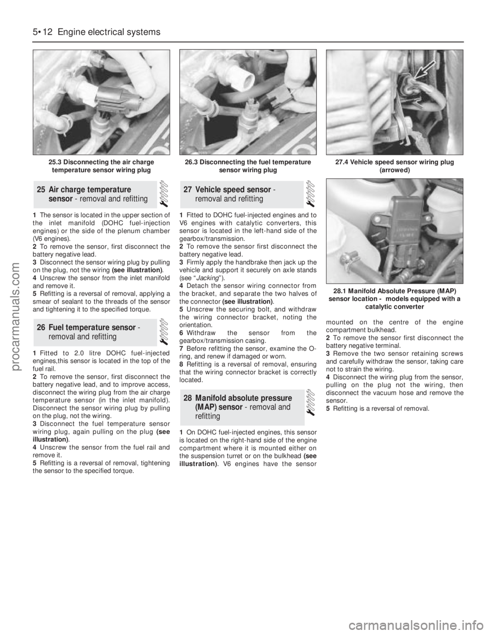
3Disconnect the sensor wiring plug by pulling
on the plug, not the wiring (see illustration).
4Unscrew the sensor from the inlet manifold
and remove it.
5Refitting is a reversal of removal, applying a
smear of sealant to the threads of the sensor
and tightening it to the specified torque.
1Fitted to 2.0 litre DOHC fuel-injected
engines,this sensor is located in the top of the
fuel rail.
2To remove the sensor, first disconnect the
battery negative lead, and to improve access,
disconnect the wiring plug from the air charge
temperature sensor (in the inlet manifold).
Disconnect the sensor wiring plug by pulling
on the plug, not the wiring.
3Disconnect the fuel temperature sensor
wiring plug, again pulling on the plug (see
illustration).
4Unscrew the sensor from the fuel rail and
remove it.
5Refitting is a reversal of removal, tightening
the sensor to the specified torque.1Fitted to DOHC fuel-injected engines and to
V6 engines with catalytic converters, this
sensor is located in the left-hand side of the
gearbox/transmission.
2To remove the sensor first disconnect the
battery negative lead.
3Firmly apply the handbrake then jack up the
vehicle and support it securely on axle stands
(see “Jacking”).
4Detach the sensor wiring connector from
the bracket, and separate the two halves of
the connector (see illustration).
5Unscrew the securing bolt, and withdraw
the wiring connector bracket, noting the
orientation.
6Withdraw the sensor from the
gearbox/transmission casing.
7Before refitting the sensor, examine the O-
ring, and renew if damaged or worn.
8Refitting is a reversal of removal, ensuring
that the wiring connector bracket is correctly
located.
1On DOHC fuel-injected engines, this sensor
is located on the right-hand side of the engine
compartment where it is mounted either on
the suspension turret or on the bulkhead (see
illustration). V6 engines have the sensormounted on the centre of the engine
compartment bulkhead.
2To remove the sensor first disconnect the
battery negative terminal.
3Remove the two sensor retaining screws
and carefully withdraw the sensor, taking care
not to strain the wiring.
4Disconnect the wiring plug from the sensor,
pulling on the plug not the wiring, then
disconnect the vacuum hose and remove the
sensor.
5Refitting is a reversal of removal.
28Manifold absolute pressure
(MAP) sensor - removal and
refitting
27Vehicle speed sensor -
removal and refitting
26Fuel temperature sensor -
removal and refitting
25Air charge temperature
sensor - removal and refitting
5•12Engine electrical systems
25.3 Disconnecting the air charge
temperature sensor wiring plug
28.1 Manifold Absolute Pressure (MAP)
sensor location - models equipped with a
catalytic converter
26.3 Disconnecting the fuel temperature
sensor wiring plug27.4 Vehicle speed sensor wiring plug
(arrowed)
procarmanuals.com
Page 148 of 255
reference to horn switch plate retaining
screws. Note that the wheel is retained by a
bolt, not a nut as on earlier models. To gain
access to the bolt, prise out the horn button
and disconnect the wiring connectors.
1This operation is for correcting small errors
in steering wheel centralisation - up to 60°. For
larger errors, remove the steering wheel and
make a rough correction by repositioning the
wheel on refitting.
2Drive the vehicle in a straight line on a level
surface. Note the angle by which the steering
wheel deviates from the desired straight-
ahead position.
3Raise the front of the vehicle by driving it
onto ramps, or with a jack and axle stands
(see “Jacking”).
4Slacken both track rod end locknuts. Also
slacken the steering rack bellows outer clips.
5Make alignment marks between each track
rod end and its rod, so that the amount of
rotation applied can be accurately determined.
6Turn both track rodsin the same direction
to correct the steering wheel position. As a
rough guide, 19°of track rod rotation will
change the steering wheel position by 1°. To
correct error at the steering wheel, rotate both
track rods anti-clockwise (viewed from the
left-hand side of the vehicle), and the reverse
to correct as anti-clockwise errors. Both track
rods must be rotated by the same amount.
7Tighten the bellows clips and the track rod
end locknuts when adjustment is correct.
Lower the vehicle.
1Disconnect the battery negative lead.
2Position the steering in the straight-ahead
position.
3Remove the steering wheel. This is not
essential, but will improve access.
4Working under the bonnet, disconnect the
intermediate shaft universal joint from the
steering column shaft.5Remove the steering column shrouds and
disconnect the switch multi-plugs. Do not
forget the ignition/starter switch.
6Disconnect the bonnet release cable from the
operating lever on the underside of the column.
7Prise out the driver’s side air vent. Remove
the under-dash insulation and trim panel on
the driver’s side, unclipping the bulb failure
module, where applicable.
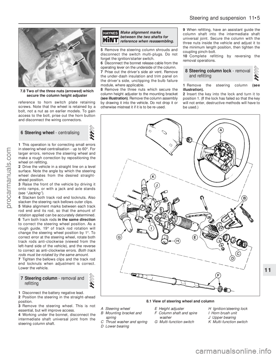
8Remove the three nuts which secure the
column height adjuster to the mounting bracket
(see illustration). Remove the column assembly
by drawing it into the vehicle. Do not drop it or
otherwise mistreat it if it is to be re-used.9When refitting, have an assistant guide the
column shaft into the intermediate shaft
universal joint. Secure the column with the
three nuts inside the vehicle and adjust it to
the minimum length position, then tighten the
coupling pinch-bolt.
10Complete refitting by reversing the
removal operations.
1Remove the steering column (see
illustration).
2Insert the key into the lock and turn it to
position 1. (If the lock has failed so that the key
will not enter, destructive methods will have to
be used.)
8Steering column lock - removal
and refitting
7Steering column - removal and
refitting
6Steering wheel - centralising
Steering and suspension 11•5
11
7.8 Two of the three nuts (arrowed) which
secure the column height adjuster
8.1 View of steering wheel and column
A Steering wheel
B Mounting bracket and
spring
C Thrust washer and spring
D Lower bearingE Height adjuster
F Column shaft and spire
washer
G Multi-function switchH Ignition/steering lock
I Horn brush unit
J Upper bearing
K Multi-function switch
Make alignment marks
between the two shafts for
reference when reassembling.
procarmanuals.com