1985 FORD GRANADA spare wheel
[x] Cancel search: spare wheelPage 60 of 255
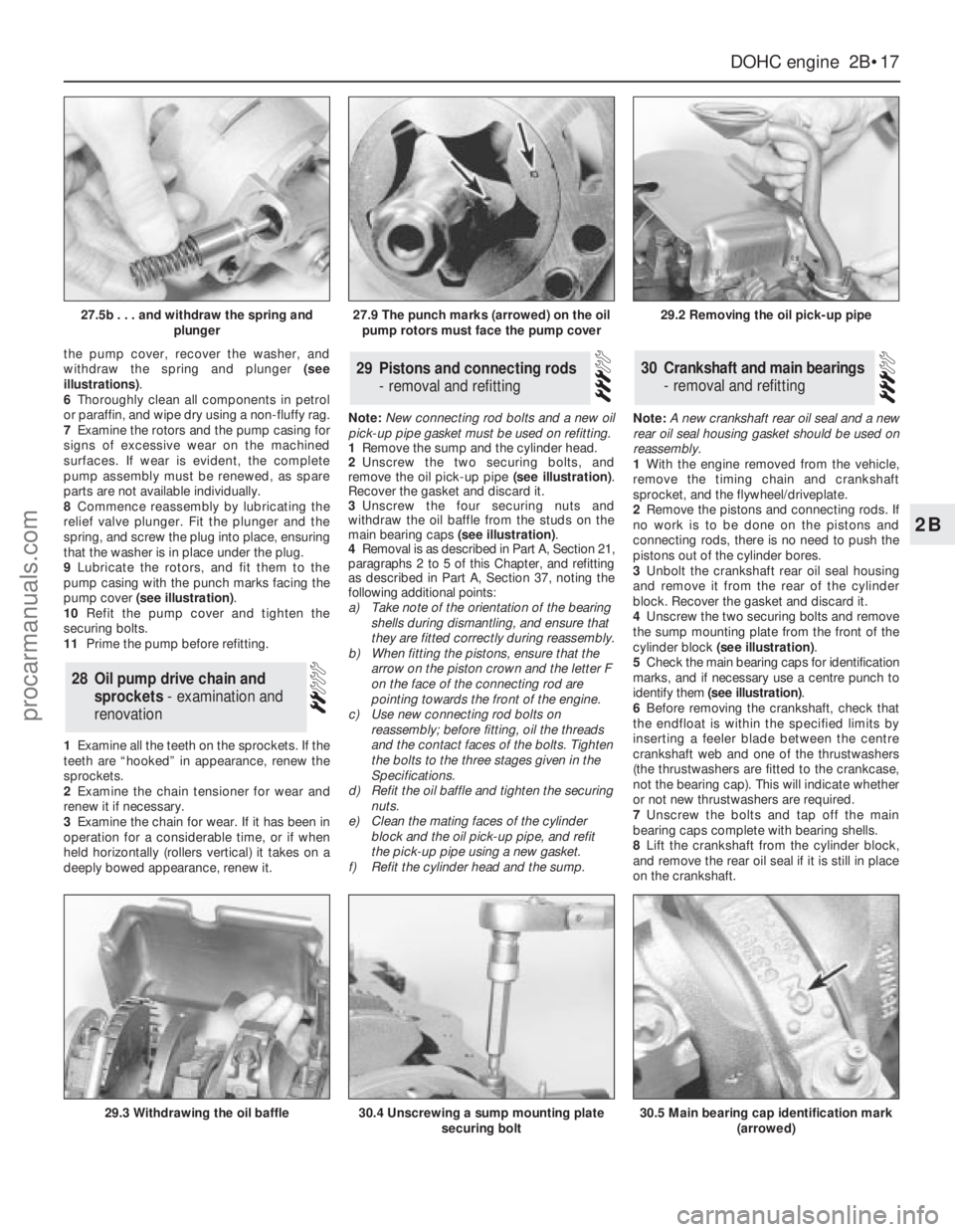
the pump cover, recover the washer, and
withdraw the spring and plunger (see
illustrations).
6Thoroughly clean all components in petrol
or paraffin, and wipe dry using a non-fluffy rag.
7Examine the rotors and the pump casing for
signs of excessive wear on the machined
surfaces. If wear is evident, the complete
pump assembly must be renewed, as spare
parts are not available individually.
8Commence reassembly by lubricating the
relief valve plunger. Fit the plunger and the
spring, and screw the plug into place, ensuring
that the washer is in place under the plug.
9Lubricate the rotors, and fit them to the
pump casing with the punch marks facing the
pump cover (see illustration).
10Refit the pump cover and tighten the
securing bolts.
11Prime the pump before refitting.
1Examine all the teeth on the sprockets. If the
teeth are “hooked” in appearance, renew the
sprockets.
2Examine the chain tensioner for wear and
renew it if necessary.
3Examine the chain for wear. If it has been in
operation for a considerable time, or if when
held horizontally (rollers vertical) it takes on a
deeply bowed appearance, renew it.Note: New connecting rod bolts and a new oil
pick-up pipe gasket must be used on refitting.
1Remove the sump and the cylinder head.
2Unscrew the two securing bolts, and
remove the oil pick-up pipe (see illustration).
Recover the gasket and discard it.
3Unscrew the four securing nuts and
withdraw the oil baffle from the studs on the
main bearing caps (see illustration).
4Removal is as described in Part A, Section 21,
paragraphs 2 to 5 of this Chapter, and refitting
as described in Part A, Section 37, noting the
following additional points:
a)Take note of the orientation of the bearing
shells during dismantling, and ensure that
they are fitted correctly during reassembly.
b)When fitting the pistons, ensure that the
arrow on the piston crown and the letter F
on the face of the connecting rod are
pointing towards the front of the engine.
c)Use new connecting rod bolts on
reassembly; before fitting, oil the threads
and the contact faces of the bolts. Tighten
the bolts to the three stages given in the
Specifications.
d)Refit the oil baffle and tighten the securing
nuts.
e)Clean the mating faces of the cylinder
block and the oil pick-up pipe, and refit
the pick-up pipe using a new gasket.
f)Refit the cylinder head and the sump.Note: A new crankshaft rear oil seal and a new
rear oil seal housing gasket should be used on
reassembly.
1With the engine removed from the vehicle,
remove the timing chain and crankshaft
sprocket, and the flywheel/driveplate.
2Remove the pistons and connecting rods. If
no work is to be done on the pistons and
connecting rods, there is no need to push the
pistons out of the cylinder bores.
3Unbolt the crankshaft rear oil seal housing
and remove it from the rear of the cylinder
block. Recover the gasket and discard it.
4Unscrew the two securing bolts and remove
the sump mounting plate from the front of the
cylinder block (see illustration).
5Check the main bearing caps for identification
marks, and if necessary use a centre punch to
identify them (see illustration).
6Before removing the crankshaft, check that
the endfloat is within the specified limits by
inserting a feeler blade between the centre
crankshaft web and one of the thrustwashers
(the thrustwashers are fitted to the crankcase,
not the bearing cap). This will indicate whether
or not new thrustwashers are required.
7Unscrew the bolts and tap off the main
bearing caps complete with bearing shells.
8Lift the crankshaft from the cylinder block,
and remove the rear oil seal if it is still in place
on the crankshaft.30Crankshaft and main bearings
- removal and refitting29Pistons and connecting rods
- removal and refitting
28Oil pump drive chain and
sprockets - examination and
renovation
DOHCengine 2B•17
2B
27.5b . . . and withdraw the spring and
plunger27.9 The punch marks (arrowed) on the oil
pump rotors must face the pump cover29.2 Removing the oil pick-up pipe
29.3 Withdrawing the oil baffle30.4 Unscrewing a sump mounting plate
securing bolt30.5 Main bearing cap identification mark
(arrowed)
procarmanuals.com
Page 99 of 255
25To remove the pump, first remove the fuel
tank.
26Unscrew the fuel pump/fuel level sender
unit by engaging two crossed screwdrivers in
the slots on either side of the unit mounting
flange. Recover the seal.
27Refitting is a reversal of removal. It is
necessary to fit a new seal.
1Run the fuel level as low as possible before
removing the tank.
2Disconnect the battery negative lead.
3Remove the fuel filler cap. Siphon or pump
the remaining fuel out of the tank. Store the
fuel in a suitable sealed container.
4Remove the two screws on either side of the
filler neck.
5Raise and support the rear of the vehicle.
6Remove the shield from the right-hand rear
inner wheel arch. Also remove the rear bumper
undershield. which is secured by six screws.
7Disconnect the fuel supply and return lines
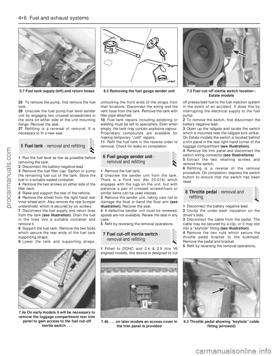
from the tank (see illustration). Drain the fuel
in the lines into a suitable container and
remove it.
8Support the fuel tank. Remove the two bolts
which secure the rear ends of the fuel tank
supporting straps.
9Lower the tank and supporting straps,unhooking the front ends of the straps from
their locations. Disconnect the wiring and the
vent hose from the tank. Remove the tank with
filler pipe attached.
10Fuel tank repairs including soldering or
welding must be left to specialists. Even when
empty, the tank may contain explosive vapour.
Proprietary compounds are available for
making temporary “cold” repairs.
11Refit the fuel tank in the reverse order to
removal. Check for leaks on completion.
1Remove the fuel tank.
2Unscrew the sender unit from the tank.
There is a Ford tool (No 23-014) which
engages with the lugs on the unit, but with
patience a pair of crossed screwdrivers or
similar items can be used instead.
3Remove the sender unit, taking care not to
damage the float or bend the float arm(see
illustration).Recover the seal.
4A defective sender unit must be renewed;
spares are not available. Renew the seal in any
case.
5Refit by reversing the removal operations.
1Fitted to DOHC and 2.4 & 2.9 litre V6
engined models, this device is designed to cutoff pressurised fuel to the fuel-injection system
in the event of an accident. It does this by
interrupting the electrical supply to the fuel
pump.
2To remove the switch, first disconnect the
battery negative lead.
3Open up the tailgate and locate the switch
which is mounted near the tailgate lock striker.
On Estate models the switch is located behind
a trim panel in the rear right-hand corner of the
luggage compartment (see illustration).
4Remove the trim panel and disconnect the
switch wiring connector (see illustrations).
5Extract the two retaining screws and
remove the switch.
6Refitting is a reverse of the removal
procedure. On completion, depress the switch
button to ensure that the switch has been
reset.
1Disconnect the battery negative lead.
2Unclip the under-dash insulation on the
driver’s side.
3Disconnect the cable from the pedal. The
cable may be secured by a clip, or it may slot
into a “keyhole” fitting (see illustration).
4Remove the two nuts which secure the
throttle pedal bracket to the bulkhead.
Remove the pedal and bracket.
5Refit by reversing the removal operations.
8Throttle pedal - removal and
refitting
7Fuel cut-off inertia switch -
removal and refitting
6Fuel gauge sender unit -
removal and refitting
5Fuel tank - removal and refitting
4•6Fuel and exhaust systems
5.7 Fuel tank supply (left) and return hoses
7.4a On early models it will be necessary to
remove the luggage compartment rear trim
panel to gain access to the fuel cut-off
inertia switch . . .
7.4b . . . on later models an access cover in
the trim panel is provided8.3 Throttle pedal showing “keyhole” cable
fitting (arrowed)
6.3 Removing the fuel gauge sender unit7.3 Fuel cut-off inertia switch location -
Estate models
procarmanuals.com
Page 141 of 255
3Press the multi-plug locking lever,
disconnect the multi-plug and unhook it from
the module. Remove the module.
4Refit by reversing the removal operations.
Make sure that the multi-plug is properly
engaged before refitting the module.
Front
1Ensure that the handbrake is applied. Raise
and support the front of the vehicle.
2From under the bonnet disconnect the
wheel sensor wiring multi-plug. Unclip the
wiring, working towards the sensor.
3Remove the securing bolt and withdraw the
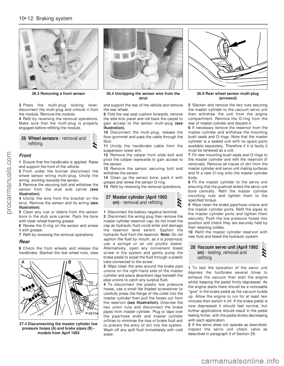
sensor from the stub axle carrier (see
illustration).
4Unclip the wire from the bracket on the
strut. Remove the sensor and its wiring (see
illustration).
5Clean any rust or debris from the sensor
bore in the stub axle carrier. Pack the bore
with clean wheel bearing grease.
6Renew the O-ring on the sensor and smear
it with grease.
7Refit by reversing the removal operations.
Rear
8Chock the front wheels and release the
handbrake. Slacken the rear wheel nuts, raiseand support the rear of the vehicle and remove
the rear wheel.
9Fold the rear seat cushion forwards, remove
the side kick panel and roll back the carpet to
gain access to the sensor multi-plug (see
illustration).
10Disconnect the multi-plug, release the
floor grommet and pass the cable through the
floor.
11Unclip the handbrake cable from the
suspension lower arm.
12Remove the caliper front slide bolt and
pivot the caliper rearwards to gain access to
the sensor.
13Remove the sensor securing bolt and
withdraw the sensor.
14Clean up the sensor bore, pack it with
grease and renew the sensor O-ring.
15Refit by reversing the removal operations.
1Disconnect the battery negative terminal.
2Disconnect the wiring plug then remove the
master cylinder reservoir cap; do not invert the
cap as hydraulic fluid could enter and damage
the reservoir level switch. Syphon the
hydraulic fluid from the reservoir. Note: Do not
syphon the fluid by mouth, as it is poisonous;
use a syringe or an old poultry baster.
Alternatively, open any convenient bleed
screw in the system and gently pump the
brake pedal to expel the fluid through a plastic
tube connected to the screw.
3Wipe clean the area around the brake pipe
unions on the right-hand side of the master
cylinder and place absorbent rags beneath the
pipe unions to catch any surplus fluid.
4To disconnect the plastic low pressure
hoses, use a small flat bladed screwdriver to
carefully press the flange of the collet into the
master cylinder then pull the hoses out from
the reservoir(see illustration).Unscrew the
two union nuts and disconnect the brake
pipes from master cylinder. Plug or tape over
the pipe/hose ends and master cylinder
orifices to minimise the loss of brake fluid and
to prevent the entry of dirt into the system.
Wash off any spilt fluid immediately with cold
water.5Slacken and remove the two nuts securing
the master cylinder to the vacuum servo unit
then withdraw the unit from the engine
compartment. Remove the O-ring from the
rear of master cylinder and discard it.
6If necessary remove the reservoir from the
master cylinder and withdraw the mounting
bush seals and O-rings. Note that the master
cylinder is a sealed unit with no spare parts
available separately. Therefore if it is faulty it
must be renewed as a unit.
7Fit new mounting bush seals and O-rings to
the master cylinder and refit the reservoir (if
removed). Remove all traces of dirt from the
master cylinder and servo unit mating surfaces
and fit a new O-ring onto the master cylinder
body.
8Fit the master cylinder to the servo unit
ensuring that the pushrod enters the servo unit
bore centrally. Refit the master cylinder
mounting nuts and tighten them to the
specified torque.
9Wipe clean the brake pipe/hose unions and
the master cylinder ports. Refit the pipes to
the master cylinder ports and tighten them
securely. Push the low pressure hoses into
position and check they are securely held by
their retaining collets.
10Refill the master cylinder reservoir with
new fluid and bleed the hydraulic system
1To test the operation of the servo unit
depress the footbrake several times to
exhaust the vacuum then start the engine
whilst keeping the pedal firmly depressed. As
the engine starts there should be a noticeable
“give” in the brake pedal as the vacuum builds
up. Allow the engine to run for at least two
minutes then switch it off. If the brake pedal is
now depressed it should feel normal, but
further applications should result in the pedal
feeling firmer, with the pedal stroke decreasing
with each application.
2If the servo does not operate as described,
inspect the servo unit check valve as
describedin paragraph 3 of Section 29.28Vacuum servo unit (April 1992
on) - testing, removal and
refitting
27Master cylinder (April 1992
on) - removal and refitting
26Wheel sensors - removal and
refitting
10•12Braking system
26.3 Removing a front sensor
27.4 Disconnecting the master cylinder low
pressure hoses (A) and brake pipes (B) -
models from April 1992
26.4 Unclipping the sensor wire from the
strut26.9 Rear wheel sensor multi-plug
(arrowed)
procarmanuals.com
Page 150 of 255
6When refitting, screw the track rod end onto
the track rod as far as the locknut, then back it
off half a turn.
7Insert the ball-pin into the steering arm.
Tighten the balljoint nut to the specified torque
and secure with a new split pin. Nip up the
track rod end locknut, but do not tighten it fully
yet.
8Refit the roadwheel, lower the vehicle and
tighten the wheel nuts to the specified torque.
9Check the toe setting as described in the
following Section. (This may not be strictly
necessary if the same track rod end has been
refitted, but is certainly advisable if any
components have been renewed.)
10Tighten the track rod end locknut when
toe is correct.
1Front wheel alignment is defined by camber,
castor, steering axis inclination and toe
setting. The first three factors are determined
in production; only toe can be adjusted in
service. Incorrect toe will cause rapid tyre
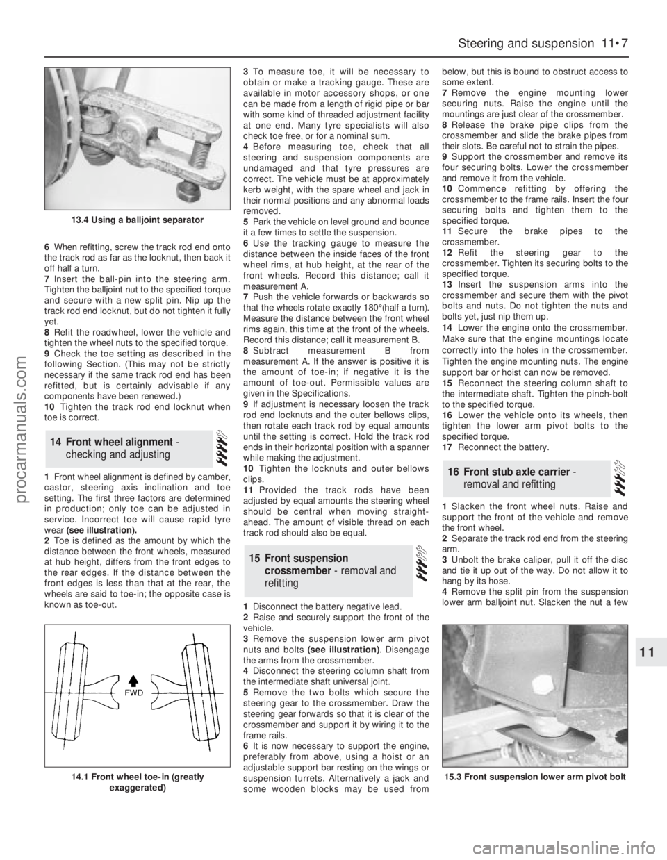
wear (see illustration).
2Toe is defined as the amount by which the
distance between the front wheels, measured
at hub height, differs from the front edges to
the rear edges. If the distance between the
front edges is less than that at the rear, the
wheels are said to toe-in; the opposite case is
known as toe-out.3To measure toe, it will be necessary to
obtain or make a tracking gauge. These are
available in motor accessory shops, or one
can be made from a length of rigid pipe or bar
with some kind of threaded adjustment facility
at one end. Many tyre specialists will also
check toe free, or for a nominal sum.
4Before measuring toe, check that all
steering and suspension components are
undamaged and that tyre pressures are
correct. The vehicle must be at approximately
kerb weight, with the spare wheel and jack in
their normal positions and any abnormal loads
removed.
5Park the vehicle on level ground and bounce
it a few times to settle the suspension.
6Use the tracking gauge to measure the
distance between the inside faces of the front
wheel rims, at hub height, at the rear of the
front wheels. Record this distance; call it
measurement A.
7Push the vehicle forwards or backwards so
that the wheels rotate exactly 180°(half a turn).
Measure the distance between the front wheel
rims again, this time at the front of the wheels.
Record this distance; call it measurement B.
8Subtract measurement B from
measurement A. If the answer is positive it is
the amount of toe-in; if negative it is the
amount of toe-out. Permissible values are
given in the Specifications.
9If adjustment is necessary loosen the track
rod end locknuts and the outer bellows clips,
then rotate each track rod by equal amounts
until the setting is correct. Hold the track rod
ends in their horizontal position with a spanner
while making the adjustment.
10Tighten the locknuts and outer bellows
clips.
11Provided the track rods have been
adjusted by equal amounts the steering wheel
should be central when moving straight-
ahead. The amount of visible thread on each
track rod should also be equal.
1Disconnect the battery negative lead.
2Raise and securely support the front of the
vehicle.
3Remove the suspension lower arm pivot
nuts and bolts (see illustration). Disengage
the arms from the crossmember.
4Disconnect the steering column shaft from
the intermediate shaft universal joint.
5Remove the two bolts which secure the
steering gear to the crossmember. Draw the
steering gear forwards so that it is clear of the
crossmember and support it by wiring it to the
frame rails.
6It is now necessary to support the engine,
preferably from above, using a hoist or an
adjustable support bar resting on the wings or
suspension turrets. Alternatively a jack and
some wooden blocks may be used frombelow, but this is bound to obstruct access to
some extent.
7Remove the engine mounting lower
securing nuts. Raise the engine until the
mountings are just clear of the crossmember.
8Release the brake pipe clips from the
crossmember and slide the brake pipes from
their slots. Be careful not to strain the pipes.
9Support the crossmember and remove its
four securing bolts. Lower the crossmember
and remove it from the vehicle.
10Commence refitting by offering the
crossmember to the frame rails. Insert the four
securing bolts and tighten them to the
specified torque.
11Secure the brake pipes to the
crossmember.
12Refit the steering gear to the
crossmember. Tighten its securing bolts to the
specified torque.
13Insert the suspension arms into the
crossmember and secure them with the pivot
bolts and nuts. Do not tighten the nuts and
bolts yet, just nip them up.
14Lower the engine onto the crossmember.
Make sure that the engine mountings locate
correctly into the holes in the crossmember.
Tighten the engine mounting nuts. The engine
support bar or hoist can now be removed.
15Reconnect the steering column shaft to
the intermediate shaft. Tighten the pinch-bolt
to the specified torque.
16Lower the vehicle onto its wheels, then
tighten the lower arm pivot bolts to the
specified torque.
17Reconnect the battery.
1Slacken the front wheel nuts. Raise and
support the front of the vehicle and remove
the front wheel.
2Separate the track rod end from the steering
arm.
3Unbolt the brake caliper, pull it off the disc
and tie it up out of the way. Do not allow it to
hang by its hose.
4Remove the split pin from the suspension
lower arm balljoint nut. Slacken the nut a few
16Front stub axle carrier -
removal and refitting
15Front suspension
crossmember - removal and
refitting
14Front wheel alignment -
checking and adjusting
Steering and suspension 11•7
11
13.4 Using a balljoint separator
14.1 Front wheel toe-in (greatly
exaggerated)15.3 Front suspension lower arm pivot bolt
procarmanuals.com
Page 254 of 255
Q
Quarter window moulding - 12•10
R
Radiator - 3•3, 12•9
Radio fader light - 13•8
Radio or radio/cassette player - 13•20, 13•21
Rear light cluster - 13•5, 13•6
Recline motor - 13•15
Regulator mechanism - 12•9
Relays - 13•13
Respraying - 12•3
Reversing light switch - 7B•3, 13•12, 13•13
Ride height control - 11•12, 11•13
Road test - 1•16
Rocker shaft - 2C•12
Rotor arm - 5•5
Routine maintenance and servicing- 1•1et
seq
Rust holes or gashes in bodywork - 12•2
S
Safety first! - 0•5
Scalding - 0•5
Scratches in bodywork - 12•2
Screw threads and fastenings - REF•4
Seals and hoses - 1•19
Seat air cushion - 12•17
Seat belts - 0•12, 1•10, 12•17, 12•18
Seats - 0•12, 12•17, 12•18, 13•10, 13•13,
13•15
Selector rod - 7B•4
Servo - 10•12, 10•13, 13•20
Shock absorbers - 0•12, 0•13, 11•12
Short-circuit - 13•4
Side mouldings - 12•10
Sidelight - 13•4
Sliding roof - 12•5, 13•12, 13•16
Spare parts - 0•8
Spark plugs - 1•12, 5•5
Speakers - 13•21, 13•22
Speed control system components - 13•19,
13•20
Speedometer sender unit - 13•16
Spoiler - 12•11
Springs - 0•13, 11•11
Starter inhibitor/reversing light switch -
7B•3, 13•13
Starter motor - 5•4, 5•5
Starter motor noisy or excessively-rough in
engagement - REF•6
Starter motor turns engine slowly - REF•6
Steering and suspension - 0•12, 0•13, 1•15,
1•16, 11•1et seq,REF•10
Steering column- 0•11, 11•5
Steering gear - 11•3
Steering intermediate shaft and flexible
coupling - 11•6Steering play - REF•10
Steering rack bellows - 11•4
Steering stiff - REF•10
Steering wheel - 0•11, 11•4, 11•5
Steering wheel and column -
Stop-light switch - 13•12
Strut - 11•9, 11•10
Stub axle carrier - 11•7
Sump - 2A•9, 2A•16, 2B•15, 2C•9, 2C•19
Switch illumination lights - 13•8
Switches - 13•9, 13•11, 13•12, 13•13,
13•18, 13•19
T
Tailgate - 12•4, 12•7, 13•12, 13•18
Tailgate wash/wipe inoperative, or
unsatisfactory in operation - REF•11
Tailgate window mouldings - 12•10
Tappets - 2C•13
Temperature gauge gives false reading -
REF•11
Temperature gauge sender - 3•7
Thermostat - 3•3
Throttle body - 4•15
Throttle cable - 4•7
Throttle kicker - 4•13
Throttle pedal - 4•6
Throttle position sensor - 4•15
Timing belt - 2A•8, 2A•14, 2A•18
Timing chain - 2B•8, 2B•10, 2C•9, 2C•17
Tools and working facilities- REF•1et seq
Towing - 0•7
Track rod end - 11•6
Transmission fluid brown, or has burned
smell - REF•9
Transmission slips, shifts roughly, is noisy,
or has no drive in forward or reverse
gears - REF•9
Transmission will not downshift (kickdown)
with accelerator pedal fully depressed -
REF•9
Tyre wear - REF•10
Tyres - 0•14, 1•7
U
Ultrasonic sensor - 13•23
Underbody inspection - 1•15
Unleaded fuel - 4•23
V
Vacuum dump valve/switch - 13•19
Vacuum hoses - 2C•7
Vacuum line modification - 7B•4
Vacuum pull-down adjustment - 4•13
Vacuum pump - 13•20
Vacuum servo - 10•12, 10•13, 13•20
Valve block and pump assembly - 10•13
Valve clearances - 1•13, 2A•20, 2C•21Valve grinding - 2A•14
Vane airflow meter(s) - 4•16
Vanity mirror light - 13•7
Vapour separator - 4•7
Vehicle identification - 0•9, 0•12
Vehicle pulls to one side - REF•9, REF•10
Vehicle speed sensor - 5•12
Vibration damper (MT75type gearbox) - 8•4
Viscous-coupled fan - 3•5
W
Wandering or general instability - REF•10
Warning light bulbs - 13•18
Wash/wipe inoperative, or unsatisfactory in
operation - REF•11
Wash/wipe switch - 13•12
Washer fluid - 1•7, 13•19
Washer jets inoperative - REF•11
Washer pump fails to operate - REF•11
Washer pump runs for some time before
fluid is emitted from jets - REF•11
Water pump - 3•5
Water pump/alternator drivebelt - 3•7
Weatherstrip - 12•7
Weber 2V carburettor - 4•9, 4•10
Weber 2V TLD carburettor - 4•11, 4•12,
4•13
Wheel alignment - 11•7
Wheel bearings - 0•13, 11•8, 11•11
Wheel changing - 0•7
Wheel sensors - 10•12
Wheel stud - 11•11
Wheel wobble and vibration - REF•10
Wheels - 0•14, 1•10
Wheels locking under normal braking -
REF•10
Window frame mouldings - 12•10
Window glass - 12•8
Window glass fails to move - REF•11
Window glass slow to move - REF•11
Window glass will only move in one
direction - REF•11
Window operating motor - 13•15
Window operating switch - 13•12
Windscreen - 0•11, 12•9
Windscreen mouldings - 12•10
Windscreen, rear window and headlight
washer components - 13•17
Wiper arms and blades - 13•16
Wiper blades - 1•9
Wiper blades fail to clean the glass
effectively - REF•11
Wiper blades sweep over too large or too
small an area of the glass - REF•11
Wiper motor - 13•17
Wipers fail to operate, or operate very
slowly - REF•11
Wiring diagrams- WD•0 et seq
Working facilities - REF•3
IND•3Index
procarmanuals.com