1985 FORD GRANADA tailgate
[x] Cancel search: tailgatePage 13 of 255
1Work around the vehicle, and lubricate the
hinges and locks with a light machine oil.
2Lightly lubricate the bonnet release
mechanism and exposed sections of inner
cable with a smear of grease.
3Check the security and operation of all
hinges, latches and locks, adjusting them
where required. Where applicable, check the
operation of the central locking system.
4Check the condition and operation of the
tailgate struts, renewing them if either is
leaking or is no longer able to support the
tailgate securely when raised.
SOHC and V6 engines
1The correct functioning of the spark plugs is
vital for the correct running and efficiency of
the engine. It is essential that the plugs fitted
are appropriate for the engine.
2Make sure that the ignition is switched off
before inspecting the HT leads to see if they
carry their cylinder numbers - if not, number
each lead using sticky tape or paint.
3Pull the HT lead connectors off the plugs.
Pull on the connectors, not on the leads.
4Blow away any dirt from around the spark
plug recesses in the cylinder head(s).
5Unscrew and remove the plugs, using a
proprietary plug spanner or a spark plug
socket, extension and ratchet.
6The condition of the plugs will tell much
about the overall condition of the engine. If the
insulator nose of the spark plug is clean and
white, with no deposits, this is indicative of a
weak mixture or too hot a plug (a hot plug
transfers heat away from the electrode slowly,
a cold plug transfers heat away quickly).
7If the tip and insulator nose are covered with
hard black-looking deposits, then this is
indicative that the mixture is too rich. Should
the plug be black and oily, then it is likely that
the engine is fairly worn, as well as the mixture
being too rich.
8If the insulator nose is covered with light tan
to greyish-brown deposits, then the mixture is
correct, and it is likely that the engine is in
good condition.
9Apply a smear of anti-seize compound to
the threads of the new plugs. Make sure that
theinsulators are clean and that the screwed
HT lead adapters are tight. Pay particular
attention to the plug seating surfaces on OHC
engines, since these plugs have no sealing
washers (“taper seat” type) and any dirt will
cause a bad seal.
10Screw each plug into its hole by hand. If a
plug is reluctant to go in, do not force it with a
spanner, but unscrew it and try again. If the
plug is cross-threaded, it is the cylinder head
which will be damaged.11Final tightening of the spark plugs should
ideally be carried out using a torque wrench.
The tightening torques are given in the
Specifications. If a torque wrench is not
available, tighten the plugs beyond the point
where they contact the head as follows:
OHC (taper seat plugs) - One-sixteenth of a
turn maximum
V6 (plugs with washers) - One-quarter of a
turn maximum
12If the taper seat type of plug is
overtightened, the sealing faces will bite
together and removal will be very difficult.
13Refit the HT leads to the plugs, paying
attention to the cylinder numbers. Push each
connector firmly onto its plug.
14Run the engine to verify that the HT leads
have been refitted correctly.
DOHC engines
15Proceed as described above whilst noting
the following points.
a)Remove the air cleaner as described in
Chapter 4.
b)The minimal length of number 3 HT lead
makes removal from the spark plug
difficult. It is advisable to remove this lead
from the distributor prior to removing it
from the spark plug.
c)The spark plugs are deeply recessed in
the cylinder head and it will be necessary
to use a spark plug socket with a long
extension bar. If possible, use a spark plug
socket with a rubber grip inside as this will
hold onto the spark plug once loosened
and will enable the spark plugs to be
withdrawn and refitted more easily.
SOHC and all V6 engines
1All of these engines have one or two
drivebelts which drive the water pump and
alternator from the crankshaft pulley. When
power steering is fitted, the same belts drive
the steering pump. The air conditioning
compressor, when fitted, is driven
independently.
2Periodically inspect the drivebelt(s) for
fraying, cracks, glazing or other damage. Turn
the engine so that the full length of the belt(s)
can be viewed. Renew belts which are in poor
condition. When twin drivebelts are fitted, both
must be renewed together, even if only one is
damaged.
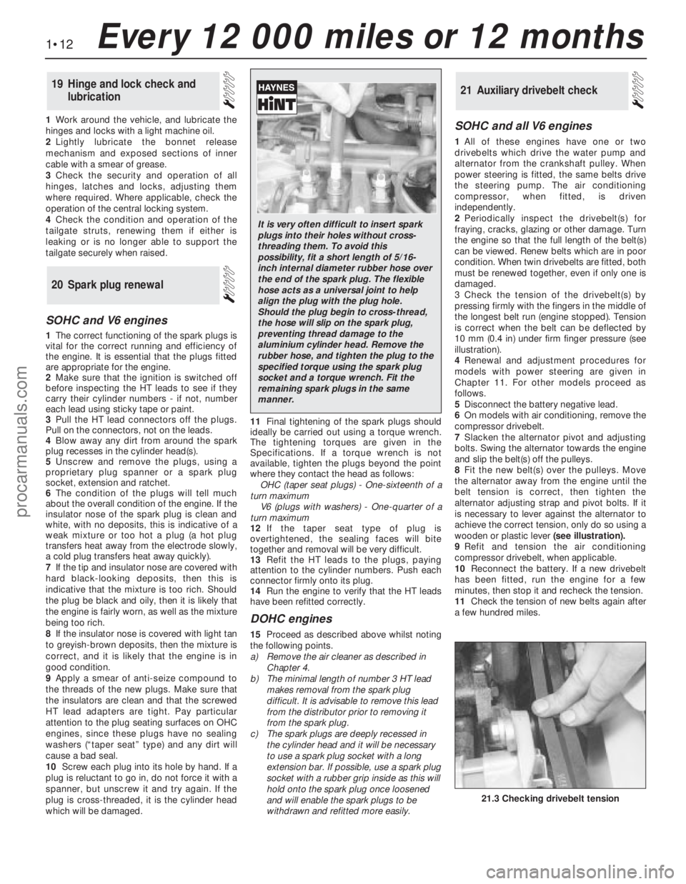
3Check the tension of the drivebelt(s) by
pressing firmly with the fingers in the middle of
the longest belt run (engine stopped). Tension
is correct when the belt can be deflected by
10 mm (0.4 in) under firm finger pressure (see
illustration).
4Renewal and adjustment procedures for
models with power steering are given in
Chapter 11. For other models proceed as
follows.
5Disconnect the battery negative lead.
6On models with air conditioning, remove the
compressor drivebelt.
7Slacken the alternator pivot and adjusting
bolts. Swing the alternator towards the engine
and slip the belt(s) off the pulleys.
8Fit the new belt(s) over the pulleys. Move
the alternator away from the engine until the
belt tension is correct, then tighten the
alternator adjusting strap and pivot bolts. If it
is necessary to lever against the alternator to
achieve the correct tension, only do so using a
wooden or plastic lever(seeillustration).
9Refit and tension the air conditioning
compressor drivebelt, when applicable.
10Reconnect the battery. If a new drivebelt
has been fitted, run the engine for a few
minutes, then stop it and recheck the tension.
11Check the tension of new belts again after
a few hundred miles.
21Auxiliary drivebelt check
20Spark plug renewal
19Hinge and lock check and
lubrication
1•12Every 12 000 miles or 12 months
21.3 Checking drivebelt tension
It is very often difficult to insert spark
plugs into their holes without cross-
threading them. To avoid this
possibility, fit a short length of 5/16-
inch internal diameter rubber hose over
the end of the spark plug. The flexible
hose acts as a universal joint to help
align the plug with the plug hole.
Should the plug begin to cross-thread,
the hose will slip on the spark plug,
preventing thread damage to the
aluminium cylinder head. Remove the
rubber hose, and tighten the plug to the
specified torque using the spark plug
socket and a torque wrench. Fit the
remaining spark plugs in the same
manner.
procarmanuals.com
Page 99 of 255
25To remove the pump, first remove the fuel
tank.
26Unscrew the fuel pump/fuel level sender
unit by engaging two crossed screwdrivers in
the slots on either side of the unit mounting
flange. Recover the seal.
27Refitting is a reversal of removal. It is
necessary to fit a new seal.
1Run the fuel level as low as possible before
removing the tank.
2Disconnect the battery negative lead.
3Remove the fuel filler cap. Siphon or pump
the remaining fuel out of the tank. Store the
fuel in a suitable sealed container.
4Remove the two screws on either side of the
filler neck.
5Raise and support the rear of the vehicle.
6Remove the shield from the right-hand rear
inner wheel arch. Also remove the rear bumper
undershield. which is secured by six screws.
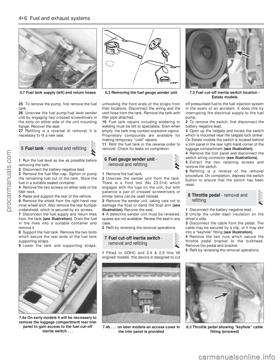
7Disconnect the fuel supply and return lines
from the tank (see illustration). Drain the fuel
in the lines into a suitable container and
remove it.
8Support the fuel tank. Remove the two bolts
which secure the rear ends of the fuel tank
supporting straps.
9Lower the tank and supporting straps,unhooking the front ends of the straps from
their locations. Disconnect the wiring and the
vent hose from the tank. Remove the tank with
filler pipe attached.
10Fuel tank repairs including soldering or
welding must be left to specialists. Even when
empty, the tank may contain explosive vapour.
Proprietary compounds are available for
making temporary “cold” repairs.
11Refit the fuel tank in the reverse order to
removal. Check for leaks on completion.
1Remove the fuel tank.
2Unscrew the sender unit from the tank.
There is a Ford tool (No 23-014) which
engages with the lugs on the unit, but with
patience a pair of crossed screwdrivers or
similar items can be used instead.
3Remove the sender unit, taking care not to
damage the float or bend the float arm(see
illustration).Recover the seal.
4A defective sender unit must be renewed;
spares are not available. Renew the seal in any
case.
5Refit by reversing the removal operations.
1Fitted to DOHC and 2.4 & 2.9 litre V6
engined models, this device is designed to cutoff pressurised fuel to the fuel-injection system
in the event of an accident. It does this by
interrupting the electrical supply to the fuel
pump.
2To remove the switch, first disconnect the
battery negative lead.
3Open up the tailgate and locate the switch
which is mounted near the tailgate lock striker.
On Estate models the switch is located behind
a trim panel in the rear right-hand corner of the
luggage compartment (see illustration).
4Remove the trim panel and disconnect the
switch wiring connector (see illustrations).
5Extract the two retaining screws and
remove the switch.
6Refitting is a reverse of the removal
procedure. On completion, depress the switch
button to ensure that the switch has been
reset.
1Disconnect the battery negative lead.
2Unclip the under-dash insulation on the
driver’s side.
3Disconnect the cable from the pedal. The
cable may be secured by a clip, or it may slot
into a “keyhole” fitting (see illustration).
4Remove the two nuts which secure the
throttle pedal bracket to the bulkhead.
Remove the pedal and bracket.
5Refit by reversing the removal operations.
8Throttle pedal - removal and
refitting
7Fuel cut-off inertia switch -
removal and refitting
6Fuel gauge sender unit -
removal and refitting
5Fuel tank - removal and refitting
4•6Fuel and exhaust systems
5.7 Fuel tank supply (left) and return hoses
7.4a On early models it will be necessary to
remove the luggage compartment rear trim
panel to gain access to the fuel cut-off
inertia switch . . .
7.4b . . . on later models an access cover in
the trim panel is provided8.3 Throttle pedal showing “keyhole” cable
fitting (arrowed)
6.3 Removing the fuel gauge sender unit7.3 Fuel cut-off inertia switch location -
Estate models
procarmanuals.com
Page 158 of 255
Chapter 12
Bodywork and fittings
Bonnet - removal and refitting . . . . . . . . . . . . . . . . . . . . . . . . . . . . . .6
Bonnet insulation panel - removal and refitting . . . . . . . . . . . . . . . .26
Bonnet release cable - removal and refitting . . . . . . . . . . . . . . . . . .11
Boot lid lock barrel - removal and refitting . . . . . . . . . . . . . . . . . . . .18
Boot lid - removal, refitting and adjustment . . . . . . . . . . . . . . . . . . . .9
Bumper mouldings - removal and refitting . . . . . . . . . . . . . . . . . . . .36
Bumpers - removal and refitting . . . . . . . . . . . . . . . . . . . . . . . . . . . .35
Centre console - removal and refitting . . . . . . . . . . . . . . . . . . . . . . .42
Door - removal and refitting . . . . . . . . . . . . . . . . . . . . . . . . . . . . . . . .7
Door exterior handle - removal and refitting . . . . . . . . . . . . . . . . . .13
Door interior trim panel - removal and refitting . . . . . . . . . . . . . . . .22
Door latch assembly - removal and refitting . . . . . . . . . . . . . . . . . .15
Door lock barrel - removal and refitting . . . . . . . . . . . . . . . . . . . . . .14
Door striker plate - adjustment . . . . . . . . . . . . . . . . . . . . . . . . . . . . .12
Door weatherstrip - removal and refitting . . . . . . . . . . . . . . . . . . . .16
Door window frame mouldings - removal and refitting . . . . . . . . . .31
Door window glass - removal and refitting . . . . . . . . . . . . . . . . . . . .23
Door window regulator mechanism - removal and refitting . . . . . . .24
Exterior mirror - removal and refitting . . . . . . . . . . . . . . . . . . . . . . .39
Facia panels and trim - removal and refitting . . . . . . . . . . . . . . . . . .41
Front bumper - height adjustment . . . . . . . . . . . . . . . . . . . . . . . . . .34
Front seat - removal and refitting . . . . . . . . . . . . . . . . . . . . . . . . . . .44
Front seat air cushion - removal and refitting . . . . . . . . . . . . . . . . .45
Front seat belts - removal and refitting . . . . . . . . . . . . . . . . . . . . . .47
Front spoiler - removal and refitting . . . . . . . . . . . . . . . . . . . . . . . . .37Fuel filler lock barrel - removal and refitting . . . . . . . . . . . . . . . . . . .21
General information . . . . . . . . . . . . . . . . . . . . . . . . . . . . . . . . . . . . . .1
Headlining - removal and refitting . . . . . . . . . . . . . . . . . . . . . . . . . .38
Interior mirror - removal and refitting . . . . . . . . . . . . . . . . . . . . . . . .40
Maintenance - bodywork and underframe . . . . . . . . . . . . . . . . . . . . .2
Maintenance - upholstery and carpets . . . . . . . . . . . . . . . . . . . . . . . .3
Major body damage - repair . . . . . . . . . . . . . . . . . . . . . . . . . . . . . . . .5
Minor body damage - repair . . . . . . . . . . . . . . . . . . . . . . . . . . . . . . . .4
Motifs and emblems - removal and refitting . . . . . . . . . . . . . . . . . .33
Overhead console - removal and refitting . . . . . . . . . . . . . . . . . . . .43
Radiator grille - removal and refitting . . . . . . . . . . . . . . . . . . . . . . . .27
Rear parcel shelf - removal and refitting . . . . . . . . . . . . . . . . . . . . .50
Rear quarter window moulding - removal and refitting . . . . . . . . . .32
Rear seat belts - removal and refitting . . . . . . . . . . . . . . . . . . . . . . .48
Rear seat components - removal and refitting . . . . . . . . . . . . . . . . .49
Seat belts - care and maintenance . . . . . . . . . . . . . . . . . . . . . . . . .46
Side mouldings - removal and refitting . . . . . . . . . . . . . . . . . . . . . .28
Sliding roof - removal and refitting . . . . . . . . . . . . . . . . . . . . . . . . . .10
Tailgate - removal and refitting . . . . . . . . . . . . . . . . . . . . . . . . . . . . . .8
Tailgate latch assembly - removal and refitting . . . . . . . . . . . . . . . .19
Tailgate lock barrel - removal and refitting . . . . . . . . . . . . . . . . . . . .17
Tailgate strut - removal and refitting . . . . . . . . . . . . . . . . . . . . . . . .20
Tailgate window mouldings - removal and refitting . . . . . . . . . . . . .30
Windscreen and fixed glass - removal and refitting . . . . . . . . . . . . .25
Windscreen mouldings - removal and refitting . . . . . . . . . . . . . . . .29
Torque wrench settingsNm lbf ft
Front seat belt buckle to seat frame . . . . . . . . . . . . . . . . . . . . . . . . . . . . 51 to 64 38 to 47
Seat belt retractor bolts (front and rear) . . . . . . . . . . . . . . . . . . . . . . . . . 25 to 45 18 to 33
Other seat belt anchorages . . . . . . . . . . . . . . . . . . . . . . . . . . . . . . . . . . 25 to 45 18 to 33
Rear seat back hinge to body . . . . . . . . . . . . . . . . . . . . . . . . . . . . . . . . . 21 to 25 16 to 18
Rear seat back latch striker . . . . . . . . . . . . . . . . . . . . . . . . . . . . . . . . . . 40 to 60 30 to 44
Front seat retaining bolts . . . . . . . . . . . . . . . . . . . . . . . . . . . . . . . . . . . . 25 to 32 18 to 24
Front seat frame-to-slide bolts . . . . . . . . . . . . . . . . . . . . . . . . . . . . . . . . 25 to 32 18 to 24
Rear bumper mountings . . . . . . . . . . . . . . . . . . . . . . . . . . . . . . . . . . . . . 21 16
Front bumper adjuster lockbolt . . . . . . . . . . . . . . . . . . . . . . . . . . . . . . . 21 16
12•1
Easy,suitable for
novice with little
experienceFairly easy,suitable
for beginner with
some experienceFairly difficult,
suitable for competent
DIY mechanicDifficult,suitable for
experienced DIY
mechanicVery difficult,
suitable for expert
DIY or professional
Degrees of difficulty
Specifications Contents
12
The bodyshell and floorpan are of pressed
steel, and form an integral part of the vehicle’s
structure. Various reinforcing and mounting
components beneath the floorpan are made of
HSLA (High Strength Low Alloy) and REPHOS
(rephosphorised) steels, which have superiorstrength-to-weight characteristics when
compared with conventional steels.
Extensive use is made of plastic for
peripheral components such as the radiator
grille, bumpers and wheel trims, and for much
of the interior trim.
Interior fittings are to the high standard
expected in a vehicle of this class, with even
the basic level models well equipped. A wide
range of options is available, including air
conditioning and leather upholstery.The general condition of a vehicle’s
bodywork is the one thing that significantly
affects its value. Maintenance is easy, but
needs to be regular. Neglect, particularly after
minor damage, can lead quickly to further
deterioration and costly repair bills. It is
2 Maintenance - bodywork and
underframe1 General information
procarmanuals.com
Page 161 of 255
Where serious damage has occurred or
large areas need renewal due to neglect, it
means certainly that completely new sections
or panels will need welding in and this is best
left to professionals. If the damage is due to
impact, it will also be necessary to completely
check the alignment of the bodyshell
structure. Due to the principle of construction,
the strength and shape of the whole car can
be affected by damage to one part. In such
instances the services of a Ford agent with
specialist checking jigs are essential. If a body
is left misaligned, it is first of all dangerous as
the car will not handle properly, and secondly
uneven stresses will be imposed on the
steering, engine and transmission, causing
abnormal wear or complete failure. Tyre wear
may also be excessive.
1Open and prop the bonnet.
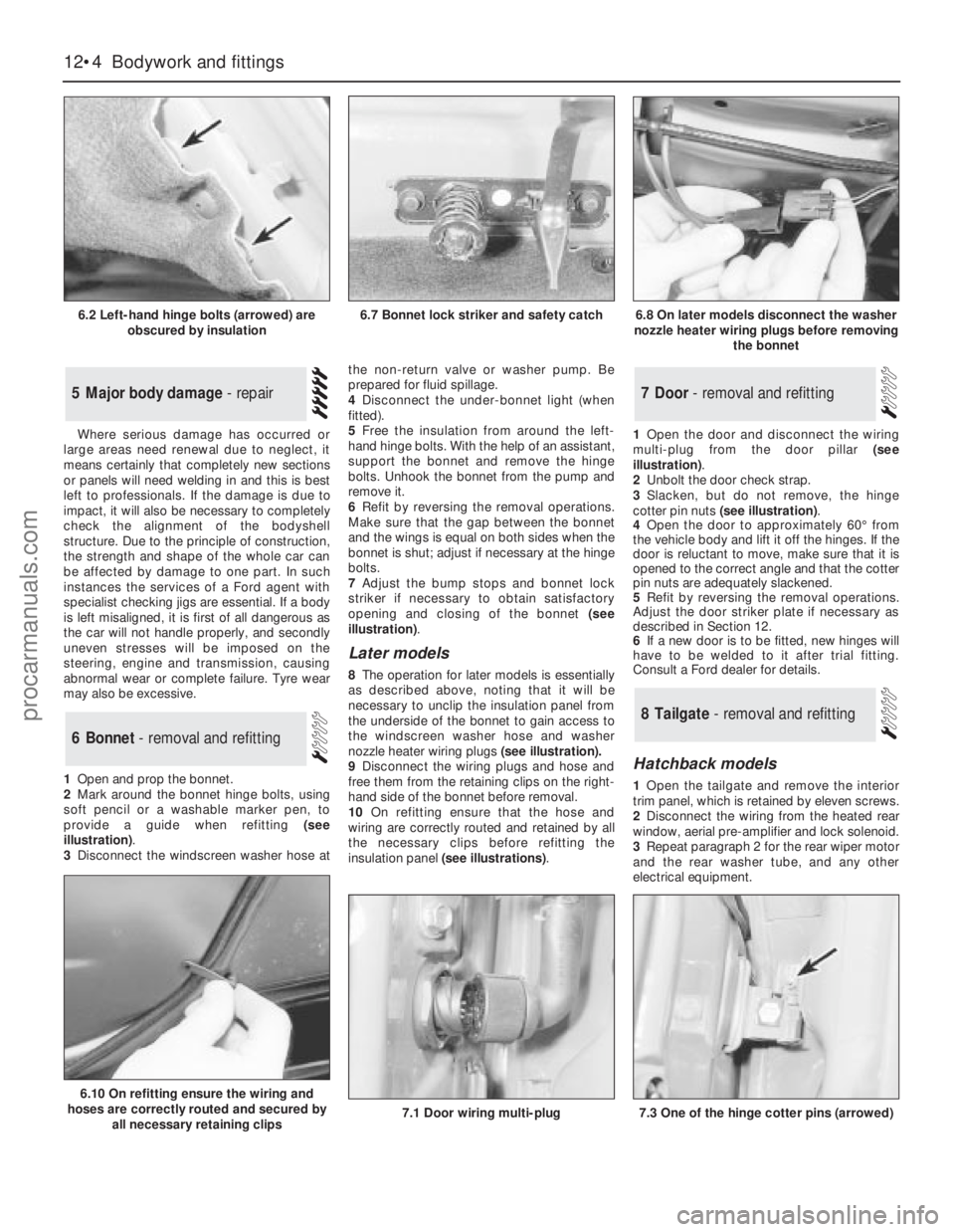
2Mark around the bonnet hinge bolts, using
soft pencil or a washable marker pen, to
provide a guide when refitting (see
illustration).
3Disconnect the windscreen washer hose atthe non-return valve or washer pump. Be
prepared for fluid spillage.
4Disconnect the under-bonnet light (when
fitted).
5Free the insulation from around the left-
hand hinge bolts. With the help of an assistant,
support the bonnet and remove the hinge
bolts. Unhook the bonnet from the pump and
remove it.
6Refit by reversing the removal operations.
Make sure that the gap between the bonnet
and the wings is equal on both sides when the
bonnet is shut; adjust if necessary at the hinge
bolts.
7Adjust the bump stops and bonnet lock
striker if necessary to obtain satisfactory
opening and closing of the bonnet (see
illustration).
Later models
8The operation for later models is essentially
as described above, noting thatit will be
necessary to unclip the insulation panel from
the underside of the bonnet to gain access to
the windscreen washer hose and washer
nozzle heater wiring plugs (see illustration).
9Disconnect the wiring plugs and hose and
free them from the retaining clips on the right-
hand side of the bonnet before removal.
10On refitting ensure that the hose and
wiring are correctly routed and retained by all
the necessary clips before refitting the
insulation panel (see illustrations).1Open the door and disconnect the wiring
multi-plug from the door pillar (see
illustration).
2Unbolt the door check strap.
3Slacken, but do not remove, the hinge
cotter pin nuts (see illustration).
4Open the door to approximately 60°from
the vehicle body and lift it off the hinges. If the
door is reluctant to move, make sure that it is
opened to the correct angle and that the cotter
pin nuts are adequately slackened.
5Refit by reversing the removal operations.
Adjust the door striker plate if necessary as
described in Section 12.
6If a new door is to be fitted, new hinges will
have to be welded to it after trial fitting.
Consult a Ford dealer for details.
Hatchback models
1Open the tailgate and remove the interior
trim panel, which is retained by eleven screws.
2Disconnect the wiring from the heated rear
window, aerial pre-amplifier and lock solenoid.
3Repeat paragraph 2 for the rear wiper motor
and the rear washer tube, and any other
electrical equipment.
8Tailgate - removal and refitting
7Door - removal and refitting
6Bonnet - removal and refitting
5Major body damage - repair
12•4Bodywork and fittings
6.2 Left-hand hinge bolts (arrowed) are
obscured by insulation
6.10 On refitting ensure the wiring and
hoses are correctly routed and secured by
all necessary retaining clips
7.1 Door wiring multi-plug7.3 One of the hinge cotter pins (arrowed)
6.7 Bonnet lock striker and safety catch6.8 On later models disconnect the washer
nozzle heater wiring plugs before removing
the bonnet
procarmanuals.com
Page 162 of 255
4Have an assistant support the tailgate.
Disconnect the struts from the tailgate.
5Jam the tailgate latch with a piece of wood
or cardboard so that the tailgate cannot shut.
Lower the tailgate.
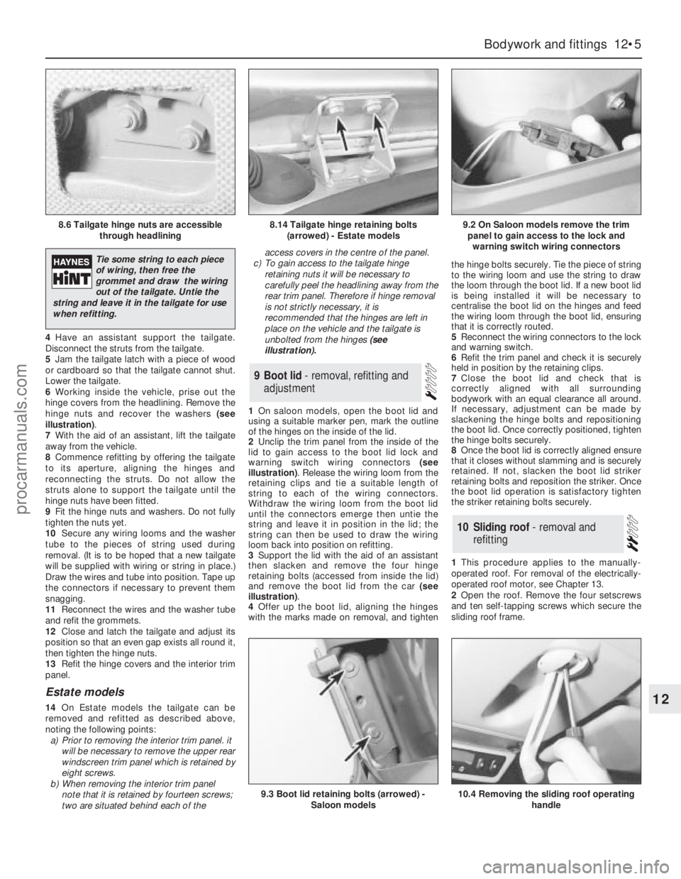
6Working inside the vehicle, prise out the
hinge covers from the headlining. Remove the
hinge nuts and recover the washers (see
illustration).
7With the aid of an assistant, lift the tailgate
away from the vehicle.
8Commence refitting by offering the tailgate
to its aperture, aligning the hinges and
reconnecting the struts. Do not allow the
struts alone to support the tailgate until the
hinge nuts have been fitted.
9Fit the hinge nuts and washers. Do not fully
tighten the nuts yet.
10Secure any wiring looms and the washer
tube to the pieces of string used during
removal. (It is to be hoped that a new tailgate
will be supplied with wiring or string in place.)
Draw the wires and tube into position. Tape up
the connectors if necessary to prevent them
snagging.
11Reconnect the wires and the washer tube
and refit the grommets.
12Close and latch the tailgate and adjust its
position so that an even gap exists all round it,
then tighten the hinge nuts.
13Refit the hinge covers and the interior trim
panel.
Estate models
14On Estate models the tailgate can be
removed and refitted as described above,
noting the following points:
a)Prior to removing the interior trim panel. it
will be necessary to remove the upper rear
windscreen trim panel which is retained by
eight screws.
b)When removing the interior trim panel
note that it is retained by fourteen screws;
two are situated behind each of theaccess covers in the centre of the panel.
c)To gain access to the tailgate hinge
retaining nuts it will be necessary to
carefully peelthe headlining away from the
rear trim panel. Therefore if hinge removal
is not strictly necessary, it is
recommended that the hinges are left in
place on the vehicle and the tailgate is
unbolted from the hinges (see
illustration).
1On saloon models, open the boot lid and
using a suitable marker pen, mark the outline
of the hinges on the inside of the lid.
2Unclip the trim panel from the inside of the
lid to gain access to the boot lid lock and
warning switch wiring connectors (see
illustration). Release the wiring loom from the
retaining clips and tie a suitable length of
string to each of the wiring connectors.
Withdraw the wiring loom from the boot lid
until the connectors emerge then untie the
string and leave it in position in the lid; the
string can then be used to draw the wiring
loom back into position on refitting.
3Support the lid with the aid of an assistant
then slacken and remove the four hinge
retaining bolts (accessed from inside the lid)
and remove the boot lid from the car (see
illustration).
4Offer up the boot lid, aligning the hinges
with the marks made on removal, and tightenthe hinge bolts securely. Tie the piece of string
to the wiring loom and use the string to draw
the loom through the boot lid. If a new boot lid
is being installed it will be necessary to
centralise the boot lid on the hinges and feed
the wiring loom through the boot lid, ensuring
that it is correctly routed.
5Reconnect the wiring connectors to the lock
and warning switch.
6Refit the trim panel and check it is securely
held in position by the retaining clips.
7Close the boot lid and check that is
correctly aligned with all surrounding
bodywork with an equal clearance all around.
If necessary, adjustment can be made by
slackening the hinge bolts and repositioning
the boot lid. Once correctly positioned, tighten
the hinge bolts securely.
8Once the boot lid is correctly aligned ensure
that it closes without slamming and is securely
retained. If not, slacken the boot lid striker
retaining bolts and reposition the striker. Once
the boot lid operation is satisfactory tighten
the striker retaining bolts securely.
1This procedure applies to the manually-
operated roof. For removal of the electrically-
operated roof motor, see Chapter 13.
2Open the roof. Remove the four setscrews
and ten self-tapping screws which secure the
sliding roof frame.
10Sliding roof - removal and
refitting
9Boot lid - removal, refitting and
adjustment
Bodywork and fittings 12•5
12
8.6 Tailgate hinge nuts are accessible
through headlining8.14 Tailgate hinge retaining bolts
(arrowed) - Estate models9.2 On Saloon models remove the trim
panel to gain access to the lock and
warning switch wiring connectors
9.3 Boot lid retaining bolts (arrowed) -
Saloon models10.4 Removing the sliding roof operating
handle
Tie some string to each piece
of wiring, then free the
grommet and draw the wiring
out of the tailgate. Untie the
string and leave it in the tailgate for use
when refitting.
procarmanuals.com
Page 164 of 255
the door through the large cut-out. Further
displacement or removal of the foamrubber
sheet may be necessary.
7Refit in the reverse order to removal, noting
the following points:
a)Apply a little grease to the interior handle
rods where they pass through the plastic
bushes
b)When securing the interior handle, have
the locking lever in the “unlocked”
position, hold the assembly forwards as
far as itwill go and tighten the securing
screw
c)Check all functions before refitting the trim
panel.
Door weatherstrip
1Open the door and remove the weatherstrip
securing screw from the latch end. In the case
of the rear door, also remove the screw from
the hinge end.
2Carefully lift the latch end of the
weatherstrip and pull it off the door.
3Refit by reversing the removal operations,
using your palm to seat the weatherstrip.
Aperture weatherstrip
4Open the door. Remove the scuff plate
securing screws from the bottom of the door
aperture.
5Pull the old weatherstrip out of the door
aperture.
6Fit the new weatherstrip, starting at the
right-angled corner at the top. Fit the
weatherstrip to the other corners and bends,
leaving the straight sections until last.
7Refit the scuff, plate securing screws.
All models except Estate
1Disconnect the battery negative lead.
2Remove the tailgate interior trim panel,
which is secured by eleven screws.
3Remove the six nuts which secure the
tailgate handle. Remove the handle and
recover the gasket.
4Disconnect the tailgate lock switch multi-
plug. Release the switch locking tab and
remove the switch.
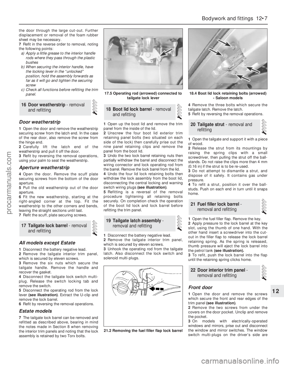
5Disconnect the operating rod from the lock
lever (see illustration). Extract the U-clip and
remove the lock barrel.
6Refit by reversing the removal operations.
Estate models
7The tailgate lock barrel can be removed and
refitted as described above, bearing in mind
the notes made in Section 8 when removing
the interior trim panels and noting that the lock
assembly is retained by two Torx bolts.1Open up the boot lid and remove the trim
panel from the inside of the lid.
2Unscrew the four boot lid exterior trim
retaining panel bolts (two situated on each
side of the lock) then carefully prise out the
nine panel retaining clips and remove the
panel from the boot lid.
3Undo the two lock barrel retaining nuts then
partially withdraw the barrel and disconnect the
wiring connector and lock operating rod from
the barrel. Remove the lock barrel from the lid.
4Undo the four lid lock retaining bolts then
withdraw the lock assembly from the boot lid,
disconnecting the central locking and warning
switch wiring plugs (see illustration).
5Refitting is a reversal of the removal
procedure tightening all retaining bolts
securely. On completion check the operation
of the boot lid lock and lock barrel before
refitting the trim panel.
1Disconnect the battery negative lead.
2Remove the tailgate interior trim panel,
which is secured by eleven screws.
3Unhook the operating rod from the tailgate
latch. Also disconnect the lock switch and
solenoid multi-plugs.4Remove the three bolts which secure the
tailgate latch. Remove the latch.
5Refit by reversing the removal operations.
1Open the tailgate and support it with a piece
of wood.
2Release the strut from its mountings by
raising the spring clips with a small
screwdriver, then pulling the strut off the ball-
stands. Do not raise the clips more than 4 mm
(0.16 in) if the strut is to be re-used.
3Do not attempt to dismantle a strut, and
dispose of it safely. It contains gas under
pressure.
4To refit a strut, position it over the ball-
studs. Push on each end in turn until it snaps
home.
1Open the fuel filler flap. Remove the key.
2Apply pressure to the lock barrel at the key
slot, using the thumb of one hand. With the
other hand insert a screwdriver into the cut-
out in the filler flap to release the lock barrel
retaining spring. As the spring is released,
thumb pressure will eject the lock barrel into
the petrol tank (see illustration).
3To refit, push the lock barrel into the flap
until the retaining spring clicks home.
Front door
1Open the door and remove the screws
which secure the front and rear edges of the
trim panel (see illustration).
2Remove the two screws from under the
covers on the door pocket. Unclip and remove
the pocket.
3On models with electrically-operated
windows and mirrors, prise out and disconnect
the window and mirror switches. The window
switch multi-plugs on the driver’s side are
22Door interior trim panel -
removal and refitting
21Fuel filler lock barrel -
removal and refitting
20Tailgate strut - removal and
refitting
19Tailgate latch assembly -
removal and refitting
18Boot lid lock barrel - removal
and refitting
17Tailgate lock barrel - removal
and refitting
16Door weatherstrip - removal
and refitting
Bodywork and fittings 12•7
12
17.5 Operating rod (arrowed) connected to
tailgate lock lever18.4 Boot lid lock retaining bolts (arrowed)
- Saloon models
21.2 Removing the fuel filler flap lock barrel
procarmanuals.com
Page 166 of 255
5Free the glass from the channels. Carefully
remove the glass upwards through the
window aperture.
6Refit by reversing the removal operations.
Note that the channels are adjustable: wind
the window up and down after securing the
channels and adjust them if necessary for
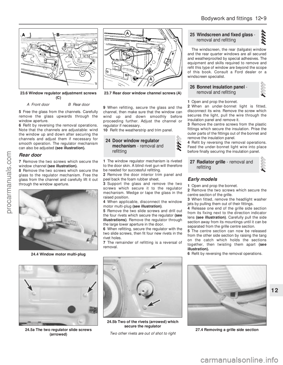
smooth operation. The regulator mechanism
can also be adjusted (see illustration).
Rear door
7Remove the two screws which secure the
window channel (see illustration).
8Remove the two screws which secure the
glass to the regulator mechanism. Free the
glass from the channel and carefully lift it out
through the window aperture.9When refitting, secure the glass and the
channel, then make sure that the window can
wind up and down smoothly before
proceeding further. Adjust the channel or
regulator if necessary.
10Refit the weatherstrip and trim panel.
1The window regulator mechanism is riveted
to the door skin. A blind rivet gun will therefore
be needed for successful refitting.
2Remove the door interior trim panel and
peel back the foam rubber sheet.
3Support the glass and remove the two
screws which secure it to the regulator
mechanism. Wedge or tape the glass in the
raised position.
4When applicable, disconnect the window
motor multi-plug (see illustration).
5Remove the two slide screws and drill out
the four rivets which secure the regulator (see
illustrations). Remove the regulator through
the large lower aperture in the door.
6When refitting, secure the regulator with the
two slide screws, then fit four new rivets in the
rivet holes.
7The remainder of refitting is a reversal of
removal.The windscreen, the rear (tailgate) window
and the rear quarter windows are all secured
and weatherproofed by special adhesives. The
equipment and skills required to remove and
refit this type of window are beyond the scope
of this book. Consult a Ford dealer or a
windscreen specialist.
1Open and prop the bonnet.
2When an under-bonnet light is fitted,
disconnect its wire. Remove the screw which
secures the light, pull the wire through the
insulation panel and remove it.
3Remove the centre screws from the plastic
fittings which secure the insulation. Prise the
outer parts of the fittings out of the bonnet and
remove the insulation panel.
4Refit by reversing the removal operations.
Feed the under-bonnet light wire into place
before finally securing the insulation panel.
Early models
1Open and prop the bonnet.
2Remove the two screws which secure the
centre section of the grille.
3When fitted, remove the headlight washer
jets by pulling them out of their fittings.
4Release one end of the grille side section
from its fixing next to the direction indicator
lens (see illustration). Carefully pull the side
section away from its mountings until it can be
separated from the grille centre section.
5The centre section can now be released
from the other side section by raising the tang
on the catch which holds the sections
together, then twisting them apart (see
illustration).
6Refit by reversing the removal operations.
27Radiator grille - removal and
refitting
26Bonnet insulation panel -
removal and refitting
25Windscreen and fixed glass -
removal and refitting
24Door window regulator
mechanism - removal and
refitting
Bodywork and fittings 12•9
12
23.6 Window regulator adjustment screws
(C)
A Front doorB Rear door
23.7 Rear door window channel screws (A)
24.5a The two regulator slide screws
(arrowed)
24.4 Window motor multi-plug
24.5b Two of the rivets (arrowed) which
secure the regulator
Two other rivets are out of shot to right
27.4 Removing a grille side section
procarmanuals.com
Page 167 of 255
Later models
7The radiator grille of these models can be
removed and refitted as described above,
noting that it will also be necessary to remove
the headlamp wiper arms (where fitted) before
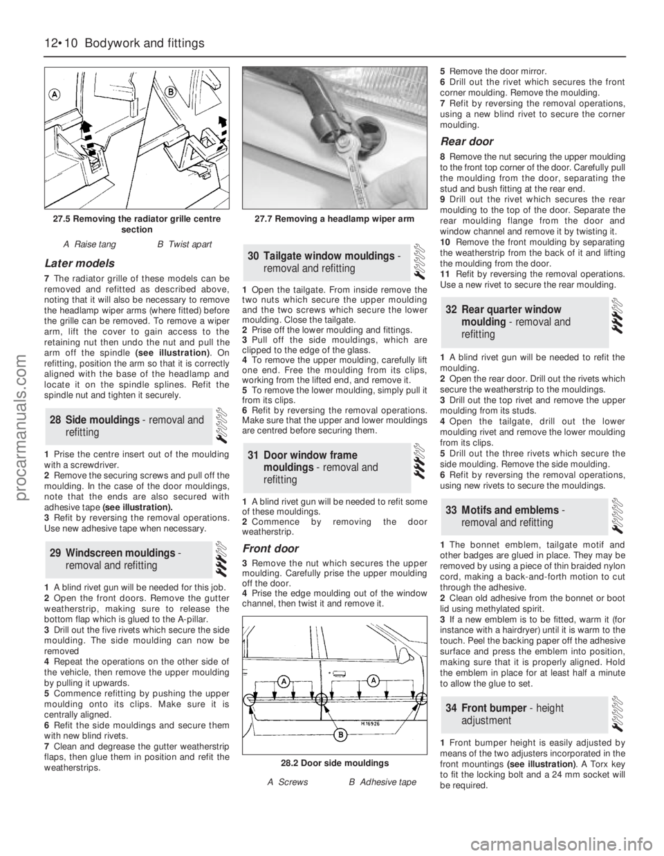
the grille can be removed. To remove a wiper
arm, lift the cover to gain access to the
retaining nut then undo the nut and pull the
arm off the spindle (see illustration). On
refitting, position the arm so that it is correctly
aligned with the base of the headlamp and
locate it on the spindle splines. Refit the
spindle nut and tighten it securely.
1Prise the centre insert out of the moulding
with a screwdriver.
2Remove the securing screws and pull off the
moulding. In the case of the door mouldings,
note that the ends are also secured with
adhesive tape (see illustration).
3Refit by reversing the removal operations.
Use new adhesive tape when necessary.
1A blind rivet gun will be needed for this job.
2Open the front doors. Remove the gutter
weatherstrip, making sure to release the
bottom flap which is glued to the A-pillar.
3Drill out the five rivets which secure the side
moulding. The side moulding can now be
removed
4Repeat the operations on the other side of
the vehicle, then remove the upper moulding
by pulling it upwards.
5Commence refitting by pushing the upper
moulding onto its clips. Make sure it is
centrally aligned.
6Refit the side mouldings and secure them
with new blind rivets.
7Clean and degrease the gutter weatherstrip
flaps, then glue them in position and refit the
weatherstrips.1Open the tailgate. From inside remove the
two nuts which secure the upper moulding
and the two screws which secure the lower
moulding. Close the tailgate.
2Prise off the lower moulding and fittings.
3Pull off the side mouldings, which are
clipped to the edge of the glass.
4To remove the upper moulding, carefully lift
one end. Free the moulding from its clips,
working from the lifted end, and remove it.
5To remove the lower moulding, simply pull it
from its clips.
6Refit by reversing the removal operations.
Make sure that the upper and lower mouldings
are centred before securing them.
1A blind rivet gun will be needed to refit some
of these mouldings.
2Commence by removing the door
weatherstrip.
Front door
3Remove the nut which secures the upper
moulding. Carefully prise the upper moulding
off the door.
4Prise the edge moulding out of the window
channel, then twist it and remove it. 5Remove the door mirror.
6Drill out the rivet which secures the front
corner moulding. Remove the moulding.
7Refit by reversing the removal operations,
using a new blind rivet to secure the corner
moulding.
Rear door
8Remove the nut securing the upper moulding
to the front top corner of the door. Carefully pull
the moulding from the door, separating the
stud and bush fitting at the rear end.
9Drill out the rivet which secures the rear
moulding to the top of the door. Separate the
rear moulding flange from the door and
window channel and remove it by twisting it.
10Remove the front moulding by separating
the weatherstrip from the back of it and lifting
the moulding from the door.
11Refit by reversing the removal operations.
Use a new rivet to secure the rear moulding.
1A blind rivet gun will be needed to refit the
moulding.
2Open the rear door. Drill out the rivets which
secure the weatherstrip to the mouldings.
3Drill out the top rivet and remove the upper
moulding from its studs.
4Open the tailgate, drill out the lower
moulding rivet and remove the lower moulding
from its clips.
5Drill out the three rivets which secure the
side moulding. Remove the side moulding.
6Refit by reversing the removal operations,
using new rivets to secure the mouldings.
1The bonnet emblem, tailgate motif and
other badges are glued in place. They may be
removed by using a piece of thin braided nylon
cord, making a back-and-forth motion to cut
through the adhesive.
2Clean old adhesive from the bonnet or boot
lid using methylated spirit.
3If a new emblem is to be fitted, warm it (for
instance with a hairdryer) until it is warm to the
touch. Peel the backing paper off the adhesive
surface and press the emblem into position,
making sure that it is properly aligned. Hold
the emblem in place for at least half a minute
to allow the glue to set.
1Front bumper height is easily adjusted by
means of the two adjusters incorporated in the
front mountings (see illustration). A Torx key
to fit the locking bolt and a 24 mm socket will
be required.
34Front bumper - height
adjustment
33Motifs and emblems -
removal and refitting
32Rear quarter window
moulding - removal and
refitting
31Door window frame
mouldings - removal and
refitting
30Tailgate window mouldings -
removal and refitting
29Windscreen mouldings -
removal and refitting
28Side mouldings - removal and
refitting
12•10Bodywork and fittings
27.5 Removing the radiator grille centre
section
A Raise tangB Twist apart
27.7 Removing a headlamp wiper arm
28.2 Door side mouldings
A ScrewsB Adhesive tape
procarmanuals.com