1985 FORD GRANADA seats
[x] Cancel search: seatsPage 35 of 255
mountings to the front crossmember. Recover
the washers.
3Raise the engine with a hoist or a suitable
protected jack until the mountings are free,
then remove them.
4Fit the new mountings and lower the engine
onto them.
5Fit the nuts and washers and tighten the
nuts.
6Lower the vehicle.
Carburettor models
The crankcase ventilation system consists
of the special oil filter cap (containing a steel
wool filter) and an oil separator and vent valve
on the left-hand side of the engine. This is
connected by hose to the inlet manifold. The
system operates according to the vacuum in
the inlet manifold. Air is drawn through the
filler cap, through the crankcase, and then
together with piston blow-by gasses through
the oil separator and vent valve to the inlet
manifold. The blow-by gases are then drawn
into the engine together with the fuel/air
mixture. Refer to Chapter 1 for maintenance of
the system.
Fuel-injection models
This system is closed, consisting of an oilseparator on the left-hand side of the engine
and a hose connecting it to the inlet air
trunking. Because the trunking is not subject
to manifold vacuum, no vent valve is needed.
1With the engine completely stripped, clean
all the components and examine them for
wear. Each part should be checked, and
where necessary renewed or renovated as
described in the following Sections. Renew
main and big end shell bearings as a matter of
course, unless you know that they have had
little wear and are in perfect condition.
2If in doubt as to whether to renew a
component which is still just serviceable,
consider the time and effort which will be
incurred should it fail at an early date.
Obviously the age and expected life of the
vehicle must influence the standards applied.
3Gaskets, oil seals and O-rings must all be
renewed as a matter of routine. Flywheel and
cylinder head bolts must be renewed because
of the high stresses to which they are
subjected.
4Take the opportunity to renew the engine
core plugs while they are easily accessible.
Knock out the old plugs with a hammer and
chisel or punch. Clean the plug seats, smear
the new plugs with sealant and tap them
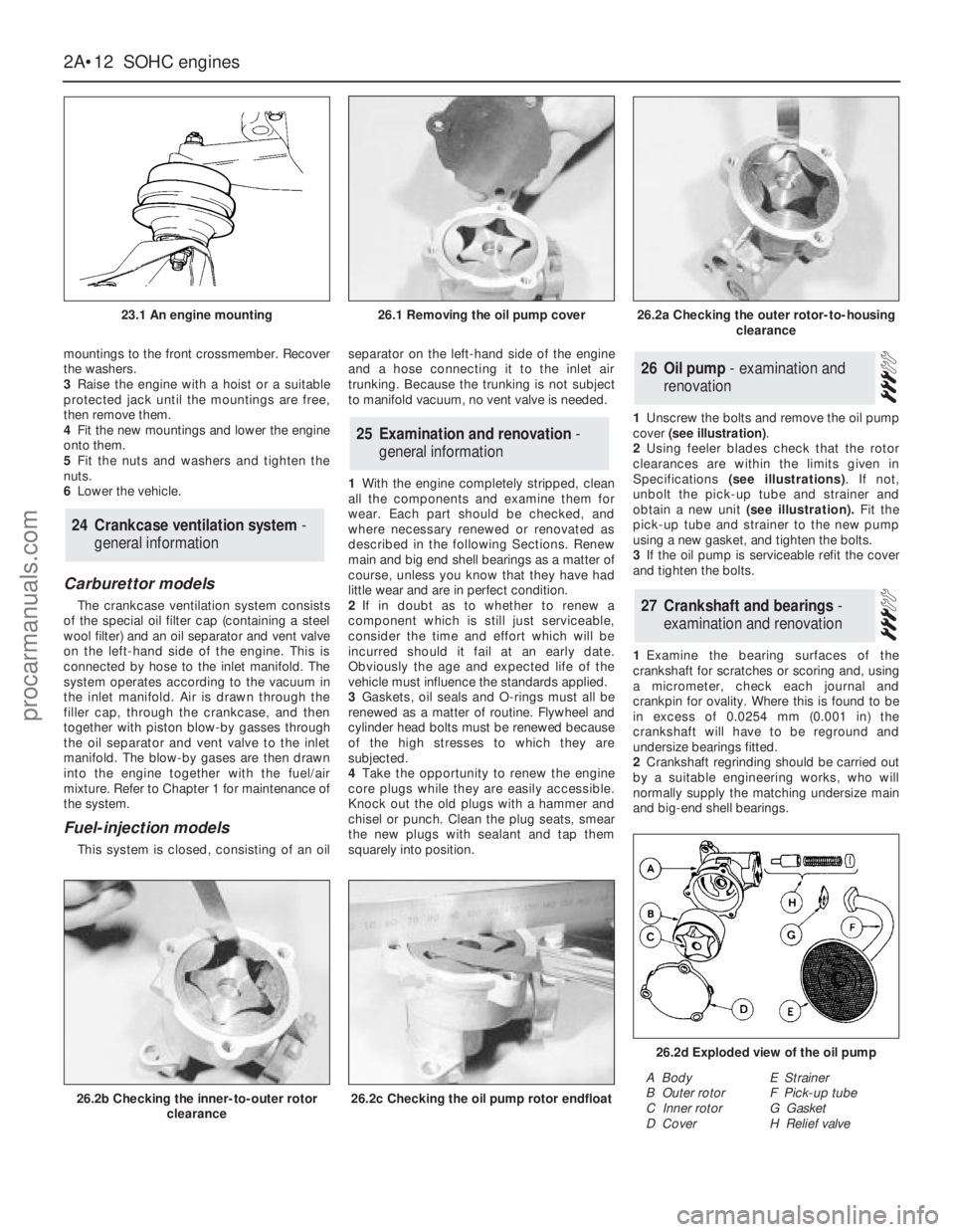
squarely into position.1Unscrew the bolts and remove the oil pump
cover (see illustration).
2Using feeler blades check that the rotor
clearances are within the limits given in
Specifications (see illustrations). If not,
unbolt the pick-up tube and strainer and
obtain a new unit (see illustration).Fit the
pick-up tube and strainer to the new pump
using a new gasket, and tighten the bolts.
3If the oil pump is serviceable refit the cover
and tighten the bolts.
1Examine the bearing surfaces of the
crankshaft for scratches or scoring and, using
a micrometer, check each journal and
crankpin for ovality. Where this is found to be
in excess of 0.0254 mm (0.001 in) the
crankshaft will have to be reground and
undersize bearings fitted.
2Crankshaft regrinding should be carried out
by a suitable engineering works, who will
normally supply the matching undersize main
and big-end shell bearings.
27Crankshaft and bearings -
examination and renovation
26Oil pump - examination and
renovation
25Examination and renovation -
general information
24Crankcase ventilation system -
general information
2A•12SOHCengines
23.1 An engine mounting
26.2b Checking the inner-to-outer rotor
clearance26.2c Checking the oil pump rotor endfloat
26.2d Exploded view of the oil pump
A Body
B Outer rotor
C Inner rotor
D CoverE Strainer
F Pick-up tube
G Gasket
H Relief valve
26.1 Removing the oil pump cover26.2a Checking the outer rotor-to-housing
clearance
procarmanuals.com
Page 37 of 255
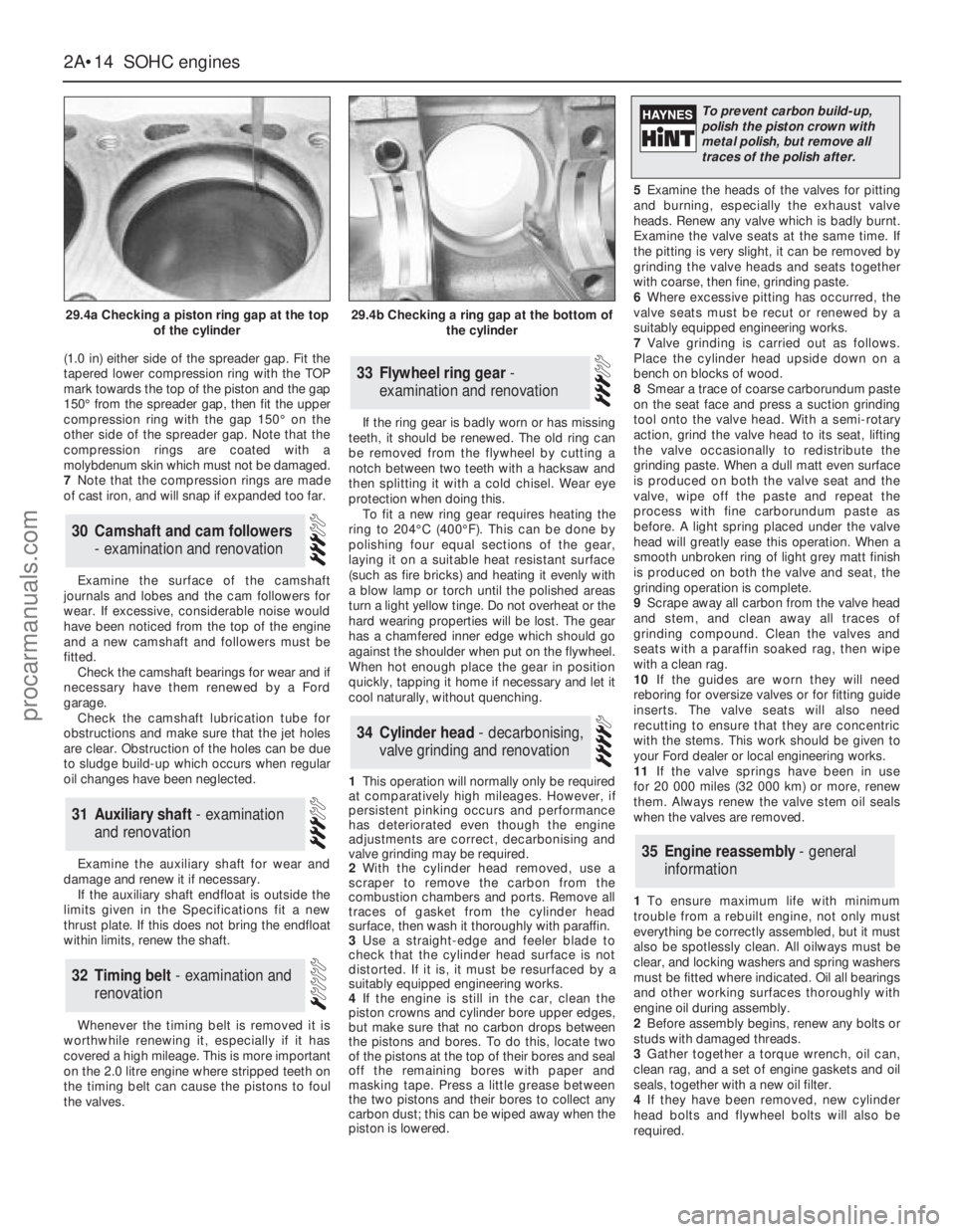
(1.0 in) either side of the spreader gap. Fit the
tapered lower compression ring with the TOP
mark towards the top of the piston and the gap
150°from the spreader gap, then fit the upper
compression ring with the gap 150°on the
other side of the spreader gap. Note that the
compression rings are coated with a
molybdenum skin which must not be damaged.
7Note that the compression rings are made
of cast iron, and will snap if expanded too far.
Examine the surface of the camshaft
journals and lobes and the cam followers for
wear. If excessive, considerable noise would
have been noticed from the top of the engine
and a new camshaft and followers must be
fitted.
Check the camshaft bearings for wear and if
necessary have them renewed by a Ford
garage.
Check the camshaft lubrication tube for
obstructions and make sure that the jet holes
are clear. Obstruction of the holes can be due
to sludge build-up which occurs when regular
oil changes have been neglected.
Examine the auxiliary shaft for wear and
damage and renew it if necessary.
If the auxiliary shaft endfloat is outside the
limits given in the Specifications fit a new
thrust plate. If this does not bring the endfloat
within limits, renew the shaft.
Whenever the timing belt is removed it is
worthwhile renewing it, especially if it has
covered a high mileage. This is more important
on the 2.0 litre engine where stripped teeth on
the timing belt can cause the pistons to foul
the valves.If the ring gear is badly worn or has missing
teeth, it should be renewed. The old ring can
be removed from the flywheel by cutting a
notch between two teeth with a hacksaw and
then splitting it with a cold chisel. Wear eye
protection when doing this.
To fit a new ring gear requires heating the
ring to 204°C (400°F). This can be done by
polishing four equal sections of the gear,
laying it on a suitable heat resistant surface
(such as fire bricks) and heating it evenly with
a blow lamp or torch until the polished areas
turn a light yellow tinge. Do not overheat or the
hard wearing properties will be lost. The gear
has a chamfered inner edge which should go
against the shoulder when put on the flywheel.
When hot enough place the gear in position
quickly, tapping it home if necessary and let it
cool naturally, without quenching.
1This operation will normally only be required
at comparatively high mileages. However, if
persistent pinking occurs and performance
has deteriorated even though the engine
adjustments are correct, decarbonising and
valve grinding may be required.
2With the cylinder head removed, use a
scraper to remove the carbon from the
combustion chambers and ports. Remove all
traces of gasket from the cylinder head
surface, then wash it thoroughly with paraffin.
3Use a straight-edge and feeler blade to
check that the cylinder head surface is not
distorted. If it is, it must be resurfaced by a
suitably equipped engineering works.
4If the engine is still in the car, clean the
piston crowns and cylinder bore upper edges,
but make sure that no carbon drops between
the pistons and bores. To do this, locate two
of the pistons at the top of their bores and seal
off the remaining bores with paper and
masking tape. Press a little grease between
the two pistons and their bores to collect any
carbon dust; this can be wiped away when the
piston is lowered.5Examine the heads of the valves for pitting
and burning, especially the exhaust valve
heads. Renew any valve which is badly burnt.
Examine the valve seats at the same time. If
the pitting is very slight, it can be removed by
grinding the valve heads and seats together
with coarse, then fine, grinding paste.
6Where excessive pitting has occurred, the
valve seats must be recut or renewed by a
suitably equipped engineering works.
7Valve grinding is carried out as follows.
Place the cylinder head upside down on a
bench on blocks of wood.
8Smear a trace of coarse carborundum paste
on the seat face and press a suction grinding
tool onto the valve head. With a semi-rotary
action, grind the valve head to its seat, lifting
the valve occasionally to redistribute the
grinding paste. When a dull matt even surface
is produced on both the valve seat and the
valve, wipe off the paste and repeat the
process with fine carborundum paste as
before. A light spring placed under the valve
head will greatly ease this operation. When a
smooth unbroken ring of light grey matt finish
is produced on both the valve and seat, the
grinding operation is complete.
9Scrape away all carbon from the valve head
and stem, and clean away all traces of
grinding compound. Clean the valves and
seats with a paraffin soaked rag, then wipe
with a clean rag.
10If the guides are worn they will need
reboring for oversize valves or for fitting guide
inserts. The valve seats will also need
recutting to ensure that they are concentric
with the stems. This work should be given to
your Ford dealer or local engineering works.
11If the valve springs have been in use
for 20 000 miles (32 000 km) or more, renew
them. Always renew the valve stem oil seals
when the valves are removed.
1To ensure maximum life with minimum
trouble from a rebuilt engine, not only must
everything be correctly assembled, but it must
also be spotlessly clean. All oilways must be
clear, and locking washers and spring washers
must be fitted where indicated. Oil all bearings
and other working surfaces thoroughly with
engine oil during assembly.
2Before assembly begins, renew any bolts or
studs with damaged threads.
3Gather together a torque wrench, oil can,
clean rag, and a set of engine gaskets and oil
seals, together with a new oil filter.
4If they have been removed, new cylinder
head bolts and flywheel bolts will also be
required.
35Engine reassembly - general
information
34Cylinder head - decarbonising,
valve grinding and renovation
33Flywheel ring gear -
examination and renovation
32Timing belt - examination and
renovation
31Auxiliary shaft - examination
and renovation
30Camshaft and cam followers
- examination and renovation
2A•14SOHCengines
29.4a Checking a piston ring gap at the top
of the cylinder29.4b Checking a ring gap at the bottom of
the cylinder
To prevent carbon build-up,
polish the piston crown with
metal polish, but remove all
traces of the polish after.
procarmanuals.com
Page 73 of 255
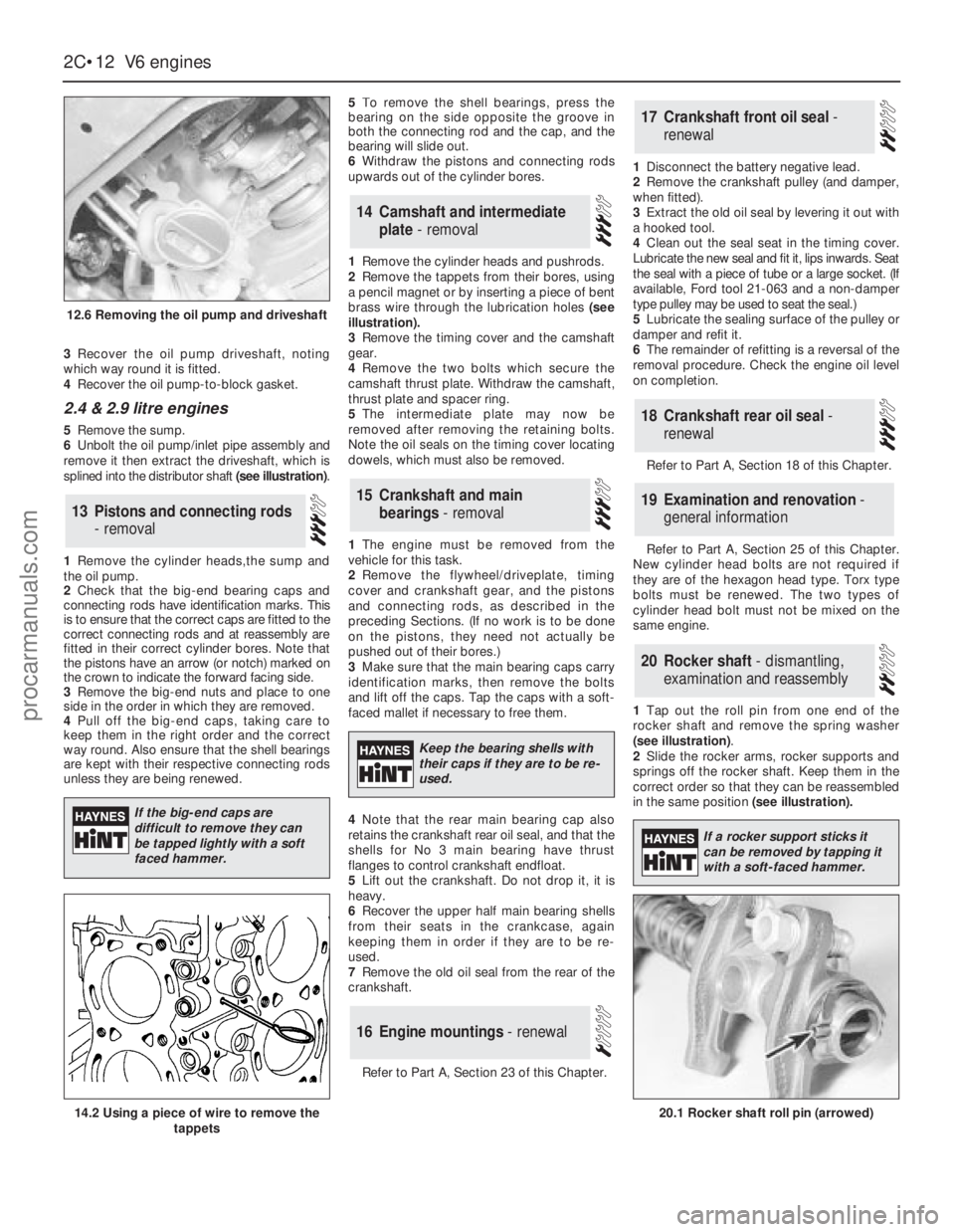
3Recover the oil pump driveshaft, noting
which way round it is fitted.
4Recover the oil pump-to-block gasket.
2.4 & 2.9 litre engines
5Remove the sump.
6Unbolt the oil pump/inlet pipe assembly and
remove it then extract the driveshaft, which is
splined into the distributor shaft (see illustration).
1Remove the cylinder heads,the sump and
the oil pump.
2Check that the big-end bearing caps and
connecting rods have identification marks. This
is to ensure that the correct caps are fitted to the
correct connecting rods and at reassembly are
fitted in their correct cylinder bores. Note that
the pistons have an arrow (or notch) marked on
the crown to indicate the forward facing side.
3Remove the big-end nuts and place to one
side in the order in which they are removed.
4Pull off the big-end caps, taking care to
keep them in the right order and the correct
way round. Also ensure that the shell bearings
are kept with their respective connecting rods
unless they are being renewed.5To remove the shell bearings, press the
bearing on the side opposite the groove in
both the connecting rod and the cap, and the
bearing will slide out.
6Withdraw the pistons and connecting rods
upwards out of the cylinder bores.
1Remove the cylinder heads and pushrods.
2Remove the tappets from their bores, using
a pencil magnet or by inserting a piece of bent
brass wire through the lubrication holes (see
illustration).
3Remove the timing cover and the camshaft
gear.
4Remove the two bolts which secure the
camshaft thrust plate. Withdraw the camshaft,
thrust plate and spacer ring.
5The intermediate plate may now be
removed after removing the retaining bolts.
Note the oil seals on the timing cover locating
dowels, which must also be removed.
1The engine must be removed from the
vehicle for this task.
2Remove the flywheel/driveplate, timing
cover and crankshaft gear, and the pistons
and connecting rods, as described in the
preceding Sections. (If no work is to be done
on the pistons, they need not actually be
pushed out of their bores.)
3Make sure that the main bearing caps carry
identification marks, then remove the bolts
and lift off the caps. Tap the caps with a soft-
faced mallet if necessary to free them.
4Note that the rear main bearing cap also
retains the crankshaft rear oil seal, and that the
shells for No 3 main bearing have thrust
flanges to control crankshaft endfloat.
5Lift out the crankshaft. Do not drop it, it is
heavy.
6Recover the upper half main bearing shells
from their seats in the crankcase, again
keeping them in order if they are to be re-
used.
7Remove the old oil seal from the rear of the
crankshaft.
Refer to Part A, Section 23 of this Chapter.1Disconnect the battery negative lead.
2Remove the crankshaft pulley (and damper,
when fitted).
3Extract the old oil seal by levering it out with
a hooked tool.
4Clean out the seal seat in the timing cover.
Lubricate the new seal and fit it, lips inwards. Seat
the seal with a piece of tube or a large socket. (If
available, Ford tool 21-063 and a non-damper
type pulley may be used to seat the seal.)
5Lubricate the sealing surface of the pulley or
damper and refit it.
6The remainder of refitting is a reversal of the
removal procedure. Check the engine oil level
on completion.
Refer to Part A, Section 18 of this Chapter.
Refer to Part A, Section 25 of this Chapter.
New cylinder head bolts are not required if
they are of the hexagon head type. Torx type
bolts must be renewed. The two types of
cylinder head bolt must not be mixed on the
same engine.
1Tap out the roll pin from one end of the
rocker shaft and remove the spring washer
(see illustration).
2Slide the rocker arms, rocker supports and
springs off the rocker shaft. Keep them in the
correct order so that they can be reassembled
in the same position (see illustration).
20Rocker shaft - dismantling,
examination and reassembly
19Examination and renovation -
general information
18Crankshaft rear oil seal -
renewal
17Crankshaft front oil seal -
renewal
16Engine mountings - renewal
15Crankshaft and main
bearings - removal
14Camshaft and intermediate
plate - removal
13Pistons and connecting rods
- removal
2C•12V6 engines
12.6 Removing the oil pump and driveshaft
20.1 Rocker shaft roll pin (arrowed)14.2 Using a piece of wire to remove the
tappets
If the big-end caps are
difficult to remove they can
be tapped lightly with a soft
faced hammer.
Keep the bearing shells with
their caps if they are to be re-
used.
If a rocker support sticks it
can be removed by tapping it
with a soft-faced hammer.
procarmanuals.com
Page 74 of 255
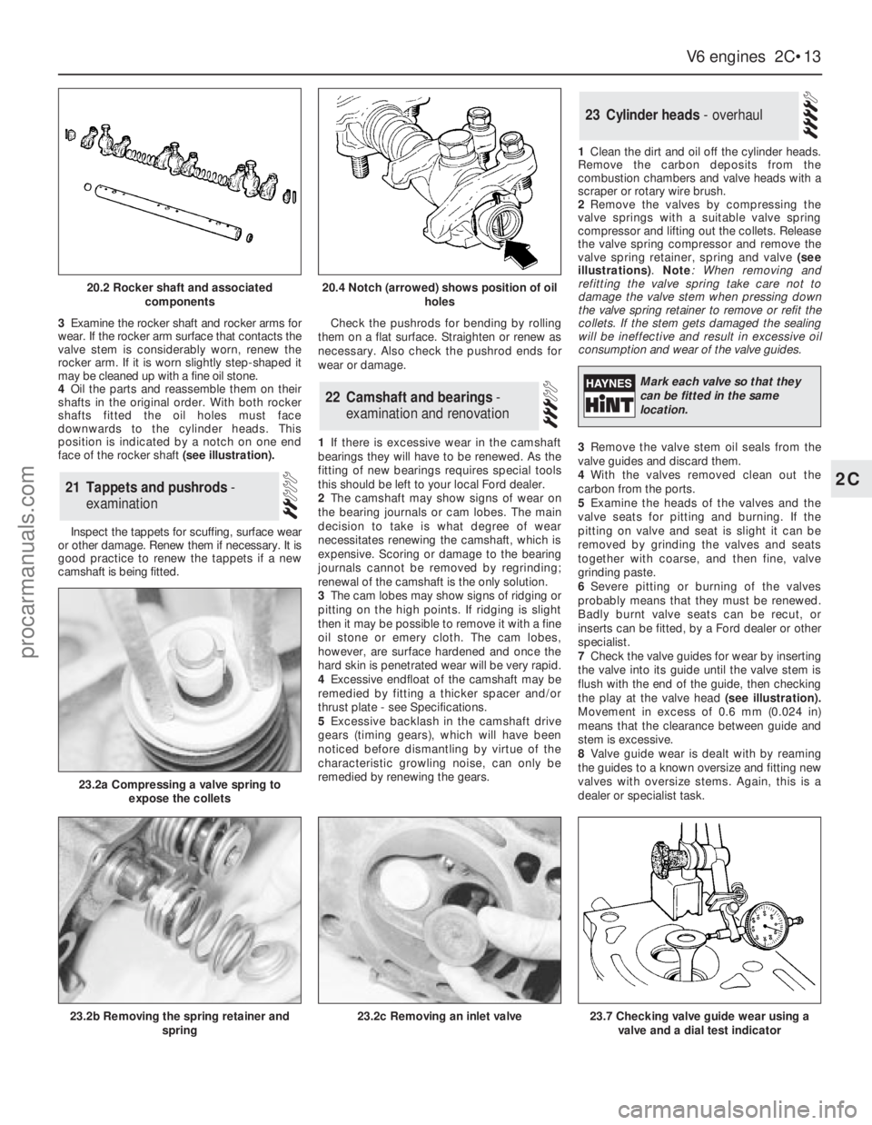
3Examine the rocker shaft and rocker arms for
wear. If the rocker arm surface that contacts the
valve stem is considerably worn, renew the
rocker arm. If it is worn slightly step-shaped it
may be cleaned up with a fine oil stone.
4Oil the parts and reassemble them on their
shafts in the original order. With both rocker
shafts fitted the oil holes must face
downwards to the cylinder heads. This
position is indicated by a notch on one end
face of the rocker shaft (see illustration).
Inspect the tappets for scuffing, surface wear
or other damage. Renew them if necessary. It is
good practice to renew the tappets if a new
camshaft is being fitted.Check the pushrods for bending by rolling
them on a flat surface. Straighten or renew as
necessary. Also check the pushrod ends for
wear or damage.
1If there is excessive wear in the camshaft
bearings they will have to be renewed. As the
fitting of new bearings requires special tools
this should be left to your local Ford dealer.
2The camshaft may show signs of wear on
the bearing journals or cam lobes. The main
decision to take is what degree of wear
necessitates renewing the camshaft, which is
expensive. Scoring or damage to the bearing
journals cannot be removed by regrinding;
renewal of the camshaft is the only solution.
3The cam lobes may show signs of ridging or
pitting on the high points. If ridging is slight
then it may be possible to remove it with a fine
oil stone or emery cloth. The cam lobes,
however, are surface hardened and once the
hard skin is penetrated wear will be very rapid.
4Excessive endfloat of the camshaft may be
remedied by fitting a thicker spacer and/or
thrust plate - see Specifications.
5Excessive backlash in the camshaft drive
gears (timing gears), which will have been
noticed before dismantling by virtue of the
characteristic growling noise, can only be
remedied by renewing the gears.1Clean the dirt and oil off the cylinder heads.
Remove the carbon deposits from the
combustion chambers and valve heads with a
scraper or rotary wire brush.
2Remove the valves by compressing the
valve springs with a suitable valve spring
compressor and lifting out the collets. Release
the valve spring compressor and remove the
valve spring retainer, spring and valve (see
illustrations).Note: When removing and
refitting the valve spring take care not to
damage the valve stem when pressing down
the valve spring retainer to remove or refit the
collets. If the stem gets damaged the sealing
will be ineffective and result in excessive oil
consumption and wear of the valve guides.
3Remove the valve stem oil seals from the
valve guides and discard them.
4With the valves removed clean out the
carbon from the ports.
5Examine the heads of the valves and the
valve seats for pitting and burning. If the
pitting on valve and seat is slight it can be
removed by grinding the valves and seats
together with coarse, and then fine, valve
grinding paste.
6Severe pitting or burning of the valves
probably means that they must be renewed.
Badly burnt valve seats can be recut, or
inserts can be fitted, by a Ford dealer or other
specialist.
7Check the valve guides for wear by inserting
the valve into its guide until the valve stem is
flush with the end of the guide, then checking
the play at the valve head(see illustration).
Movement in excess of 0.6 mm (0.024 in)
means that the clearance between guide and
stem is excessive.
8Valve guide wear is dealt with by reaming
the guides to a known oversize and fitting new
valves with oversize stems. Again, this is a
dealer or specialist task.
23Cylinder heads - overhaul
22Camshaft and bearings -
examination and renovation
21Tappets and pushrods -
examination
V6 engines 2C•13
2C
20.2 Rocker shaft and associated
components20.4 Notch (arrowed) shows position of oil
holes
23.2a Compressing a valve spring to
expose the collets
23.2b Removing the spring retainer and
spring23.2c Removing an inlet valve23.7 Checking valve guide wear using a
valve and a dial test indicator
Mark each valve so that they
can be fitted in the same
location.
procarmanuals.com
Page 77 of 255
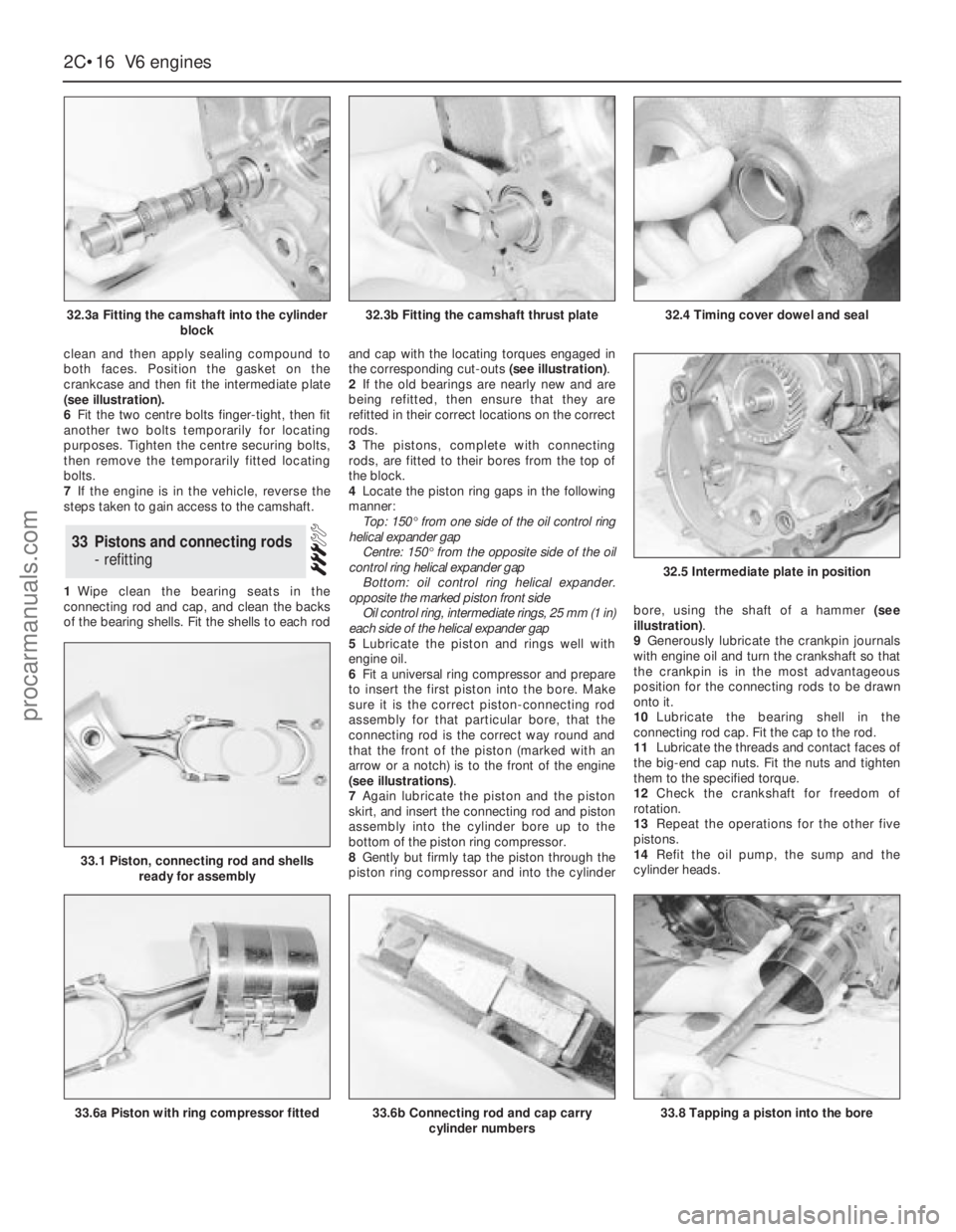
clean and then apply sealing compound to
both faces. Position the gasket on the
crankcase and then fit the intermediate plate
(see illustration).
6Fit the two centre bolts finger-tight, then fit
another two bolts temporarily for locating
purposes. Tighten the centre securing bolts,
then remove the temporarily fitted locating
bolts.
7If the engine is in the vehicle, reverse the
steps taken to gain access to the camshaft.
1Wipe clean the bearing seats in the
connecting rod and cap, and clean the backs
of the bearing shells. Fit the shells to each rodand cap with the locating torques engaged in
the corresponding cut-outs (see illustration).
2If the old bearings are nearly new and are
being refitted, then ensure that they are
refitted in their correct locations on the correct
rods.
3The pistons, complete with connecting
rods, are fitted to their bores from the top of
the block.
4Locate the piston ring gaps in the following
manner:
Top: 150°from one side of the oil control ring
helical expander gap
Centre: 150°from the opposite side of the oil
control ring helical expander gap
Bottom: oil control ring helical expander.
opposite the marked piston front side
Oil control ring, intermediate rings, 25 mm (1 in)
each side of the helical expander gap
5Lubricate the piston and rings well with
engine oil.
6Fit a universal ring compressor and prepare
to insert the first piston into the bore. Make
sure it is the correct piston-connecting rod
assembly for that particular bore, that the
connecting rod is the correct way round and
that the front of the piston (marked with an
arrow or a notch) is to the front of the engine
(see illustrations).
7Again lubricate the piston and the piston
skirt, and insert the connecting rod and piston
assembly into the cylinder bore up to the
bottom of the piston ring compressor.
8Gently but firmly tap the piston through the
piston ring compressor and into the cylinderbore, using the shaft of a hammer (see
illustration).
9Generously lubricate the crankpin journals
with engine oil and turn the crankshaft so that
the crankpin is in the most advantageous
position for the connecting rods to be drawn
onto it.
10Lubricate the bearing shell in the
connecting rod cap. Fit the cap to the rod.
11Lubricate the threads and contact faces of
the big-end cap nuts. Fit the nuts and tighten
them to the specified torque.
12Check the crankshaft for freedom of
rotation.
13Repeat the operations for the other five
pistons.
14Refit the oil pump, the sump and the
cylinder heads.
33Pistons and connecting rods
- refitting
2C•16V6 engines
32.3a Fitting the camshaft into the cylinder
block
33.6a Piston with ring compressor fitted
32.5 Intermediate plate in position
33.6b Connecting rod and cap carry
cylinder numbers33.8 Tapping a piston into the bore
33.1 Piston, connecting rod and shells
ready for assembly
32.3b Fitting the camshaft thrust plate32.4 Timing cover dowel and seal
procarmanuals.com
Page 116 of 255
Models up to July 1990
1The carbon canister is situated in the engine
compartment where it is mounted onto the
right-hand valance next to the suspension
strut mounting.
2To remove the canister first disconnect the
battery negative terminal. If necessary, undo
the two coolant expansion tank retaining
screws and position the tank clear of the
canister to improve access.
3Disconnect the vacuum hose from the top
of the canister.
4Slacken and remove the mounting bolt and
withdraw the canister from the engine
compartment.
5Refitting is a reverse of the removal
procedure.
Models from July 1990
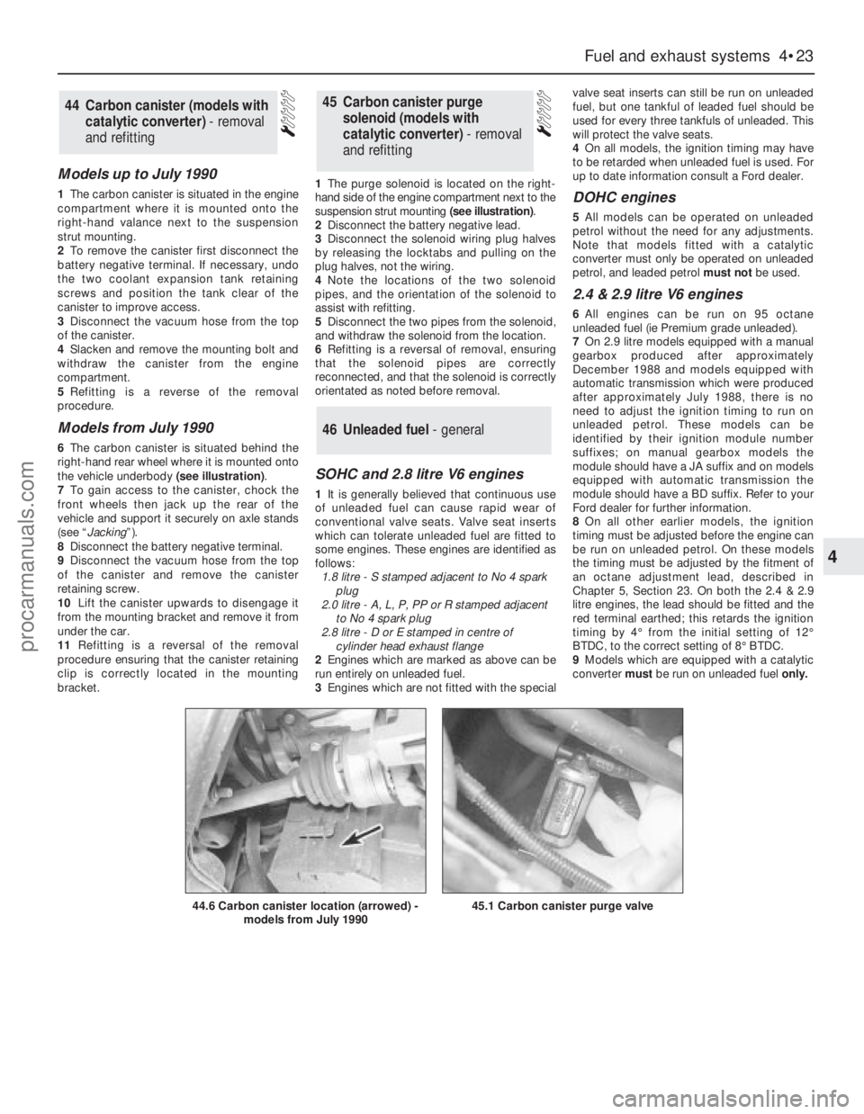
6The carbon canister is situated behind the
right-hand rear wheel where it is mounted onto
the vehicle underbody (see illustration).
7To gain access to the canister, chock the
front wheels then jack up the rear of the
vehicle and support it securely on axle stands
(see “Jacking”).
8Disconnect the battery negative terminal.
9Disconnect the vacuum hose from the top
of the canister and remove the canister
retaining screw.
10Lift the canister upwards to disengage it
from the mounting bracket and remove it from
under the car.
11Refitting is a reversal of the removal
procedure ensuring that the canister retaining
clip is correctly located in the mounting
bracket.1The purge solenoid is located on the right-
hand side of the engine compartment next to the
suspension strut mounting (see illustration).
2Disconnect the battery negative lead.
3Disconnect the solenoid wiring plug halves
by releasing the locktabs and pulling on the
plug halves, not the wiring.
4Note the locations of the two solenoid
pipes, and the orientation of the solenoid to
assist with refitting.
5Disconnect the two pipes from the solenoid,
and withdraw the solenoid from the location.
6Refitting is a reversal of removal, ensuring
that the solenoid pipes are correctly
reconnected, and that the solenoid is correctly
orientated as noted before removal.
SOHC and 2.8 litre V6 engines
1It is generally believed that continuous use
of unleaded fuel can cause rapid wear of
conventional valve seats. Valve seat inserts
which can tolerate unleaded fuel are fitted to
some engines. These engines are identified as
follows:
1.8 litre - S stamped adjacent to No 4 spark
plug
2.0 litre - A, L, P, PP or R stamped adjacent
to No 4 spark plug
2.8 litre - D or E stamped in centre of
cylinder head exhaust flange
2Engines which are marked as above can be
run entirely on unleaded fuel.
3Engines which are not fitted with the specialvalve seat inserts can still be run on unleaded
fuel, but one tankful of leaded fuel should be
used for every three tankfuls of unleaded. This
will protect the valve seats.
4On all models, the ignition timing may have
to be retarded when unleaded fuel is used. For
up to date information consult a Ford dealer.
DOHC engines
5All models can be operated on unleaded
petrol without the need for any adjustments.
Note that models fitted with a catalytic
converter must only be operated on unleaded
petrol, and leaded petrol must notbe used.
2.4 & 2.9 litre V6 engines
6All engines can be run on 95 octane
unleaded fuel (ie Premium grade unleaded).
7On 2.9 litre models equipped with a manual
gearbox produced after approximately
December 1988 and models equipped with
automatic transmission which were produced
after approximately July 1988, there is no
need to adjust the ignition timing to run on
unleaded petrol. These models can be
identified by their ignition module number
suffixes; on manual gearbox models the
module should have a JA suffix and on models
equipped with automatic transmission the
module should have a BD suffix. Refer to your
Ford dealer for further information.
8On all other earlier models, the ignition
timing must be adjusted before the engine can
be run on unleaded petrol. On these models
the timing must be adjusted by the fitment of
an octane adjustment lead, described in
Chapter 5, Section 23. On both the 2.4 & 2.9
litre engines, the lead should be fitted and the
red terminal earthed; this retards the ignition
timing by 4°from the initial setting of 12°
BTDC, to the correct setting of 8°BTDC.
9Models which are equipped with a catalytic
converter must be run on unleaded fuel only.
46Unleaded fuel - general
45Carbon canister purge
solenoid (models with
catalytic converter) - removal
and refitting44Carbon canister (models with
catalytic converter) - removal
and refitting
Fuel and exhaust systems 4•23
4
44.6 Carbon canister location (arrowed) -
models from July 199045.1 Carbon canister purge valve
procarmanuals.com
Page 151 of 255
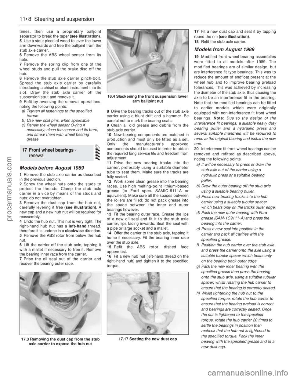
times, then use a proprietary balljoint
separator to break the taper (see illustration).
5Use a stout piece of wood to lever the lower
arm downwards and free the balljoint from the
stub axle carrier.
6Remove the ABS wheel sensor from its
hole.
7Remove the spring clip from one of the
wheel studs and pull the brake disc off the
hub.
8Remove the stub axle carrier pinch-bolt.
Spread the stub axle carrier by carefully
introducing a chisel or blunt instrument into its
slot. Draw the stub axle carrier off the
suspension strut and remove it.
9Refit by reversing the removal operations,
noting the following points:
a)Tighten all fastenings to the specified
torque
b)Use new split pins, when applicable
c)Renew the wheel sensor O-ring if
necessary; clean the sensor and its bore,
and smear them with wheel bearing
grease
Models before August 1989
1Remove the stub axle carrier as described
in the previous Section.
2Screw the wheel nuts onto the studs to
protect the threads. Clamp the stub axle
carrier in a vice by means of the studs and
nuts; do not overtighten.
3Remove the dust cap from the hub nut,
carefully levering it free (see illustration). A
new cap and a new hub nut will be required for
reassembly.
4Undo the hub nut. This nut is very tight. The
right-hand hub nut has a left-handthread,
therefore it is undone in a clockwisedirection.
5Remove the ABS rotor from below the hub
nut.
6Lift the carrier off the stub axle, tapping it
with a mallet if necessary to free it. Remove
the bearing inner race from the carrier.
7Prise the oil seal out of the carrier and
recover the bearing outer race.8Drive the bearing tracks out of the stub axle
carrier using a blunt drift and a hammer. Be
careful not to mark the bearing seats.
9Clean all old grease and debris from the
stub axle carrier.
10New bearing components are matched in
production and must only be fitted as a set.
Only the manufacturer’s approved
components should be used in order to obtain
the required long service life and freedom from
adjustment.
11Drive the new bearing tracks into the
carrier, preferably using a suitable diameter
tube to seat them. Make sure the tracks are
fully seated.
12Work some clean grease into the bearing
races. Use high melting-point lithium-based
grease (to Ford spec. SAMIC-9111A or
equivalent). Make sure all the spaces between
the rollers are filled; do not pack grease into
the space between the inner and outer
bearings however.
13Fit the bearing outer race. Grease the lips
of a new oil seal and fit it to the stub axle
carrier, lips facing inwards. Seat the seal with
a pipe or large socket and a mallet.
14Offer the carrier to the stub axle, tapping it
home if necessary. Fit the bearing inner race
over the stub axle.
15Refit the ABS rotor, dished face
uppermost.
16Fit a new hub nut (left-hand thread on the
right-hand hub) and tighten it to the specified
torque.17Fit a new dust cap and seat it by tapping
round the rim (see illustration).
18Refit the stub axle carrier.
Models from August 1989
19Modified front wheel bearing assemblies
were fitted to all models after 1989. The
modified bearings are of similar design, but
are interference fit type bearings. This was to
reduce the amount of endfloat present at the
wheel hub and to improve bearing preload
tolerances. This was achieved by increasing
the diameter of the stub axle, thus causing the
axle to be an interference fit in the bearing.
Note that the modified bearings can be fitted
to earlier models which were originally
equipped with non-interference fit front wheel
bearings. Note: Due to the design of the
interference fit bearings, a suitable heavy duty
bearing puller and a hydraulic press and
several suitable mandrels will be required to
remove the originalbearing and install the new
one.
20Interference fit front wheel bearings can be
removed and refitted as described above,
noting the following points.
a)It will be necessary to press or draw the
stub axle out of the carrier using a
hydraulic press or a suitable bearing
puller.
b)Draw the outer bearing off the stub axle
using a suitable bearing puller.
c)Press new bearing tracks into the hub
carrier using a suitable tubular spacer
which bears only on the tracks outer edge.
d)Pack the new outer bearing with Ford
grease (SAM-1C9111-A) and press the
bearing into the carrier.
e)Press a new seal into position in the
carrier and pack all cavities with the
specified grease.
f)Position the hub carrier over the stub axle
and press the carrier onto the axle using a
suitable tubular spacer which bears only
on the bearing track outer edge.
g)Pack the new inner bearing with the
specified grease then press the bearing
onto the stub axle, using a suitable tubular
spacer, whilst rotating the hub carrier to
ensure that the bearing is correctly seated.
h)Whilst tightening the hub nut to the
specified torque, rotate the hub carrier to
ensure that the bearing preload is correct
and bearings are correctly seated. Once
the nut is tightened to the specified
torque, rotate the hub carrier 20 times to
settle the bearings in position then
recheck that the hub nut is tightened to
the specified torque. Pack the inner
bearing with the specified grease and fit a
new dust cap.
17Front wheel bearings -
renewal
11•8Steering and suspension
16.4 Slackening the front suspension lower
arm balljoint nut
17.17 Seating the new dust cap17.3 Removing the dust cap from the stub
axle carrier to expose the hub nut
procarmanuals.com
Page 153 of 255
1With the strut removed, clamp it in a vice
with protected jaws.2Remove the stub axle carrier pinch-bolts.
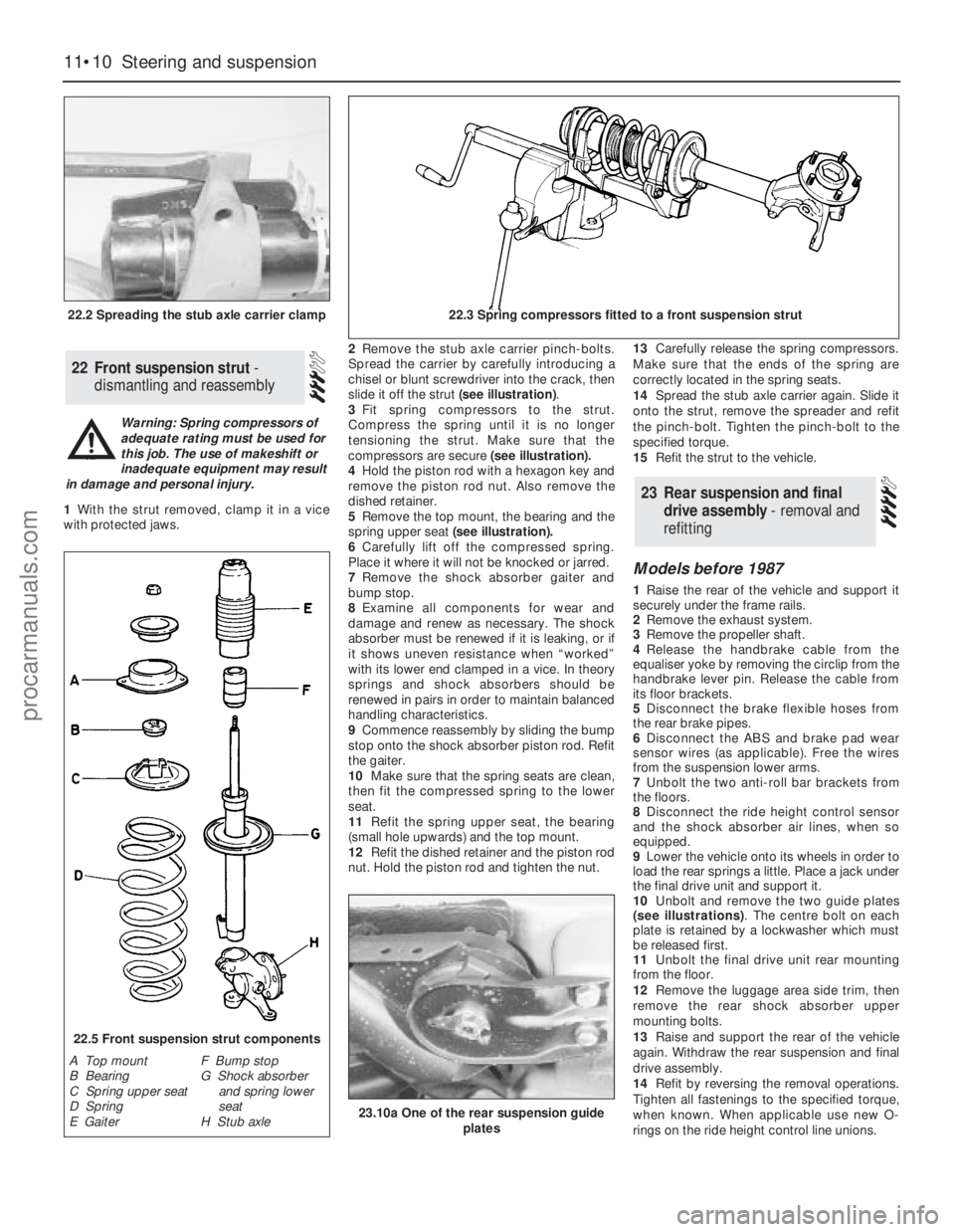
Spread the carrier by carefully introducing a
chisel or blunt screwdriver into the crack, then
slide it off the strut (see illustration).
3Fit spring compressors to the strut.
Compress the spring until it is no longer
tensioning the strut. Make sure that the
compressors are secure (see illustration).
4Hold the piston rod with a hexagon key and
remove the piston rod nut. Also remove the
dished retainer.
5Remove the top mount, the bearing and the
spring upper seat(see illustration).
6Carefully lift off the compressed spring.
Place it where it will not be knocked or jarred.
7Remove the shock absorber gaiter and
bump stop.
8Examine all components for wear and
damage and renew as necessary. The shock
absorber must be renewed if it is leaking, or if
it shows uneven resistance when “worked”
with its lower end clamped in a vice. In theory
springs and shock absorbers should be
renewed in pairs in order to maintain balanced
handling characteristics.
9Commence reassembly by sliding the bump
stop onto the shock absorber piston rod. Refit
the gaiter.
10Make sure that the spring seats are clean,
then fit the compressed spring to the lower
seat.
11Refit the spring upper seat, the bearing
(small hole upwards) and the top mount.
12Refit the dished retainer and the piston rod
nut. Hold the piston rod and tighten the nut.13Carefully release the spring compressors.
Make sure that the ends of the spring are
correctly located in the spring seats.
14Spread the stub axle carrier again. Slide it
onto the strut, remove the spreader and refit
the pinch-bolt. Tighten the pinch-bolt to the
specified torque.
15Refit the strut to the vehicle.
Models before 1987
1Raise the rear of the vehicle and support it
securely under the frame rails.
2Remove the exhaust system.
3Remove the propeller shaft.
4Release the handbrake cable from the
equaliser yoke by removing the circlip from the
handbrake lever pin. Release the cable from
its floor brackets.
5Disconnect the brake flexible hoses from
the rear brake pipes.
6Disconnect the ABS and brake pad wear
sensor wires (as applicable). Free the wires
from the suspension lower arms.
7Unbolt the two anti-roll bar brackets from
the floors.
8Disconnect the ride height control sensor
and the shock absorber air lines, when so
equipped.
9Lower the vehicle onto its wheels in order to
load the rear springs a little. Place a jack under
the final drive unit and support it.
10Unbolt and remove the two guide plates
(see illustrations). The centre bolt on each
plate is retained by a lockwasher which must
be released first.
11Unbolt the final drive unit rear mounting
from the floor.
12Remove the luggage area side trim, then
remove the rear shock absorber upper
mounting bolts.
13Raise and support the rear of the vehicle
again. Withdraw the rear suspension and final
drive assembly.
14Refit by reversing the removal operations.
Tighten all fastenings to the specified torque,
when known. When applicable use new O-
rings on the ride height control line unions.
23Rear suspension and final
drive assembly - removal and
refitting
22Front suspension strut -
dismantling and reassembly
11•10Steering and suspension
22.2 Spreading the stub axle carrier clamp22.3 Spring compressors fitted to a front suspension strut
22.5 Front suspension strut components
A Top mount
B Bearing
C Spring upper seat
D Spring
E GaiterF Bump stop
G Shock absorber
and spring lower
seat
H Stub axle
Warning: Spring compressors of
adequate rating must be used for
this job. The use of makeshift or
inadequate equipment may result
in damage and personal injury.
23.10a One of the rear suspension guide
plates
procarmanuals.com