1985 FORD GRANADA glove box
[x] Cancel search: glove boxPage 91 of 255
panel. Disconnect the wiring connectors from
the heated window switches and fuel
computer (where fitted) and remove the panel
from the car.
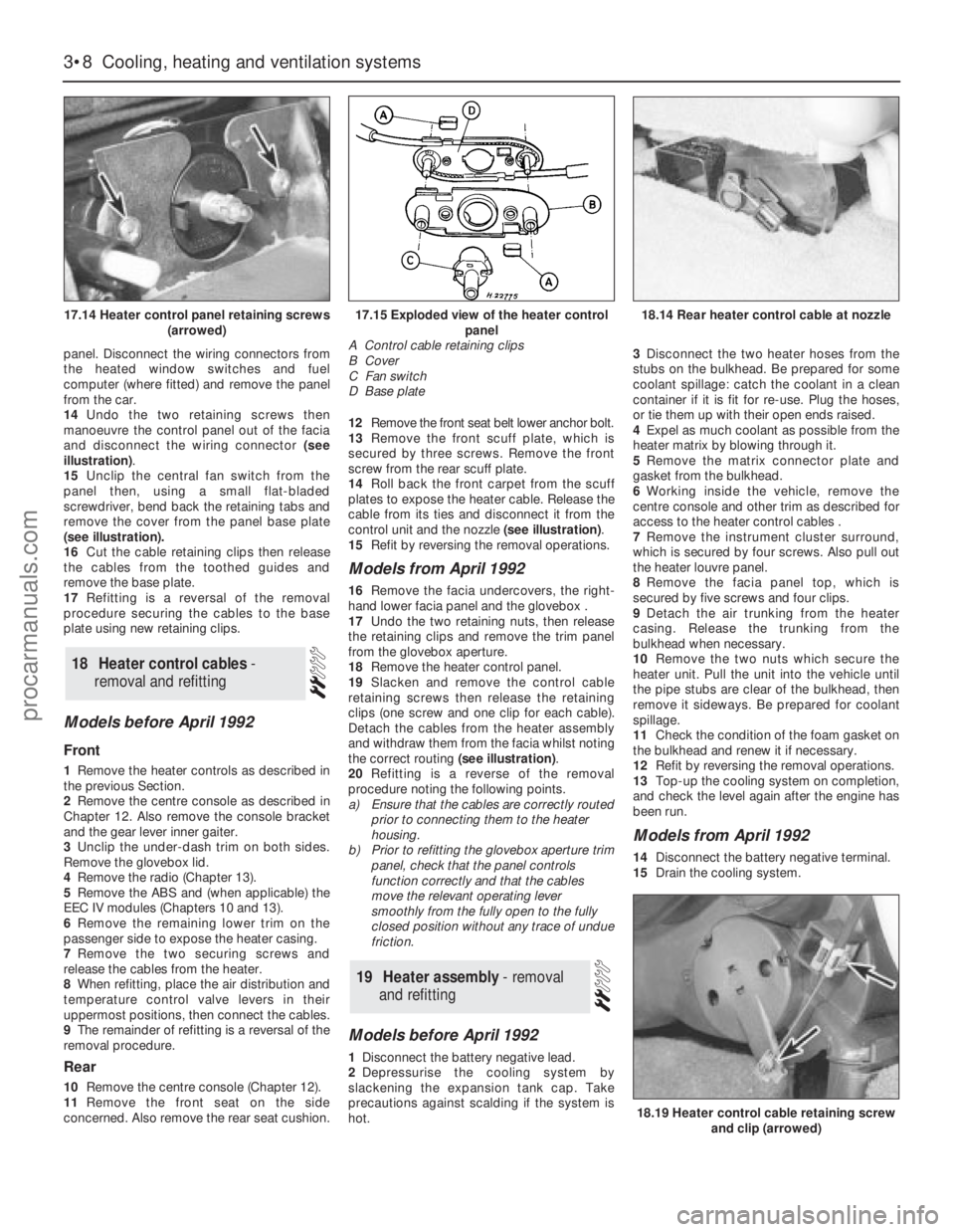
14Undo the two retaining screws then
manoeuvre the control panel out of the facia
and disconnect the wiring connector (see
illustration).
15Unclip the central fan switch from the
panel then, using a small flat-bladed
screwdriver, bend back the retaining tabs and
remove the cover from the panel base plate
(see illustration).
16Cut the cable retaining clips then release
the cables from the toothed guides and
remove the base plate.
17Refitting is a reversal of the removal
procedure securing the cables to the base
plate using new retaining clips.
Models before April 1992
Front
1Remove the heater controls as described in
the previous Section.
2Remove the centre console as described in
Chapter 12. Also remove the console bracket
and the gear lever inner gaiter.
3Unclip the under-dash trim on both sides.
Remove the glovebox lid.
4Remove the radio (Chapter 13).
5Remove the ABS and (when applicable) the
EEC IV modules (Chapters 10 and 13).
6Remove the remaining lower trim on the
passenger side to expose the heater casing.
7Remove the two securing screws and
release the cables from the heater.
8When refitting, place the air distribution and
temperature control valve levers in their
uppermost positions, then connect the cables.
9The remainder of refitting is a reversal of the
removal procedure.
Rear
10Remove the centre console (Chapter 12).
11Remove the front seat on the side
concerned. Also remove the rear seat cushion. 12Remove the front seat belt lower anchor bolt.
13Remove the front scuff plate, which is
secured by three screws. Remove the front
screw from the rear scuff plate.
14Roll back the front carpet from the scuff
plates to expose the heater cable. Release the
cable from its ties and disconnect it from the
control unit and the nozzle (see illustration).
15Refit by reversing the removal operations.
Models from April 1992
16Remove the facia undercovers, the right-
hand lower facia panel and the glovebox .
17Undo the two retaining nuts, then release
the retaining clips and remove the trim panel
from the glovebox aperture.
18Remove the heater control panel.
19Slacken and remove the control cable
retaining screws then release the retaining
clips (one screw and one clip for each cable).
Detach the cables from the heater assembly
and withdraw them from the facia whilst noting
the correct routing (see illustration).
20Refitting is a reverse of the removal
procedure noting the following points.
a)Ensure that the cables are correctly routed
prior to connecting them to the heater
housing.
b)Prior to refitting the glovebox aperture trim
panel, check that the panel controls
function correctly and that the cables
move the relevant operating lever
smoothly from the fully open to the fully
closed position without any trace of undue
friction.
Models before April 1992
1Disconnect the battery negative lead.
2Depressurise the cooling system by
slackening the expansion tank cap. Take
precautions against scalding if the system is
hot.3Disconnect the two heater hoses from the
stubs on the bulkhead. Be prepared for some
coolant spillage: catch the coolant in a clean
container if it is fit for re-use. Plug the hoses,
or tie them up with their open ends raised.
4Expel as much coolant as possible from the
heater matrix by blowing through it.
5Remove the matrix connector plate and
gasket from the bulkhead.
6Working inside the vehicle, remove the
centre console and other trim as described for
access to the heater control cables .
7Remove the instrument cluster surround,
which is secured by four screws. Also pull out
the heater louvre panel.
8Remove the facia panel top, which is
secured by five screws and four clips.
9Detach the air trunking from the heater
casing. Release the trunking from the
bulkhead when necessary.
10Remove the two nuts which secure the
heater unit. Pull the unit into the vehicle until
the pipe stubs are clear of the bulkhead, then
remove it sideways. Be prepared for coolant
spillage.
11Check the condition of the foam gasket on
the bulkhead and renew it if necessary.
12Refit by reversing the removal operations.
13Top-up the cooling system on completion,
and check the level again after the engine has
been run.
Models from April 1992
14Disconnect the battery negative terminal.
15Drain the cooling system.
19Heater assembly - removal
and refitting
18Heater control cables -
removal and refitting
3•8Cooling, heating and ventilation systems
17.14 Heater control panel retaining screws
(arrowed)
18.19 Heater control cable retaining screw
and clip (arrowed)
17.15 Exploded view of the heater control
panel
A Control cable retaining clips
B Cover
C Fan switch
D Base plate18.14 Rear heater control cable at nozzle
procarmanuals.com
Page 126 of 255
into position or the wiring pins will be
damaged.
25Refit the module retaining bolts and
tighten them securely.
26Rotate the distributor until the marks made
on removal are aligned then securely tighten
the clamp bolt.
27Reconnect the distributor wiring
connector and the battery negative terminal.
28Run the engine to normal operating
temperature and check the ignition timing.
All engines except DOHC fuel-
injection
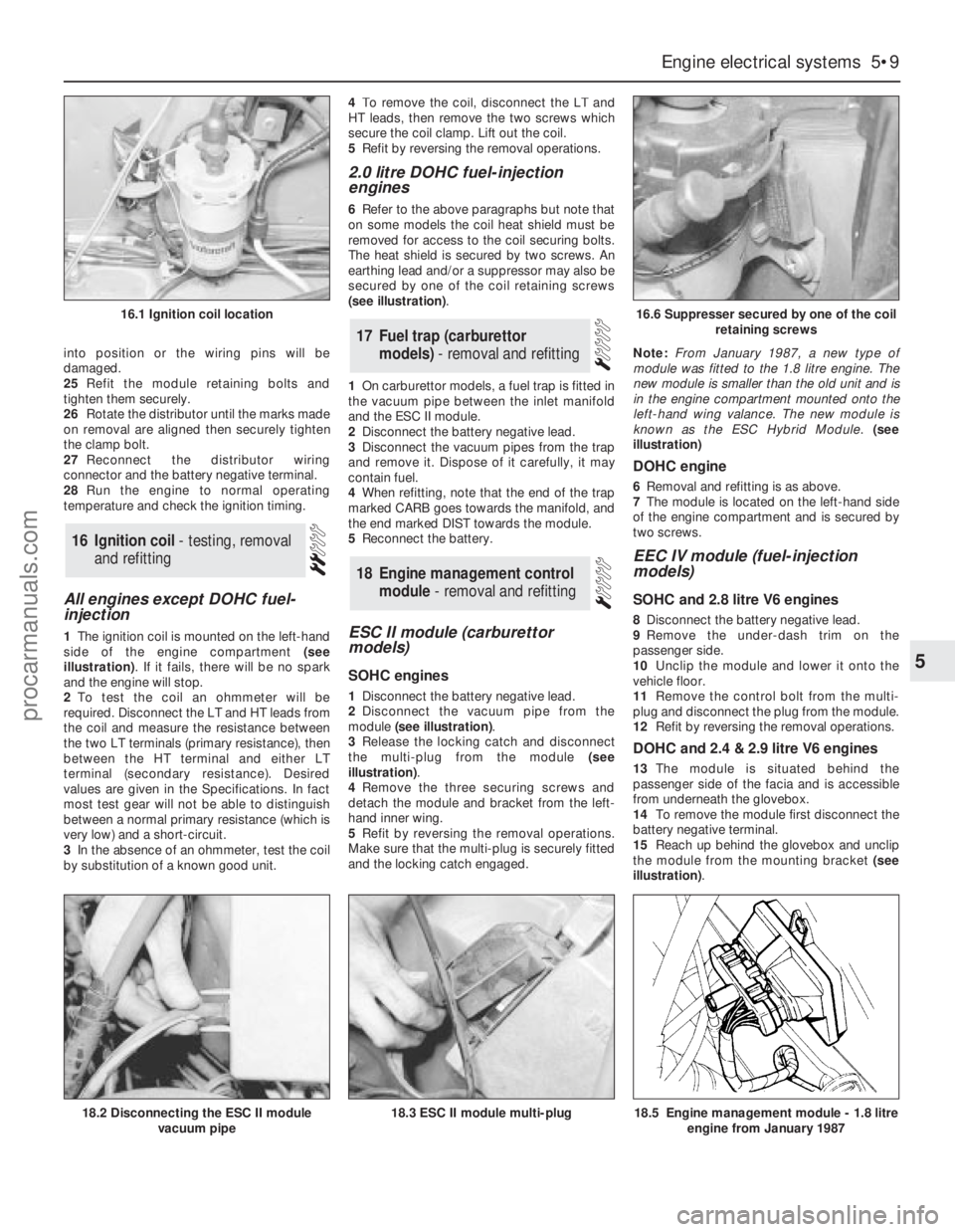
1The ignition coil is mounted on the left-hand
side of the engine compartment (see
illustration). If it fails, there will be no spark
and the engine will stop.
2To test the coil an ohmmeter will be
required. Disconnect the LT and HT leads from
the coil and measure the resistance between
the two LT terminals (primary resistance), then
between the HT terminal and either LT
terminal (secondary resistance). Desired
values are given in the Specifications. In fact
most test gear will not be able to distinguish
between a normal primary resistance (which is
very low) and a short-circuit.
3In the absence of an ohmmeter, test the coil
by substitution of a known good unit.4To remove the coil, disconnect the LT and
HT leads, then remove the two screws which
secure the coil clamp. Lift out the coil.
5Refit by reversing the removal operations.
2.0 litre DOHC fuel-injection
engines
6Refer to the above paragraphs but note that
on some models the coil heat shield must be
removed for access to the coil securing bolts.
The heat shield is secured by two screws. An
earthing lead and/or a suppressor may also be
secured by one of the coil retaining screws
(see illustration).
1On carburettor models, a fuel trap is fitted in
the vacuum pipe between the inlet manifold
and the ESC II module.
2Disconnect the battery negative lead.
3Disconnect the vacuum pipes from the trap
and remove it. Dispose of it carefully, it may
contain fuel.
4When refitting, note that the end of the trap
marked CARB goes towards the manifold, and
the end marked DIST towards the module.
5Reconnect the battery.
ESC II module (carburettor
models)
SOHC engines
1Disconnect the battery negative lead.
2Disconnect the vacuum pipe from the
module (see illustration).
3Release the locking catch and disconnect
the multi-plug from the module (see
illustration).
4Remove the three securing screws and
detach the module and bracket from the left-
hand inner wing.
5Refit by reversing the removal operations.
Make sure that the multi-plug is securely fitted
and the locking catch engaged.Note: From January 1987, a new type of
module was fitted to the 1.8 litre engine. The
new module is smaller than the old unit and is
in the engine compartment mounted onto the
left-hand wing valance. The new module is
known as the ESC Hybrid Module.(see
illustration)
DOHC engine
6Removal and refitting is as above.
7The module is located on the left-hand side
of the engine compartment and is secured by
two screws.
EEC IV module (fuel-injection
models)
SOHC and 2.8 litre V6 engines
8Disconnect the battery negative lead.
9Remove the under-dash trim on the
passenger side.
10Unclip the module and lower it onto the
vehicle floor.
11Remove the control bolt from the multi-
plug and disconnect the plug from the module.
12Refit by reversing the removal operations.
DOHC and 2.4 & 2.9 litre V6 engines
13The module is situated behind the
passenger side of the facia and is accessible
from underneath the glovebox.
14To remove the module first disconnect the
battery negative terminal.
15Reach up behind the glovebox and unclip
the module from the mounting bracket (see
illustration).
18Engine management control
module - removal and refitting
17Fuel trap (carburettor
models) - removal and refitting
16Ignition coil - testing, removal
and refitting
Engine electrical systems 5•9
5
16.1 Ignition coil location16.6 Suppresser secured by one of the coil
retaining screws
18.2 Disconnecting the ESC II module
vacuum pipe18.5 Engine management module - 1.8 litre
engine from January 198718.3 ESC II module multi-plug
procarmanuals.com
Page 127 of 255
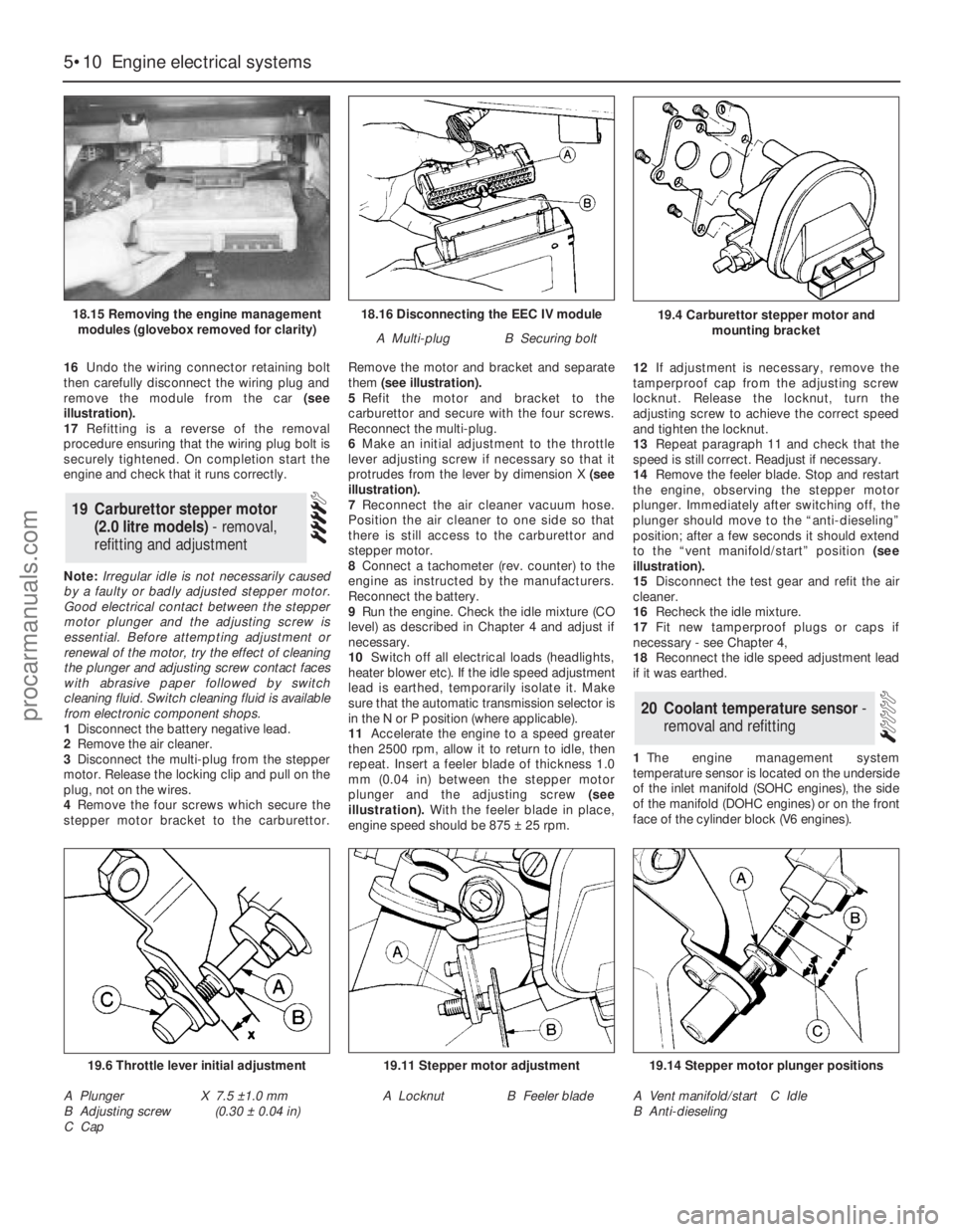
16Undo the wiring connector retaining bolt
then carefully disconnect the wiring plug and
remove the module from the car (see
illustration).
17Refitting is a reverse of the removal
procedure ensuring that the wiring plug bolt is
securely tightened. On completion start the
engine and check that it runs correctly.
Note: Irregular idle is not necessarily caused
by a faulty or badly adjusted stepper motor.
Good electrical contact between the stepper
motor plunger and the adjusting screw is
essential. Before attempting adjustment or
renewal of the motor, try the effect of cleaning
the plunger and adjusting screw contact faces
with abrasive paper followed by switch
cleaning fluid. Switch cleaning fluid is available
from electronic component shops.
1Disconnect the battery negative lead.
2Remove the air cleaner.
3Disconnect the multi-plug from the stepper
motor. Release the locking clip and pull on the
plug, not on the wires.
4Remove the four screws which secure the
stepper motor bracket to the carburettor.Remove the motor and bracket and separate
them (see illustration).
5Refit the motor and bracket to the
carburettor and secure with the four screws.
Reconnect the multi-plug.
6Make an initial adjustment to the throttle
lever adjusting screw if necessary so that it
protrudes from the lever by dimension X (see
illustration).
7Reconnect the air cleaner vacuum hose.
Position the air cleaner to one side so that
there is still access to the carburettor and
stepper motor.
8Connect a tachometer (rev. counter) to the
engine as instructed by the manufacturers.
Reconnect the battery.
9Run the engine. Check the idle mixture (CO
level) as described in Chapter 4 and adjust if
necessary.
10Switch off all electrical loads (headlights,
heater blower etc). If the idle speed adjustment
lead is earthed, temporarily isolate it. Make
sure that the automatic transmission selector is
in the N or P position (where applicable).
11Accelerate the engine to a speed greater
then 2500 rpm, allow it to return to idle, then
repeat. Insert a feeler blade of thickness 1.0
mm (0.04 in) between the stepper motor
plunger and the adjusting screw(see
illustration).With the feeler blade in place,
engine speed should be 875 ±25 rpm. 12If adjustment is necessary, remove the
tamperproof cap from the adjusting screw
locknut. Release the locknut, turn the
adjusting screw to achieve the correct speed
and tighten the locknut.
13Repeat paragraph 11 and check that the
speed is still correct. Readjust if necessary.
14Remove the feeler blade. Stop and restart
the engine, observing the stepper motor
plunger. Immediately after switching off, the
plunger should move to the “anti-dieseling”
position; after a few seconds it should extend
to the “vent manifold/start” position (see
illustration).
15Disconnect the test gear and refit the air
cleaner.
16Recheck the idle mixture.
17Fit new tamperproof plugs or caps if
necessary - see Chapter 4,
18Reconnect the idle speed adjustment lead
if it was earthed.
1The engine management system
temperature sensor is located on the underside
of the inlet manifold (SOHC engines), the side
of the manifold (DOHC engines) or on the front
face of the cylinder block (V6 engines).
20Coolant temperature sensor -
removal and refitting
19Carburettor stepper motor
(2.0 litre models) - removal,
refitting and adjustment
5•10Engine electrical systems
18.16 Disconnecting the EEC IV module
A Multi-plugB Securing bolt
19.6 Throttle lever initial adjustment
A Plunger
B Adjusting screw
C CapX 7.5 ±1.0 mm
(0.30 ±0.04 in)
19.11 Stepper motor adjustment
A LocknutB Feeler blade
19.14 Stepper motor plunger positions
A Vent manifold/start
B Anti-dieselingC Idle
19.4 Carburettor stepper motor and
mounting bracket18.15 Removing the engine management
modules (glovebox removed for clarity)
procarmanuals.com
Page 142 of 255
3If the servo unit still fails to operate
satisfactorily the fault lies within the unit itself.
Repairs to the unit are not possible.
4Remove the master cylinder (Section 27).
5Disconnect the vacuum hose from the servo
unit taking care not to displace the rubber
sealing grommet. Disconnect the wiring plug
from the Pedal Travel Sensor (PTS) which is
situated on the front of the servo.
6Working from inside the vehicle, remove the
servo pushrod retaining clip from the brake
pedal. If necessary, to improve access to the
brake pedal remove the right-hand lower facia
panel .
7Slacken and remove the four nuts securing
the servo unit to the bulkhead, then return to
the engine compartment and remove the
servo unit from the vehicle. Remove the
gasket from the rear of the unit and discard it.
8Note that the vacuum servo unit is a sealed
assembly with no spare parts available
separately. Therefore if it is faulty it must be
renewed as a unit. Inspect the vacuum servo
vacuum hose sealing grommet for damage or
deterioration and renew if necessary.
9Remove all traces of dirt from the servo unit
and bulkhead mating surfaces and fit a new
gasket onto the rear of the servo.
10Manoeuvre the servo unit into position,
ensuring that the servo unit pushrod is
correctly located with the hole in the pedal.
Refit the servo unit retaining nuts and tighten
them to the specified torque setting. Secure
the pushrod in position with the retaining clip
11Carefully refit the vacuum hose to the servo
unit taking great care not to damage or displace
the sealing grommet. Reconnect the wiring
connector to the Pedal Travel Sensor (PTS).
12Refit the master cylinder as described
above. On completion start the engine and
check the operation of the servo unit.
1Disconnect the vacuum hose from the servo
unit taking care not to displace the rubber
sealing grommet.
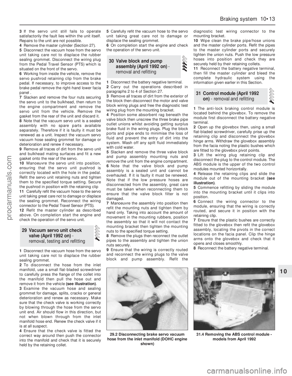
2To disconnect the hose from the inlet
manifold, use a small flat-bladed screwdriver
to carefully press the flange of the collet into
the manifold then pull the hose out and
remove it from the vehicle (see illustration).
3Examine the vacuum hose and sealing
grommet for damage, splits, cracks or general
deterioration and renew as necessary. Make
sure that the check valve is working correctly
by blowing through the hose from the servo
unit end. Air should flow in this direction, but
not when blown through from the inlet
manifold hose end. Renew the check valve if it
is at all suspect.
4Ensure that the check valve is fitted the
correct way around then push the connector
into the manifold and check that it is securely
held by the retaining collet.5Carefully refit the vacuum hose to the servo
unit taking great care not to damage or
displace the sealing grommet.
6On completion start the engine and check
the operation of the servo unit.
1Disconnect the battery negative terminal.
2Carry out the operations described in
paragraphs 2 to 4 of Section 27.
3Remove all traces of dirt from the exterior of
the block then disconnect the motor and valve
block wiring plugs and free the diagnostic test
wiring plug from the mounting bracket.
4Position some absorbent rag beneath the
valve block then unscrew the three brake pipe
outlet unions whilst avoiding getting surplus
brake fluid in the wiring plugs. Plug the block
ports and pipe ends to minimise the loss of
fluid and prevent the entry of dirt into the
system. Wash off any spilt fluid immediately
with cold water.
5Slacken and remove the three valve block
and pump assembly mounting nuts and
remove the unit from the engine compartment.
6Note that the valve block and pump
assembly is a sealed unit and cannot be
overhauled. If it is faulty it must be renewed.
Note that if the low pressure hoses are
disconnected from the assembly, great care
must be taken when reconnecting them to
ensure that the valve block filter is not
damaged.
7Manoeuvre the assembly into position then
refit the mounting nuts and tighten them by
hand only. Taking into account the amount of
movement in the mounting rubbers, position
the assembly so that it will not contact the
mounting bracket then tighten the mounting
nuts to the specified torque setting.
8Remove the plugs then reconnect the outlet
pipes to the assembly and tighten the union
nuts securely.
9Ensure that the wiring is correctly routed
and reconnect the wiring plugs to the valve
block and pump assembly. Refit thediagnostic test wiring connector to the
mounting bracket.
10Wipe clean the brake pipe/hose unions
and the master cylinder ports. Refit the pipes
to the master cylinder ports and securely
tighten the union nuts. Push the low pressure
hoses into position and check they are
securely held by their retaining collets.
11Reconnect the battery negative terminal,
then fill the master cylinder and bleed the
complete hydraulic system using the
information given earlier in this Section.
1The anti-lock braking control module is
located behind the glovebox. To remove the
module first disconnect the battery negative
terminal.
2Open up the glovebox then, using a small
flat-bladed screwdriver, carefully prise up the
retaining clip and disconnect the glovebox
hinge arms. Withdraw the glovebox assembly
from the facia noting the plastic bushes which
are fitted to the glovebox pivot points.
3Lift the wiring plug retaining clip and
disconnect the plug to the control module. The
ABS module is the upper of the two control
modules mounted horizontally.
4Release the retaining clips and slide the
module out of the mounting bracket (see
illustration).
5Commence refitting by sliding the module
into the mounting bracket until it clips into
position.
6Connect the wiring connector to the
module, ensuring that the wiring is correctly
routed, and secure it in position with the
retaining clip.
7Ensure that the plastic bushes are correctly
fitted to the glovebox then refit the glovebox
assembly, locating the pivots in the correct
locations on the facia panel. Clip the hinge
arms onto the glovebox and check that it
opens and closes smoothly.
8Reconnect the battery negative terminal.
31Control module (April 1992
on) - removal and refitting
30Valve block and pump
assembly (April 1992 on) -
removal and refitting
29 Vacuum servo unit check
valve (April 1992 on) -
removal, testing and refitting
Braking system 10•13
10
29.2 Disconnecting brake servo vacuum
hose from the inlet manifold (DOHC engine
shown)31.4 Removing the ABS control module -
models from April 1992
procarmanuals.com
Page 155 of 255
7Unbolt the guide plate from the body on the
side concerned.
8Carefully lower the jack until the spring is no
longer under tension. Remove the spring and
the rubber buffer.
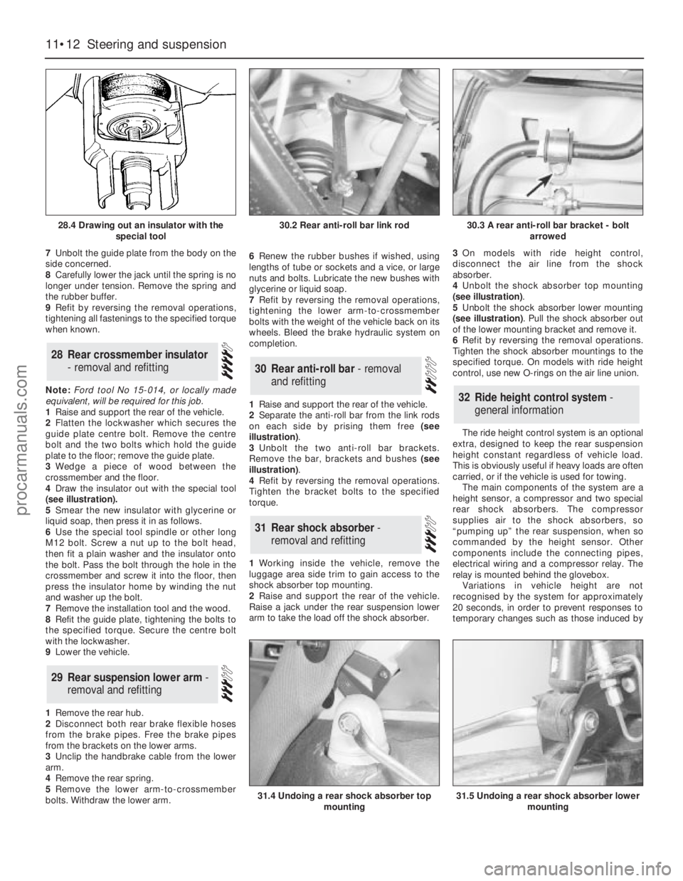
9Refit by reversing the removal operations,
tightening all fastenings to the specified torque
when known.
Note: Ford tool No 15-014, or locally made
equivalent, will be required for this job.
1Raise and support the rear of the vehicle.
2Flatten the lockwasher which secures the
guide plate centre bolt. Remove the centre
bolt and the two bolts which hold the guide
plate to the floor; remove the guide plate.
3Wedge a piece of wood between the
crossmember and the floor.
4Draw the insulator out with the special tool
(see illustration).
5Smear the new insulator with glycerine or
liquid soap, then press it in as follows.
6Use the special tool spindle or other long
M12 bolt. Screw a nut up to the bolt head,
then fit a plain washer and the insulator onto
the bolt. Pass the bolt through the hole in the
crossmember and screw it into the floor, then
press the insulator home by winding the nut
and washer up the bolt.
7Remove the installation tool and the wood.
8Refit the guide plate, tightening the bolts to
the specified torque. Secure the centre bolt
with the lockwasher.
9Lower the vehicle.
1Remove the rear hub.
2Disconnect both rear brake flexible hoses
from the brake pipes. Free the brake pipes
from the brackets on the lower arms.
3Unclip the handbrake cable from the lower
arm.
4Remove the rear spring.
5Remove the lower arm-to-crossmember
bolts. Withdraw the lower arm.6Renew the rubber bushes if wished, using
lengths of tube or sockets and a vice, or large
nuts and bolts. Lubricate the new bushes with
glycerine or liquid soap.
7Refit by reversing the removal operations,
tightening the lower arm-to-crossmember
bolts with the weight of the vehicle back on its
wheels. Bleed the brake hydraulic system on
completion.
1Raise and support the rear of the vehicle.
2Separate the anti-roll bar from the link rods
on each side by prising them free (see
illustration).
3Unbolt the two anti-roll bar brackets.
Remove the bar, brackets and bushes (see
illustration).
4Refit by reversing the removal operations.
Tighten the bracket bolts to the specified
torque.
1Working inside the vehicle, remove the
luggage area side trim to gain access to the
shock absorber top mounting.
2Raise and support the rear of the vehicle.
Raise a jack under the rear suspension lower
arm to take the load off the shock absorber.3On models with ride height control,
disconnect the air line from the shock
absorber.
4Unbolt the shock absorber top mounting
(see illustration).
5Unbolt the shock absorber lower mounting
(see illustration). Pull the shock absorber out
of the lower mounting bracket and remove it.
6Refit by reversing the removal operations.
Tighten the shock absorber mountings to the
specified torque. On models with ride height
control, use new O-rings on the air line union.
The ride height control system is an optional
extra, designed to keep the rear suspension
height constant regardless of vehicle load.
This is obviously useful if heavy loads are often
carried, or if the vehicle is used for towing.
The main components of the system are a
height sensor, a compressor and two special
rear shock absorbers. The compressor
supplies air to the shock absorbers, so
“pumping up” the rear suspension, when so
commanded by the height sensor. Other
components include the connecting pipes,
electrical wiring and a compressor relay. The
relay is mounted behind the glovebox.
Variations in vehicle height are not
recognised by the system for approximately
20 seconds, in order to prevent responses to
temporary changes such as those induced by
32Ride height control system -
general information
31Rear shock absorber -
removal and refitting
30Rear anti-roll bar - removal
and refitting
29Rear suspension lower arm -
removal and refitting
28Rear crossmember insulator
- removal and refitting
11•12Steering and suspension
28.4 Drawing out an insulator with the
special tool
31.4 Undoing a rear shock absorber top
mounting31.5 Undoing a rear shock absorber lower
mounting
30.2 Rear anti-roll bar link rod30.3 A rear anti-roll bar bracket - bolt
arrowed
procarmanuals.com
Page 170 of 255
6Disconnect the glovebox arms and hinges.
Withdraw the hinge pins and remove the lid.
7Slide the auxiliary fuse panel off its
mounting and remove the glovebox light
(when fitted).
8Remove the ABS and ESC/EEC modules
(Chapter 13). Remove the two nuts and
washers from inside the glovebox.
9Remove the radio, stowage box or graphic
equaliser, ashtray, cigarette lighter panel and
(when applicable) the gear lever gaiter.
10Remove the centre console, disconnecting
switches, rear heater controls etc as
necessary.
11Remove the six screws which secure the
passenger’s side lower panel. Remove the
panel. 12Refit by reversing the removal operations,
transferring the brackets, captive nuts or other
fittings to any new panels being fitted.
Models from April 1992
13Disconnect the battery negative terminal.
14Remove the centre console.
15Remove the radio, amplifier unit and
(where necessary) the CD player.
16Remove the instrument cluster.
17Remove the steering wheel and then the
steering column direction indicator/headlight
flasher switch and windscreen wipe/wash
switch.
18Pull off the three knobs from the heater
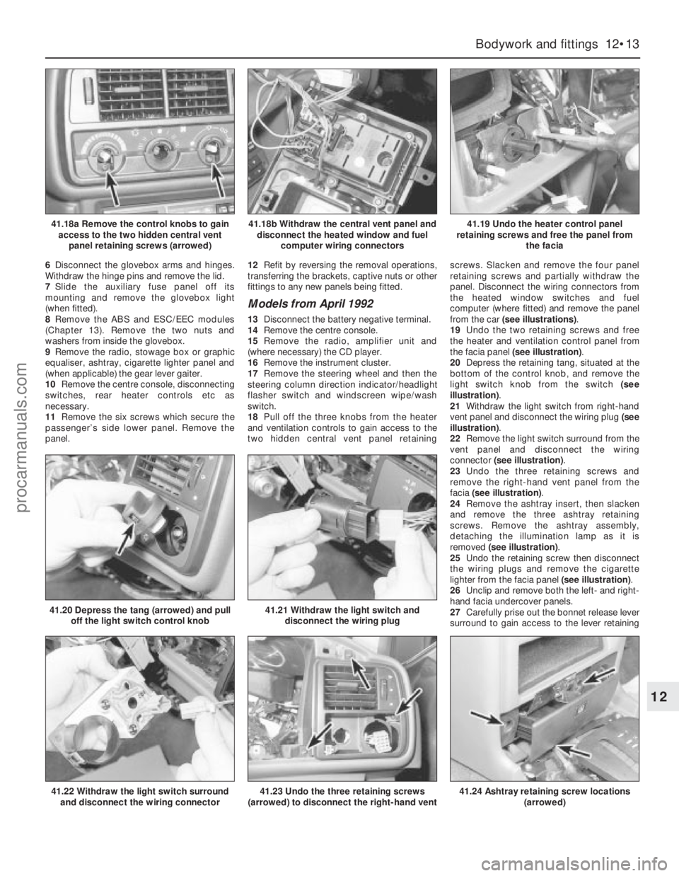
and ventilation controls to gain access to the
two hidden central vent panel retainingscrews. Slacken and remove the four panel
retaining screws and partially withdraw the
panel. Disconnect the wiring connectors from
the heated window switches and fuel
computer (where fitted) and remove the panel
from the car (see illustrations).
19Undo the two retaining screws and free
the heater and ventilation control panel from
the facia panel (see illustration).
20Depress the retaining tang, situated at the
bottom of the control knob, and remove the
light switch knob from the switch (see
illustration).
21Withdraw the light switch from right-hand
vent panel and disconnect the wiring plug (see
illustration).
22Remove the light switch surround from the
vent panel and disconnect the wiring
connector (see illustration).
23Undo the three retaining screws and
remove the right-hand vent panel from the
facia (see illustration).
24Remove the ashtray insert, then slacken
and remove the three ashtray retaining
screws. Remove the ashtray assembly,
detaching the illumination lamp as it is
removed (see illustration).
25Undo the retaining screw then disconnect
the wiring plugs and remove the cigarette
lighter from the facia panel (see illustration).
26Unclip and remove both the left- and right-
hand facia undercover panels.
27Carefully prise out the bonnet release lever
surround to gain access to the lever retaining
Bodywork and fittings 12•13
12
41.18a Remove the control knobs to gain
access to the two hidden central vent
panel retaining screws (arrowed)41.18b Withdraw the central vent panel and
disconnect the heated window and fuel
computer wiring connectors41.19 Undo the heater control panel
retaining screws and free the panel from
the facia
41.22 Withdraw the light switch surround
and disconnect the wiring connector
41.20 Depress the tang (arrowed) and pull
off the light switch control knob41.21 Withdraw the light switch and
disconnect the wiring plug
41.23 Undo the three retaining screws
(arrowed) to disconnect the right-hand vent41.24 Ashtray retaining screw locations
(arrowed)
procarmanuals.com
Page 171 of 255
12•14Bodywork and fittings
41.25 Withdraw the cigarette lighter and
disconnect the wiring plugs
41.30 Removing the passenger side lower
kick panel
41.29a Lift the glovebox hinge retaining
clips and disconnect the hinge arms41.29b Withdraw the glovebox noting the
plastic bushes (arrowed) which are fitted to
the pivot bolts
41.29c Withdraw the glovebox illumination
light and disconnect the wiring connector
41.28 Undo the five right-hand lower facia
panel retaining screws (arrowed)
41.31a A-pillar trim panel retaining clip . . .
41.31b . . . and lower locating tab (viewed
through windscreen)
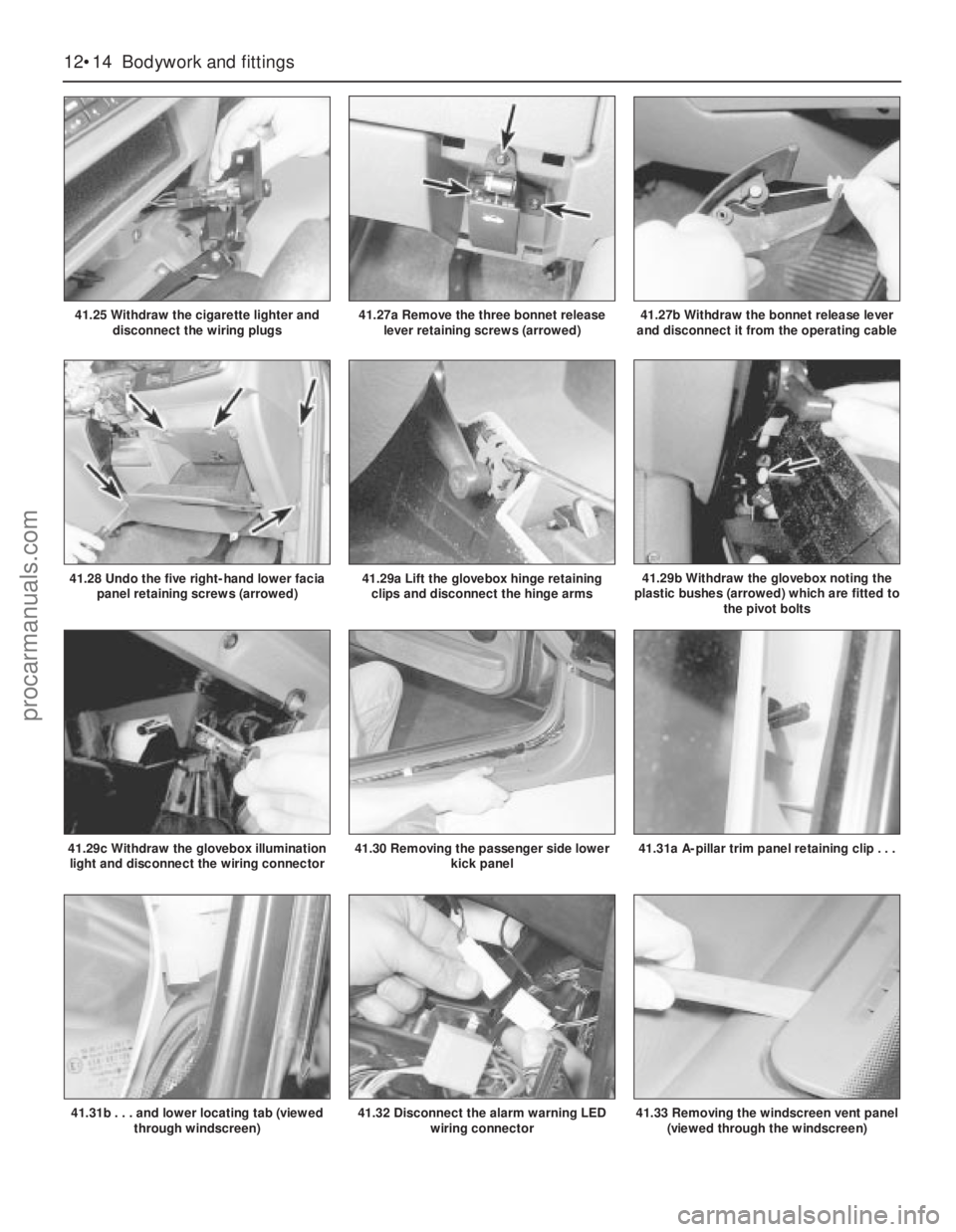
41.27a Remove the three bonnet release
lever retaining screws (arrowed)41.27b Withdraw the bonnet release lever
and disconnect it from the operating cable
41.32 Disconnect the alarm warning LED
wiring connector41.33 Removing the windscreen vent panel
(viewed through the windscreen)
procarmanuals.com
Page 172 of 255
screws. Undo the three screws then withdraw
the lever. Remove the cable retaining clip and
detach the operating lever from the cable (see
illustrations).
28Slacken and remove the five right-hand
lower facia panel retaining screws and remove
the panel from the vehicle (see illustration).
29Open up the glovebox then, using a small
flat-bladed screwdriver, carefully prise up the
retaining clip and disconnect the glovebox
hinge arms. Withdraw the glovebox assembly
from the facia noting the plastic bushes which
are fitted to the glovebox pivot points.
Withdraw the glovebox illumination light,
disconnect the wiring connector and remove it
from the facia (see illustrations).
30Slacken and remove the three screws
securing the passenger side lower kick panel
in position and remove the panel (see
illustration).
31Carefully prise the upper end of the left-
hand A-pillar trim out of position until all the
retaining clips are released. Lift the panel up to
disengage the lower tab from the pillar and
remove the trim panel (see illustrations).
Repeat the procedure for the right-hand panel.
32Disconnect the alarm warning LED wiring
connector which is accessed via the
instrument cluster aperture (see illustration).
33Carefully prise the windscreen vent panel
out from the top of the facia to gain access to
the upper facia retaining screws (see
illustration).
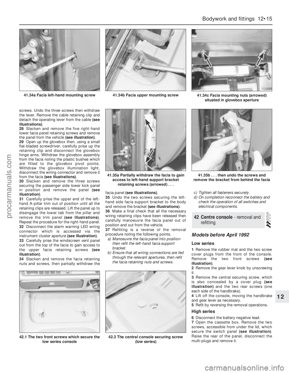
34Slacken and remove the facia retaining
nuts and screws, then partially withdraw thefacia panel (see illustrations).
35Undo the two screws securing the left-
hand side facia support bracket to the body
and remove the bracket (see illustrations).
36Make a final check that all the necessary
wiring retaining clips have been released then
carefully manoeuvre the facia panel out of
position and out from the vehicle.
37Refitting is a reverse of the removal
procedure noting the following points.
a)Manoeuvre the facia panel into position
then refit the left-hand facia support
bracket.
b)Ensure that all wiring connections are fed
through the relevant apertures, then refit
the facia retaining nuts and screws.c)Tighten all fasteners securely.
d)On completion reconnect the battery and
check the operation of all switches and
electrical components.
Models before April 1992
Low series
1Remove the rubber mat and the two screw
cover plugs from the front of the console.
Remove the two front screws (see
illustration).
2Remove the gear lever knob by unscrewing
it.
3Remove the central securing screw, which
is also concealed by a cover plug (see
illustration)and the two rear screws (one
each side of the handbrake).
4Lift off the console, moving the handbrake
and gear lever as necessary.
5Refit by reversing the removal operations.
High series
6Disconnect the battery negative lead.
7Open the cassette box. Remove the two
screws, accessible from under the lid, which
secure the switch panel (see illustration).
Raise the rear of the panel, disconnect the
multi-plugs and remove it.
42Centre console - removal and
refitting
Bodywork and fittings 12•15
12
41.34c Facia mounting nuts (arrowed)
situated in glovebox aperture41.34b Facia upper mounting screw41.34a Facia left-hand mounting screw
41.35a Partially withdraw the facia to gain
access to left-hand support bracket
retaining screws (arrowed) . . .41.35b . . . then undo the screws and
remove the bracket from behind the facia
42.1 The two front screws which secure the
low series console42.3 The central console securing screw
(low series)
procarmanuals.com