1985 FORD GRANADA clutch
[x] Cancel search: clutchPage 12 of 255
engine valve clearances must be correct. The
ignition system must also be in good
condition.
3Mixture adjustment is not usual on a routine
basis. If the CO level is incorrect, proceed as
follows.
4Connect the exhaust gas analyser as
instructed by the manufacturers.
5Raise the engine speed to 3000 rpm
approximately and hold it at this speed for
30 seconds, then allow it to idle. Repeat this
procedure every 60 seconds until adjustment
is complete.6Read the CO level when it has stabilised
after the 3000 rpm burst. The desired level is
given in the Specifications of Chapter 4
(Pierburg 2V carburettor).
7If the idle mixture needs adjustment, turn
the mixture adjusting screw. The screw may
be covered by a tamperproof plug.
8Recheck the idle speed after adjusting the
mixture.
9Stop the engine and disconnect the test
gear. 10Fit a new tamperproof plug to the mixture
adjusting screw if required.
2.0 litre SOHC engine
11If mixture adjustment is required, proceed
as described for the 1.8 litre engine above.
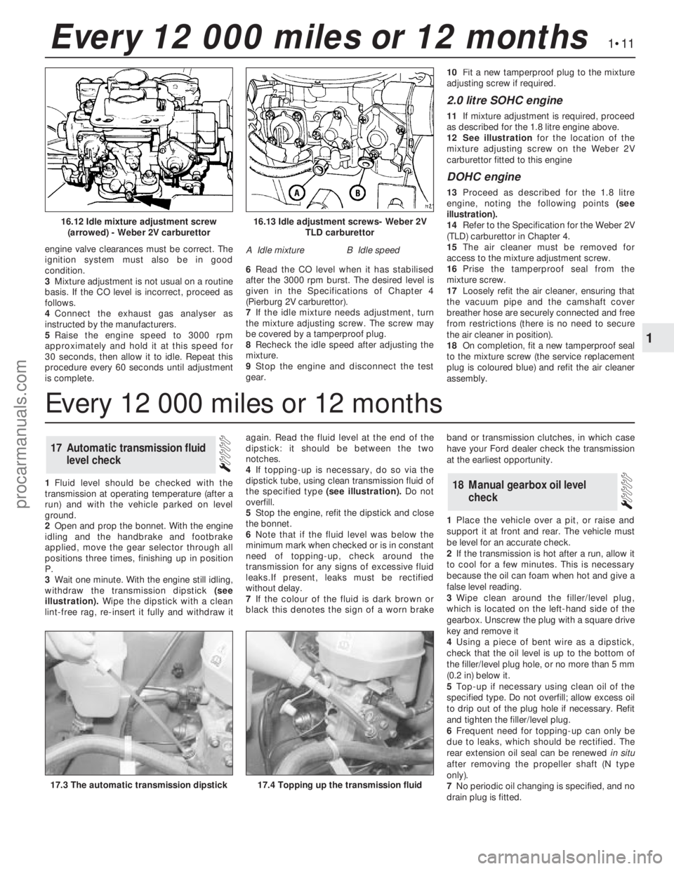
12See illustrationfor the location of the
mixture adjusting screw on the Weber 2V
carburettor fitted to this engine
DOHC engine
13Proceed as described for the 1.8 litre
engine, noting the following points (see
illustration).
14Refer to the Specification for the Weber 2V
(TLD) carburettor in Chapter 4.
15The air cleaner must be removed for
access to the mixture adjustment screw.
16Prise the tamperproof seal from the
mixture screw.
17Loosely refit the air cleaner, ensuring that
the vacuum pipe and the camshaft cover
breather hose are securely connected and free
from restrictions (there is no need to secure
the air cleaner in position).
18On completion, fit a new tamperproof seal
to the mixture screw (the service replacement
plug is coloured blue) and refit the air cleaner
assembly.
1Fluid level should be checked with the
transmission at operating temperature (after a
run) and with the vehicle parked on level
ground.
2Open and prop the bonnet. With the engine
idling and the handbrake and footbrake
applied, move the gear selector through all
positions three times, finishing up in position
P.
3Wait one minute. With the engine still idling,
withdraw the transmission dipstick (see
illustration).Wipe the dipstick with a clean
lint-free rag, re-insert it fully and withdraw itagain. Read the fluid level at the end of the
dipstick: it should be between the two
notches.
4If topping-up is necessary, do so via the
dipstick tube, using clean transmission fluid of
the specified type (see illustration).Do not
overfill.
5Stop the engine, refit the dipstick and close
the bonnet.
6Note that if the fluid level was below the
minimum mark when checked or is in constant
need oftopping-up, check around the
transmission for any signs of excessive fluid
leaks.If present, leaks must be rectified
without delay.
7If the colour of the fluid is dark brown or
black this denotes the sign of a worn brakeband or transmission clutches, in which case
have your Ford dealer check the transmission
at the earliest opportunity.
1Place the vehicle over a pit, or raise and
support it at front and rear. The vehicle must
be level for an accurate check.
2If the transmission is hot after a run, allow it
to cool for a few minutes. This is necessary
because the oil can foam when hot and give a
false level reading.
3Wipe clean around the filler/level plug,
which is located on the left-hand side of the
gearbox. Unscrew the plug with a square drive
key and remove it
4Using a piece of bent wire as a dipstick,
check that the oil level is up to the bottom of
the filler/level plug hole, or no more than 5 mm
(0.2 in) below it.
5Top-up if necessary using clean oil of the
specified type. Do not overfill; allow excess oil
to drip out of the plug hole if necessary. Refit
and tighten the filler/level plug.
6Frequent need for topping-up can only be
due to leaks, which should be rectified. The
rear extension oil seal can be renewedin situ
after removing the propeller shaft (N type
only).
7No periodic oil changing is specified, and no
drain plug is fitted.
18Manual gearbox oil level
check
17Automatic transmission fluid
level check
1•11
1
Every 12 000 miles or 12 months
16.13 Idle adjustment screws- Weber 2V
TLD carburettor
A Idle mixtureB Idle speed
16.12 Idle mixture adjustment screw
(arrowed) - Weber 2V carburettor
17.4 Topping up the transmission fluid17.3 The automatic transmission dipstick
Every 12 000 miles or 12 months
procarmanuals.com
Page 17 of 255
Instruments and electrical
equipment
1Check the operation of all instruments and
electrical equipment.
2Make sure that all instruments read
correctly, and switch on all electrical
equipment in turn to check that it functions
properly.
Steering and suspension
3Check for any abnormalities in the steering,
suspension, handling or road “feel”.
4Drive the vehicle, and check that there are
no unusual vibrations or noises.
5Check that the steering feels positive, with
no excessive “sloppiness”, or roughness, and
check for any suspension noises when
cornering, or when driving over bumps.
Drivetrain
6Check the performance of the engine,
clutch, transmission and driveshafts.
7Listen for any unusual noises from the
engine, clutch and transmission.
8Make sure that the engine runs smoothly
when idling, and that there is no hesitation
when accelerating.
9Where applicable, check that the clutch
action is smooth and progressive, that the
drive is taken up smoothly, and that the pedal
travel is not excessive. Also listen for any
noises when the clutch pedal is depressed.
10Check that all gears can be engaged
smoothly, without noise, and that the gear
lever action is not abnormally vague or
“notchy”.
Check the operation and
performance of the braking system
11Make sure that the vehicle does not pull to
one side when braking, and that the wheels do
not lock prematurely when braking hard.
12Check that there is no vibration through
the steering when braking.
13Check that the handbrake operates
correctly, without excessive movement of the
lever, and that it holds the vehicle stationary
on a slope.
14Test the operation of the brake servo unit
as follows. With the engine off, depress the
footbrake four or five times to exhaust the
vacuum. Start the engine, holding the brake
pedal depressed. As the engine starts, there
should be a noticeable “give” in the brake
pedal as vacuum builds up. Allow the engine
to run for at least two minutes, and then
switch it off. If the brake pedal is depressed
now, it should be possible to detect a hiss
from the servo as the pedal is depressed. After
about four or five applications, no further
hissing should be heard, and the pedal should
feel considerably firmer.1The power steering fluid dipstick is
incorporated in the reservoir filler cap. The
reservoir is mounted on the pump. Observe
scrupulous cleanliness when checking the
level or topping-up.
2The system should be at operating
temperature and the engine switched off.
Wipe clean around the reservoir filler cap.
Unscrew the cap, withdraw the dipstick and
wipe it with a clean lint-free rag. Reinsert the
dipstick, screw the cap home, then unscrew it
again and read the level on the dipstick. It
should be up to the MAX or upper HOT mark
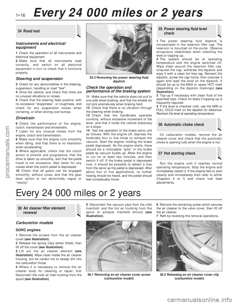
(depending on the dipstick markings) (see
illustration).
3Top-up if necessary with clean fluid of the
specified type. Check for leaks if topping-up is
frequently required.
4If the level is checked cold, use the MIN or
FULL COLD mark on the dipstick for reference.
Recheck the level at operating temperature.
On carburettor models, remove the air
cleaner cover and check that the automatic
choke is opening fully when the engine is hot.
Run the engine until it reaches normal
operating temperature. Stop the engine and
immediately restart it. If the engine fails to start
cleanly and immediately then refer to either
Chapters 4 or 5 and check fuel feed
adjustments.
37Hot starting check
36Automatic choke check
35Power steering fluid level
check34Road test
Carburettor models
SOHC engines
1Remove the screws from the air cleaner
cover(see illustration).
2Release the spring clips (when fitted), then
lift off the cover (see illustration).
3Lift out the air cleaner element(see
illustration). Wipe clean inside the air cleaner
housing, but be careful not to sweep dirt into
the carburettor throat.
4Where it is necessary to remove the air
cleaner body for cleaning or repair, first
disconnect the cold air inlet trunking from the
spout (see illustration). 5Disconnect the vacuum pipe from the inlet
manifold, and the hot air trunking from the
spout or exhaust manifold shroud(see
illustration). 6Remove the remaining screw which secures
the air cleaner to the valve cover, then lift off
the air cleaner.
7Refit by reversing the removal operations.
38Air cleaner filter element
renewal
1•16Every 24 000 miles or 2 years
35.2 Removing the power steering fluid
dipstick
38.2 Releasing an air cleaner cover clip
(carburettor model)38.1 Removing an air cleaner cover screw
(carburettor model)
Every 24 000 miles or 2 years
procarmanuals.com
Page 28 of 255
The cylinder head is of crossflow design
with the inlet manifold mounted on the left-
hand side and the exhaust manifold mounted
on the right-hand side.
Lubrication is by means of a bi-rotor pump
which draws oil through a strainer located
inside the sump, and forces it through a full-
flow filter into the engine oil galleries where it
is distributed to the crankshaft, camshaft and
auxiliary shaft. The big-end bearings are
supplied with oil via internal drillings in the
crankshaft.The undersides of the pistons are
supplied with oil from drillings in the big-ends.
The distributor shaft is intermittently supplied
with oil from the drilled auxiliary shaft. The
camshaft and cam followers are supplied with
oil via a drilled spray tube from the centre
camshaft bearing.
A semi-closed crankcase ventilation system
is employed whereby piston blow-by gases
are drawn into the inlet manifold via an oil
separator and on carburettor models a control
valve.
The following operations can be carried out
without removing the engine, although the
work may be easier and quicker with the
engine removed:
a)Removal and refitting of the cylinder head
b)Removal and refitting of the camshaft
(after removing the cylinder head)
c)Removal and refitting of the timing belt
and sprockets
d)Removal and refitting of the sump and oil
pump
e)Removal and refitting of the pistons,
connecting rods and big-end bearings
f)Renewal of the engine mountings
g)Renewal of the crankshaft oil seals
h)Removal and refitting of the auxiliary shaft
j)Removal and refitting of the flywheel
The engine must be removed from the
vehicle for the following operations:
a)Renewal of the crankshaft main bearings
b)Removal and refitting of the crankshaft
The engine may be lifted out either on its
own or together with the gearbox. Unless work
is also necessary on the gearbox it is
recommended that the engine is removed on
its own. Where automatic transmission is
fitted, the engine should be removed on its
own owing to the additional weight. If the
engine and gearbox are removed together,
they will have to be tilted at a very steep angle;
make sure that the range of the lifting tackle is
adequate.1Disconnect the battery negative lead.
2Remove the bonnet.
3On carburettor models, remove the air
cleaner. On fuel-injection models, remove the
air cleaner cover, vane airflow meter and air
inlet trunking.
4If a splash guard is fitted, remove it.
5Release the securing clips and bolts and
remove the upper half of the fan shroud. On
carburettor models remove the lower half of
the shroud too.
6Drain the cooling system.
7Disconnect the radiator top and bottom
hoses from the thermostat housing and water
pump. Disconnect the top hose spur from the
expansion tank and unclip it.
8Disconnect the heater hoses from the water
pump and from the inlet manifold or automatic
choke housing. Unclip the hoses.
9On models with power steering, remove the
steering pump.
10Disconnect the vacuum pipe(s) from the
inlet manifold, labelling them if there is any
possibility of confusion.
11Disconnect the following wiring, as
applicable:
a)Alternator
b)Temperature gauge sender
c)Engine management temperature sensor
d)Distributor
e)Oil pressure switch
f)Automatic choke and thermo-switch
g)Carburettor stepper motor
h)Fuel-injection system sub-harness
j)Inlet manifold heater
12Disconnect the HT lead from the coil.
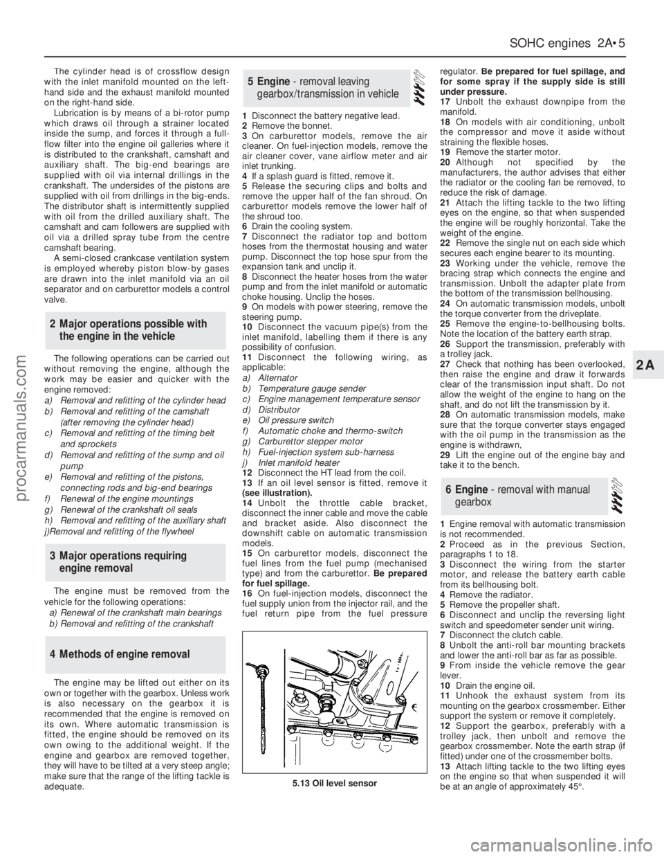
13If an oil level sensor is fitted, remove it
(see illustration).
14Unbolt the throttle cable bracket,
disconnect the inner cable and move the cable
and bracket aside. Also disconnect the
downshift cable on automatic transmission
models.
15On carburettor models, disconnect the
fuel lines from the fuel pump (mechanised
type) and from the carburettor. Be prepared
for fuel spillage.
16On fuel-injection models, disconnect the
fuel supply union from the injector rail, and the
fuel return pipe from the fuel pressureregulator. Be prepared for fuel spillage, and
for some spray if the supply side is still
under pressure.
17Unbolt the exhaust downpipe from the
manifold.
18On models with air conditioning, unbolt
the compressor and move it aside without
straining the flexible hoses.
19Remove the starter motor.
20Although not specified by the
manufacturers, the author advises that either
the radiator or the cooling fan be removed, to
reduce the risk of damage.
21Attach the lifting tackle to the two lifting
eyes on the engine, so that when suspended
the engine will be roughly horizontal. Take the
weight of the engine.
22Remove the single nut on each side which
secures each engine bearer to its mounting.
23Working under the vehicle, remove the
bracing strap which connects the engine and
transmission. Unbolt the adapter plate from
the bottom of the transmission bellhousing.
24On automatic transmission models, unbolt
the torque converter from the driveplate.
25Remove the engine-to-bellhousing bolts.
Note the location of the battery earth strap.
26Support the transmission, preferably with
a trolley jack.
27Check that nothing has been overlooked,
then raise the engine and draw it forwards
clear of the transmission input shaft. Do not
allow the weight of the engine to hang on the
shaft, and do not lift the transmission by it.
28On automatic transmission models, make
sure that the torque converter stays engaged
with the oil pump in the transmission as the
engine is withdrawn,
29Lift the engine out of the engine bay and
take it to the bench.
1Engine removal with automatic transmission
is not recommended.
2Proceed as in the previous Section,
paragraphs 1 to 18.
3Disconnect the wiring from the starter
motor, and release the battery earth cable
from its bellhousing bolt.
4Remove the radiator.
5Remove the propeller shaft.
6Disconnect and unclip the reversing light
switch and speedometer sender unit wiring.
7Disconnect the clutch cable.
8Unbolt the anti-roll bar mounting brackets
and lower the anti-roll bar as far as possible.
9From inside the vehicle remove the gear
lever.
10Drain the engine oil.
11Unhook the exhaust system from its
mounting on the gearbox crossmember. Either
support the system or remove it completely.
12Support the gearbox, preferably with a
trolley jack, then unbolt and remove the
gearbox crossmember. Note the earth strap (if
fitted) under one of the crossmember bolts.
13Attach lifting tackle to the two lifting eyes
on the engine so that when suspended it will
be at an angle of approximately 45°.
6Engine - removal with manual
gearbox
5Engine - removal leaving
gearbox/transmission in vehicle
4Methods of engine removal
3Major operations requiring
engine removal
2Major operations possible with
the engine in the vehicle
SOHCengines 2A•5
2A
5.13 Oil level sensor
procarmanuals.com
Page 29 of 255
14Take the weight of the engine and remove
the two engine bearer-to-mounting nuts.
15Lift the engine/transmission, at the same
time lowering the trolley jack. Draw the unit
forwards and lift it out of the engine bay.
16Temporarily refit the anti-roll bar if the
vehicle is to be moved.
1With the engine and gearbox on the bench,
remove the starter motor.
2Remove the bolt from the engine adapter plate.
3Remove the bracing strap and the
remaining engine-to-bellhousing bolts.
4With the aid of an assistant draw the
gearbox off the engine. Do not allow the weight
of the gearbox to hang on the input shaft.
1It is best to mount the engine on a
dismantling stand, but if this is not available,
stand the engine on a strong bench at a
comfortable working height. Failing this, it will
have to be stripped down on the floor.
2Cleanliness is most important, and if the
engine is dirty, it should be cleaned with
paraffin while keeping it in an upright position.
3Avoid working with the engine on a concrete
floor, as grit can be a real source of trouble.
4As parts are removed, clean them in paraffin.
However, do not immerse parts with internal
oilways in paraffin as it is difficult to remove,
usually requiring a high pressure hose.
5It is advisable to have suitable containers to
hold small items according to their use, as this
will help when reassembling the engine and
also prevent possible losses.
6Always obtain complete sets of gaskets
when the engine is being dismantled, but
retain the old gaskets with a view of using
them as a pattern to make a replacement if a
new one is not available.7When possible, refit nuts, bolts and washers
in their location after being removed, as this
helps protect the threads and will also be
helpful when reassembling the engine.
8Retain unserviceable components in order
to compare them with the new parts supplied.
9A Torx key, size T55, will be needed for
dealing with the cylinder head bolts. A 12-
spline key (to fit bolt size M8) will be needed
for the oil pump bolts. Other Torx and 12-
spline bolts may be encountered; sets of the
keys required to deal with them are available
from most motor accessory shops and tool
factors.
10Another tool which is useful, though by no
means essential, is a valve spring compressor
of the type which hooks under the camshaft
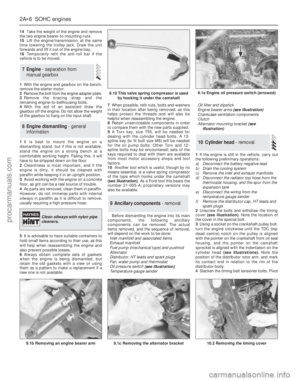
(see illustration). As a Ford tool this bears the
number 21-005-A; proprietary versions may
also be available.
Before dismantling the engine into its main
components, the following ancillary
components can be removed. The actual
items removed, and the sequence of removal,
will depend on the work to be done:
Inlet manifold and associated items
Exhaust manifold
Fuel pump (mechanical type) and pushrod
Alternator
Distributor, HT leads and spark plugs
Fan, water pump and thermostat
Oil pressure switch
(see illustration)
Temperature gauge senderOil filter and dipstick
Engine bearer arms (see illustration)
Crankcase ventilation components
Clutch
Alternator mounting bracket (see
illustration)
1If the engine is still in the vehicle, carry out
the following preliminary operations:
a)Disconnect the battery negative lead
b)Drain the cooling system
c)Remove the inlet and exhaust manifolds
d)Disconnect the radiator top hose from the
thermostat housing, and the spur from the
expansion tank
e)Disconnect the wiring from the
temperature gauge sender
f)Remove the distributor cap, HT leads and
spark plugs
2Unscrew the bolts and withdraw the timing
cover (see illustration). Note the location of
the cover in the special bolt.
3Using a socket on the crankshaft pulley bolt.
turn the engine clockwise until the TDC (top
dead centre) notch on the pulley is aligned
with the pointer on the crankshaft front oil seal
housing, and the pointer on the camshaft
sprocket is aligned with the indentation on the
cylinder head (see illustrations).Note the
position of the distributor rotor arm, and mark
its contact end in relation to the rim of the
distributor body.
4Slacken the timing belt tensioner bolts. Pivot
10Cylinder head - removal
9Ancillary components - removal
8Engine dismantling - general
information
7Engine - separation from
manual gearbox
2A•6SOHCengines
9.1a Engine oil pressure switch (arrowed)
9.1b Removing an engine bearer arm9.1c Removing the alternator bracket
8.10 This valve spring compressor is used
by hooking it under the camshaft
Clean oilways with nylon pipe
cleaners.
10.2 Removing the timing cover
procarmanuals.com
Page 32 of 255
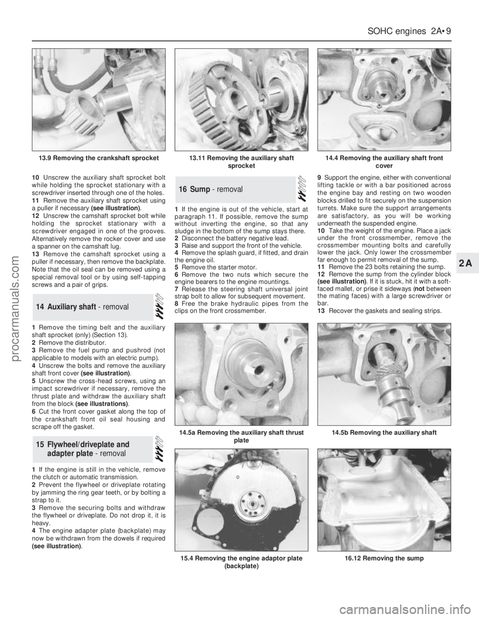
10Unscrew the auxiliary shaft sprocket bolt
while holding the sprocket stationary with a
screwdriver inserted through one of the holes.
11Remove the auxiliary shaft sprocket using
a puller if necessary (see illustration).
12Unscrew the camshaft sprocket bolt while
holding the sprocket stationary with a
screwdriver engaged in one of the grooves.
Alternatively remove the rocker cover and use
a spanner on the camshaft lug.
13Remove the camshaft sprocket using a
puller if necessary, then remove the backplate.
Note that the oil seal can be removed using a
special removal tool or by using self-tapping
screws and a pair of grips.
1Remove the timing belt and the auxiliary
shaft sprocket (only) (Section 13).
2Remove the distributor.
3Remove the fuel pump and pushrod (not
applicable to models with an electric pump).
4Unscrew the bolts and remove the auxiliary
shaft front cover (see illustration).
5Unscrew the cross-head screws, using an
impact screwdriver if necessary, remove the
thrust plate and withdraw the auxiliary shaft
from the block (see illustrations).
6Cut the front cover gasket along the top of
the crankshaft front oil seal housing and
scrape off the gasket.
1If the engine is still in the vehicle, remove
the clutch or automatic transmission.
2Prevent the flywheel or driveplate rotating
by jamming the ring gear teeth, or by bolting a
strap to it.
3Remove the securing bolts and withdraw
the flywheel or driveplate. Do not drop it, it is
heavy.
4The engine adapter plate (backplate) may
now be withdrawn from the dowels if required
(see illustration).1If the engine is out of the vehicle, start at
paragraph 11. If possible, remove the sump
without inverting the engine, so that any
sludge in the bottom of the sump stays there.
2Disconnect the battery negative lead.
3Raise and support the front of the vehicle.
4Remove the splash guard, if fitted, and drain
the engine oil.
5Remove the starter motor.
6Remove the two nuts which secure the
engine bearers to the engine mountings.
7Release the steering shaft universal joint
strap bolt to allow for subsequent movement.
8Free the brake hydraulic pipes from the
clips on the front crossmember.9Support the engine, either with conventional
lifting tackle or with a bar positioned across
the engine bay and resting on two wooden
blocks drilled to fit securely on the suspension
turrets. Make sure the support arrangements
are satisfactory, as you will be working
underneath the suspended engine.
10Take the weight of the engine. Place a jack
under the front crossmember, remove the
crossmember mounting bolts and carefully
lower the jack. Only lower the crossmember
far enough to permit removal of the sump.
11Remove the 23 bolts retaining the sump.
12Remove the sump from the cylinder block
(see illustration). If it is stuck, hit it with a soft-
faced mallet, or prise it sideways (notbetween
the mating faces) with a large screwdriver or
bar.
13Recover the gaskets and sealing strips.
16Sump - removal
15Flywheel/driveplate and
adapter plate - removal
14Auxiliary shaft - removal
SOHCengines 2A•9
2A
13.9 Removing the crankshaft sprocket13.11 Removing the auxiliary shaft
sprocket14.4 Removing the auxiliary shaft front
cover
14.5b Removing the auxiliary shaft14.5a Removing the auxiliary shaft thrust
plate
15.4 Removing the engine adaptor plate
(backplate)16.12 Removing the sump
procarmanuals.com
Page 39 of 255
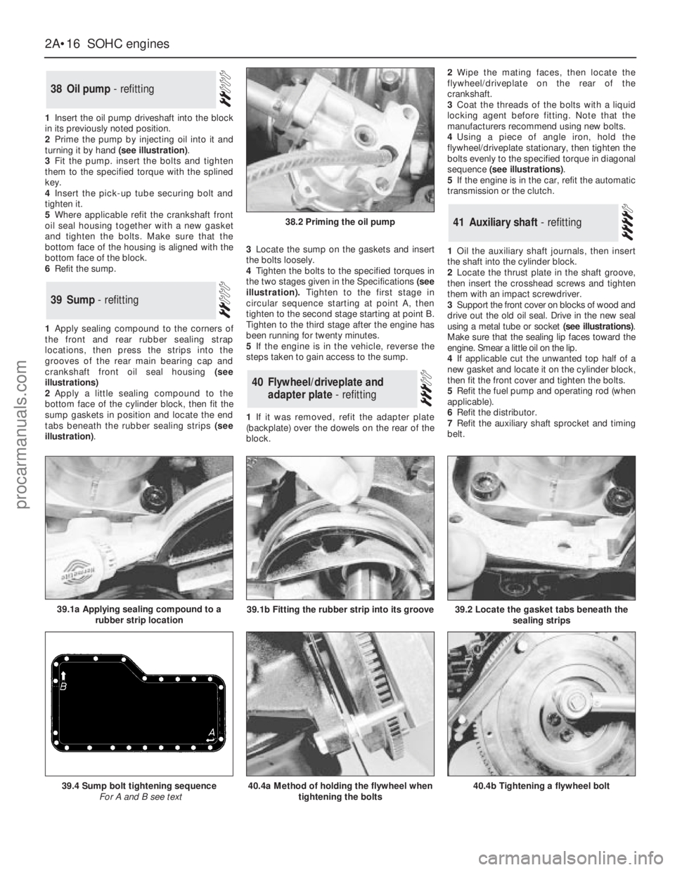
1Insert the oil pump driveshaft into the block
in its previously noted position.
2Prime the pump by injecting oil into it and
turning it by hand (see illustration).
3Fit the pump. insert the bolts and tighten
them to the specified torque with the splined
key.
4Insert the pick-up tube securing bolt and
tighten it.
5Where applicable refit the crankshaft front
oil seal housing together with a new gasket
and tighten the bolts. Make sure that the
bottom face of the housing is aligned with the
bottom face of the block.
6Refit the sump.
1Apply sealing compound to the corners of
the front and rear rubber sealing strap
locations, then press the strips into the
grooves of the rear main bearing cap and
crankshaft front oil seal housing (see
illustrations)
2Apply a little sealing compound to the
bottom face of the cylinder block, then fit the
sump gaskets in position and locate the end
tabs beneath the rubber sealing strips (see
illustration).3Locate the sump on the gaskets and insert
the bolts loosely.
4Tighten the bolts to the specified torques in
the two stages given in the Specifications(see
illustration).Tighten to the first stage in
circular sequence starting at point A, then
tighten to the second stage starting at point B.
Tighten to the third stage after the engine has
been running for twenty minutes.
5If the engine is in the vehicle, reverse the
steps taken to gain access to the sump.
1If it was removed, refit the adapter plate
(backplate) over the dowels on the rear of the
block.2Wipe the mating faces, then locate the
flywheel/driveplate on the rear of the
crankshaft.
3Coat the threads of the bolts with a liquid
locking agent before fitting. Note that the
manufacturers recommend using new bolts.
4Using a piece of angle iron, hold the
flywheel/driveplate stationary, then tighten the
bolts evenly to the specified torque in diagonal
sequence (see illustrations).
5If the engine is in the car, refit the automatic
transmission or the clutch.
1Oil the auxiliary shaft journals, then insert
the shaft into the cylinder block.
2Locate the thrust plate in the shaft groove,
then insert the crosshead screws and tighten
them with an impact screwdriver.
3Support the front cover on blocks of wood and
drive out the old oil seal. Drive in the new seal
using a metal tube or socket (see illustrations).
Make sure that the sealing lip faces toward the
engine. Smear a little oil on the lip.
4If applicable cut the unwanted top half of a
new gasket and locate it on the cylinder block,
then fit the front cover and tighten the bolts.
5Refit the fuel pump and operating rod (when
applicable).
6Refit the distributor.
7Refit the auxiliary shaft sprocket and timing
belt.
41Auxiliary shaft - refitting
40Flywheel/driveplate and
adapter plate - refitting
39Sump - refitting
38Oil pump - refitting
2A•16SOHCengines
38.2 Priming the oil pump
40.4a Method of holding the flywheel when
tightening the bolts39.4 Sump bolt tightening sequence
For A and B see text40.4b Tightening a flywheel bolt
39.2 Locate the gasket tabs beneath the
sealing strips39.1a Applying sealing compound to a
rubber strip location39.1b Fitting the rubber strip into its groove
procarmanuals.com
Page 42 of 255
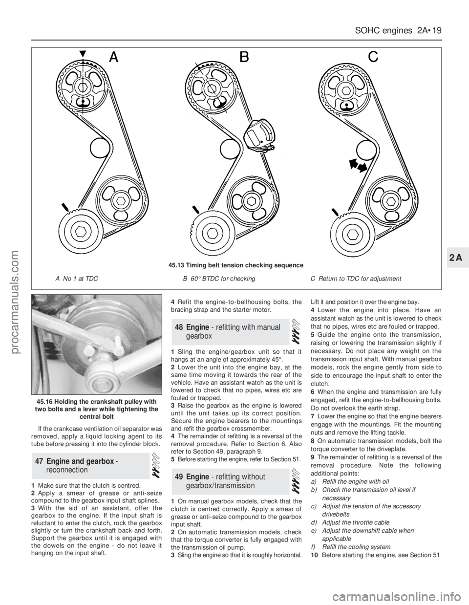
If the crankcase ventilation oil separator was
removed, apply a liquid locking agent to its
tube before pressing it into the cylinder block.
1Make sure that the clutch is centred.
2Apply a smear of grease or anti-seize
compound to the gearbox input shaft splines.
3With the aid of an assistant, offer the
gearbox to the engine. If the input shaft is
reluctant to enter the clutch, rock the gearbox
slightly or turn the crankshaft back and forth.
Support the gearbox until it is engaged with
the dowels on the engine - do not leave it
hanging on the input shaft.4Refit the engine-to-bellhousing bolts, the
bracing strap and the starter motor.
1Sling the engine/gearbox unit so that it
hangs at an angle of approximately 45°.
2Lower the unit into the engine bay, at the
same time moving it towards the rear of the
vehicle. Have an assistant watch as the unit is
lowered to check that no pipes, wires etc are
fouled or trapped.
3Raise the gearbox as the engine is lowered
until the unit takes up its correct position.
Secure the engine bearers to the mountings
and refit the gearbox crossmember.
4The remainder of refitting is a reversal of the
removal procedure. Refer to Section 6. Also
refer to Section 49, paragraph 9.
5Before starting the engine, refer to Section 51.
1On manual gearbox models, check that the
clutch is centred correctly. Apply a smear of
grease or anti-seize compound to the gearbox
input shaft.
2On automatic transmission models, check
that the torque converter is fully engaged with
the transmission oil pump.
3Sling the engine so that it is roughly horizontal.Lift it and position it over the engine bay.
4Lower the engine into place. Have an
assistant watch as the unit is lowered to check
that no pipes, wires etc are fouled or trapped.
5Guide the engine onto the transmission,
raising or lowering the transmission slightly if
necessary. Do not place any weight on the
transmission input shaft. With manual gearbox
models, rock the engine gently from side to
side to encourage the input shaft to enter the
clutch.
6When the engine and transmission are fully
engaged, refit the engine-to-bellhousing bolts.
Do not overlook the earth strap.
7Lower the engine so that the engine bearers
engage with the mountings. Fit the mounting
nuts and remove the lifting tackle.
8On automatic transmission models, bolt the
torque converter to the driveplate.
9The remainder of refitting is a reversal of the
removal procedure. Note the following
additional points:
a)Refill the engine with oil
b)Check the transmission oil level if
necessary
c)Adjust the tension of the accessory
drivebelts
d)Adjust the throttle cable
e)Adjust the downshift cable when
applicable
f)Refill the cooling system
10Before starting the engine, see Section 51
49Engine - refitting without
gearbox/transmission
48Engine - refitting with manual
gearbox
47Engine and gearbox -
reconnection
SOHCengines 2A•19
2A
45.16 Holding the crankshaft pulley with
two bolts and a lever while tightening the
central bolt
45.13 Timing belt tension checking sequence
A No 1 at TDCB 60°BTDC for checkingC Return to TDC for adjustment
procarmanuals.com
Page 47 of 255
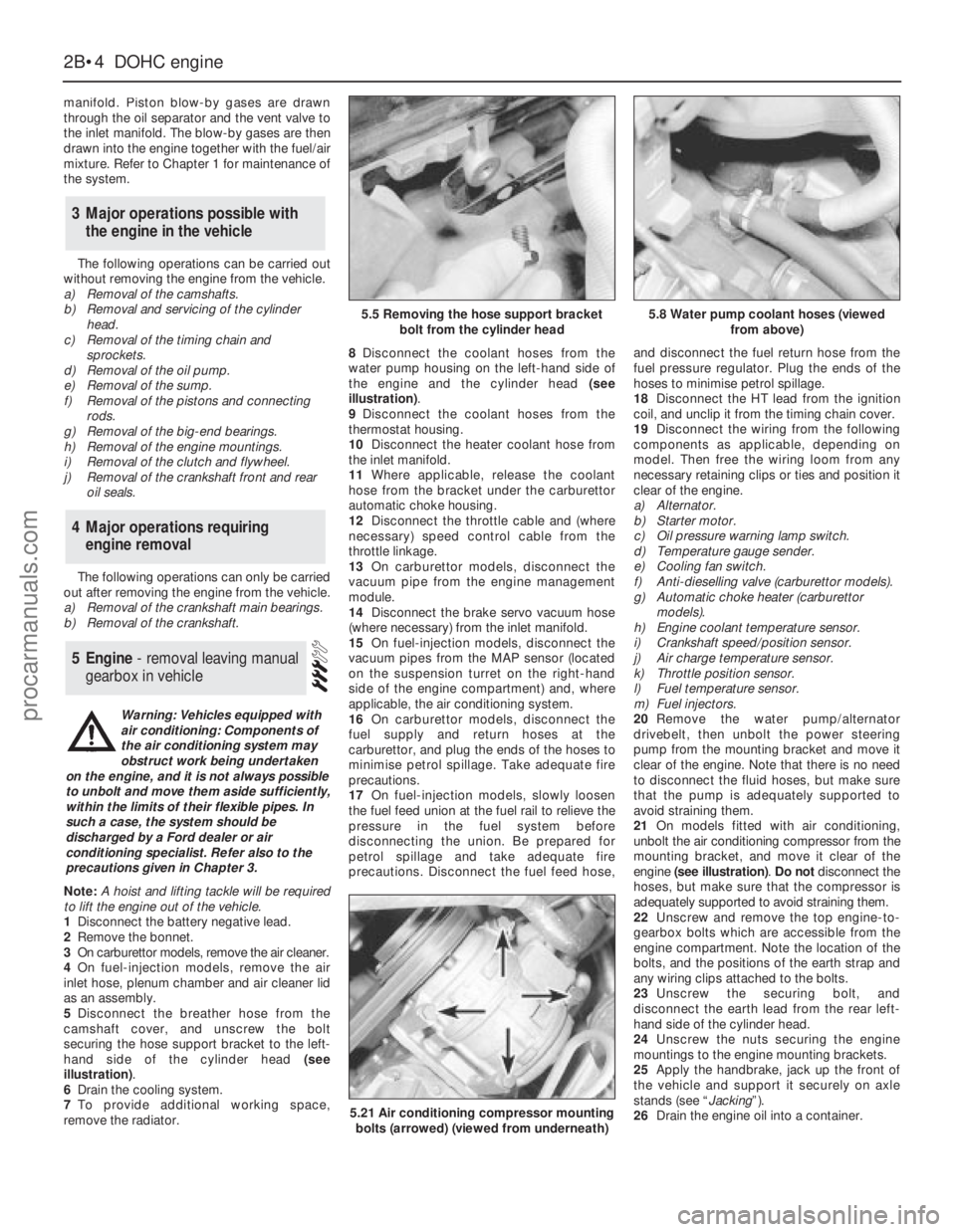
manifold. Piston blow-by gases are drawn
through the oil separator and the vent valve to
the inlet manifold. The blow-by gases are then
drawn into the engine together with the fuel/air
mixture. Refer to Chapter 1 for maintenance of
the system.
The following operations can be carried out
without removing the engine from the vehicle.
a)Removal of the camshafts.
b)Removal and servicing of the cylinder
head.
c)Removal of the timing chain and
sprockets.
d)Removal of the oil pump.
e)Removal of the sump.
f)Removal of the pistons and connecting
rods.
g)Removal of the big-end bearings.
h)Removal of the engine mountings.
i)Removal of the clutch and flywheel.
j)Removal of the crankshaft front and rear
oil seals.
The following operations can only be carried
out after removing the engine from the vehicle.
a)Removal of the crankshaft main bearings.
b)Removal of the crankshaft.
Note: A hoist and lifting tackle will be required
to lift the engine out of the vehicle.
1Disconnect the battery negative lead.
2Remove the bonnet.
3On carburettor models, remove the air cleaner.
4On fuel-injection models, remove the air
inlet hose, plenum chamber and air cleaner lid
as an assembly.
5Disconnect the breather hose from the
camshaft cover, and unscrew the bolt
securing the hose support bracket to the left-
hand side of the cylinder head (see
illustration).
6Drain the cooling system.
7To provide additional working space,
remove the radiator.8Disconnect the coolant hoses from the
water pump housing on the left-hand side of
the engine and the cylinder head (see
illustration).
9Disconnect the coolant hoses from the
thermostat housing.
10Disconnect the heater coolant hose from
the inlet manifold.
11Where applicable, release the coolant
hose from the bracket under the carburettor
automatic choke housing.
12Disconnect the throttle cable and (where
necessary) speed control cable from the
throttle linkage.
13On carburettor models, disconnect the
vacuum pipe from the engine management
module.
14Disconnect the brake servo vacuum hose
(where necessary) from the inlet manifold.
15On fuel-injection models, disconnect the
vacuum pipes from the MAP sensor (located
on the suspension turret on the right-hand
side of the engine compartment) and, where
applicable, the air conditioning system.
16On carburettor models, disconnect the
fuel supply and return hoses at the
carburettor, and plug the ends of the hoses to
minimise petrol spillage. Take adequate fire
precautions.
17On fuel-injection models, slowly loosen
the fuel feed union at the fuel rail to relieve the
pressure in the fuel system before
disconnecting the union. Be prepared for
petrol spillage and take adequate fire
precautions. Disconnect the fuel feed hose,and disconnect the fuel return hose from the
fuel pressure regulator. Plug the ends of the
hoses to minimise petrol spillage.
18Disconnect the HT lead from the ignition
coil, and unclip it from the timing chain cover.
19Disconnect the wiring from the following
components as applicable, depending on
model. Then free the wiring loom from any
necessary retaining clips or ties and position it
clear of the engine.
a)Alternator.
b)Starter motor.
c)Oil pressure warning lamp switch.
d)Temperature gauge sender.
e)Cooling fan switch.
f)Anti-dieselling valve (carburettor models).
g)Automatic choke heater (carburettor
models).
h)Engine coolant temperature sensor.
i)Crankshaft speed/position sensor.
j)Air charge temperature sensor.
k)Throttle position sensor.
l)Fuel temperature sensor.
m)Fuel injectors.
20Remove the water pump/alternator
drivebelt, then unbolt the power steering
pump from the mounting bracket and move it
clear of the engine. Note that there is no need
to disconnect the fluid hoses, but make sure
that the pump is adequately supported to
avoid straining them.
21On models fitted with air conditioning,
unbolt the air conditioning compressor from the
mounting bracket, and move it clear of the
engine (see illustration). Do notdisconnect the
hoses, but make sure that the compressor is
adequately supported to avoid straining them.
22Unscrew and remove the top engine-to-
gearbox bolts which are accessible from the
engine compartment. Note the location of the
bolts, and the positions of the earth strap and
any wiring clips attached to the bolts.
23Unscrew the securing bolt, and
disconnect the earth lead from the rear left-
hand side of the cylinder head.
24Unscrew the nuts securing the engine
mountings to the engine mounting brackets.
25Apply the handbrake, jack up the front of
the vehicle and support it securely on axle
stands (see “Jacking”).
26Drain the engine oil into a container.
5Engine - removal leaving manual
gearbox in vehicle
4Major operations requiring
engine removal
3Major operations possible with
the engine in the vehicle
2B•4DOHCengine
5.5 Removing the hose support bracket
bolt from the cylinder head5.8 Water pump coolant hoses (viewed
from above)
5.21 Air conditioning compressor mounting
bolts (arrowed) (viewed from underneath)
Warning: Vehicles equipped with
air conditioning: Components of
the air conditioning system may
obstruct work being undertaken
on the engine, and it is not always possible
to unbolt and move them aside sufficiently,
within the limits of their flexible pipes. In
such a case, the system should be
discharged by a Ford dealer or air
conditioning specialist. Refer also to the
precautions given in Chapter 3.
procarmanuals.com