1985 FORD GRANADA tow bar
[x] Cancel search: tow barPage 13 of 255

1Work around the vehicle, and lubricate the
hinges and locks with a light machine oil.
2Lightly lubricate the bonnet release
mechanism and exposed sections of inner
cable with a smear of grease.
3Check the security and operation of all
hinges, latches and locks, adjusting them
where required. Where applicable, check the
operation of the central locking system.
4Check the condition and operation of the
tailgate struts, renewing them if either is
leaking or is no longer able to support the
tailgate securely when raised.
SOHC and V6 engines
1The correct functioning of the spark plugs is
vital for the correct running and efficiency of
the engine. It is essential that the plugs fitted
are appropriate for the engine.
2Make sure that the ignition is switched off
before inspecting the HT leads to see if they
carry their cylinder numbers - if not, number
each lead using sticky tape or paint.
3Pull the HT lead connectors off the plugs.
Pull on the connectors, not on the leads.
4Blow away any dirt from around the spark
plug recesses in the cylinder head(s).
5Unscrew and remove the plugs, using a
proprietary plug spanner or a spark plug
socket, extension and ratchet.
6The condition of the plugs will tell much
about the overall condition of the engine. If the
insulator nose of the spark plug is clean and
white, with no deposits, this is indicative of a
weak mixture or too hot a plug (a hot plug
transfers heat away from the electrode slowly,
a cold plug transfers heat away quickly).
7If the tip and insulator nose are covered with
hard black-looking deposits, then this is
indicative that the mixture is too rich. Should
the plug be black and oily, then it is likely that
the engine is fairly worn, as well as the mixture
being too rich.
8If the insulator nose is covered with light tan
to greyish-brown deposits, then the mixture is
correct, and it is likely that the engine is in
good condition.
9Apply a smear of anti-seize compound to
the threads of the new plugs. Make sure that
theinsulators are clean and that the screwed
HT lead adapters are tight. Pay particular
attention to the plug seating surfaces on OHC
engines, since these plugs have no sealing
washers (“taper seat” type) and any dirt will
cause a bad seal.
10Screw each plug into its hole by hand. If a
plug is reluctant to go in, do not force it with a
spanner, but unscrew it and try again. If the
plug is cross-threaded, it is the cylinder head
which will be damaged.11Final tightening of the spark plugs should
ideally be carried out using a torque wrench.
The tightening torques are given in the
Specifications. If a torque wrench is not
available, tighten the plugs beyond the point
where they contact the head as follows:
OHC (taper seat plugs) - One-sixteenth of a
turn maximum
V6 (plugs with washers) - One-quarter of a
turn maximum
12If the taper seat type of plug is
overtightened, the sealing faces will bite
together and removal will be very difficult.
13Refit the HT leads to the plugs, paying
attention to the cylinder numbers. Push each
connector firmly onto its plug.
14Run the engine to verify that the HT leads
have been refitted correctly.
DOHC engines
15Proceed as described above whilst noting
the following points.
a)Remove the air cleaner as described in
Chapter 4.
b)The minimal length of number 3 HT lead
makes removal from the spark plug
difficult. It is advisable to remove this lead
from the distributor prior to removing it
from the spark plug.
c)The spark plugs are deeply recessed in
the cylinder head and it will be necessary
to use a spark plug socket with a long
extension bar. If possible, use a spark plug
socket with a rubber grip inside as this will
hold onto the spark plug once loosened
and will enable the spark plugs to be
withdrawn and refitted more easily.
SOHC and all V6 engines
1All of these engines have one or two
drivebelts which drive the water pump and
alternator from the crankshaft pulley. When
power steering is fitted, the same belts drive
the steering pump. The air conditioning
compressor, when fitted, is driven
independently.
2Periodically inspect the drivebelt(s) for
fraying, cracks, glazing or other damage. Turn
the engine so that the full length of the belt(s)
can be viewed. Renew belts which are in poor
condition. When twin drivebelts are fitted, both
must be renewed together, even if only one is
damaged.
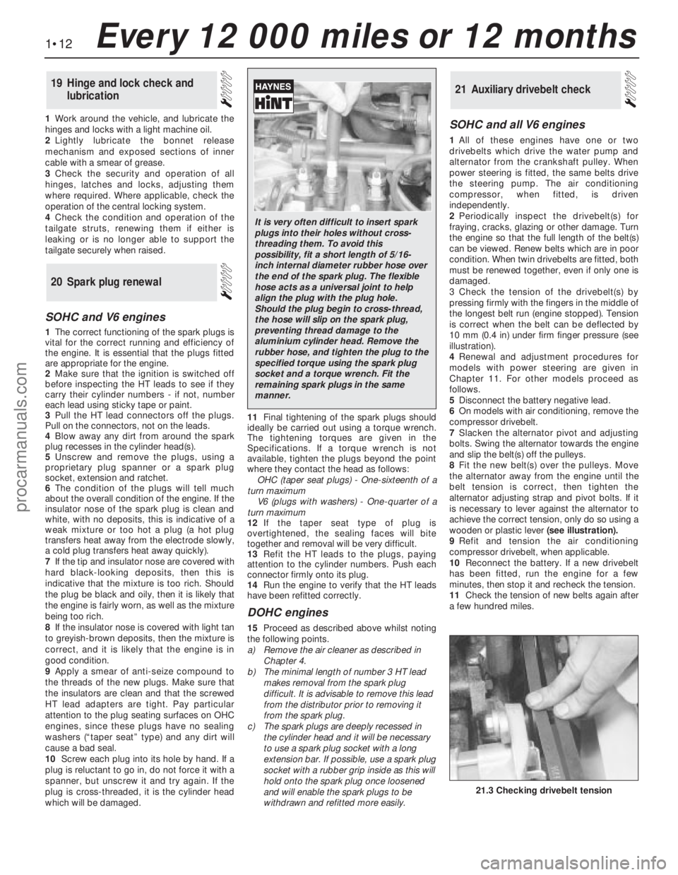
3Check the tension of the drivebelt(s) by
pressing firmly with the fingers in the middle of
the longest belt run (engine stopped). Tension
is correct when the belt can be deflected by
10 mm (0.4 in) under firm finger pressure (see
illustration).
4Renewal and adjustment procedures for
models with power steering are given in
Chapter 11. For other models proceed as
follows.
5Disconnect the battery negative lead.
6On models with air conditioning, remove the
compressor drivebelt.
7Slacken the alternator pivot and adjusting
bolts. Swing the alternator towards the engine
and slip the belt(s) off the pulleys.
8Fit the new belt(s) over the pulleys. Move
the alternator away from the engine until the
belt tension is correct, then tighten the
alternator adjusting strap and pivot bolts. If it
is necessary to lever against the alternator to
achieve the correct tension, only do so using a
wooden or plastic lever(seeillustration).
9Refit and tension the air conditioning
compressor drivebelt, when applicable.
10Reconnect the battery. If a new drivebelt
has been fitted, run the engine for a few
minutes, then stop it and recheck the tension.
11Check the tension of new belts again after
a few hundred miles.
21Auxiliary drivebelt check
20Spark plug renewal
19Hinge and lock check and
lubrication
1•12Every 12 000 miles or 12 months
21.3 Checking drivebelt tension
It is very often difficult to insert spark
plugs into their holes without cross-
threading them. To avoid this
possibility, fit a short length of 5/16-
inch internal diameter rubber hose over
the end of the spark plug. The flexible
hose acts as a universal joint to help
align the plug with the plug hole.
Should the plug begin to cross-thread,
the hose will slip on the spark plug,
preventing thread damage to the
aluminium cylinder head. Remove the
rubber hose, and tighten the plug to the
specified torque using the spark plug
socket and a torque wrench. Fit the
remaining spark plugs in the same
manner.
procarmanuals.com
Page 41 of 255

the Specifications and to illustration 44.11:
Stage 1 - Bolts 1 to 6
Stage 2 - Bolts 7 and 8
Stage 3 - Bolts 9 and 10
Stage 4 - Bolts 7 and 8 (again)
12No further tightening of the cylinder head
bolts is required.
13Refit and tension the timing belt as
described in the next Section.
1Fit the camshaft sprocket backplate and
sprocket. Insert the bolt, hold the camshaft or
sprocket and tighten the bolt to the specified
torque. 2Fit the auxiliary shaft sprocket with the ribs
towards the engine. Fit the sprocket bolt and
tighten it to the specified torque,
counterholding the sprocket with a bar
through one of the holes.
3Fit the crankshaft sprocket, chamfered side
inwards.
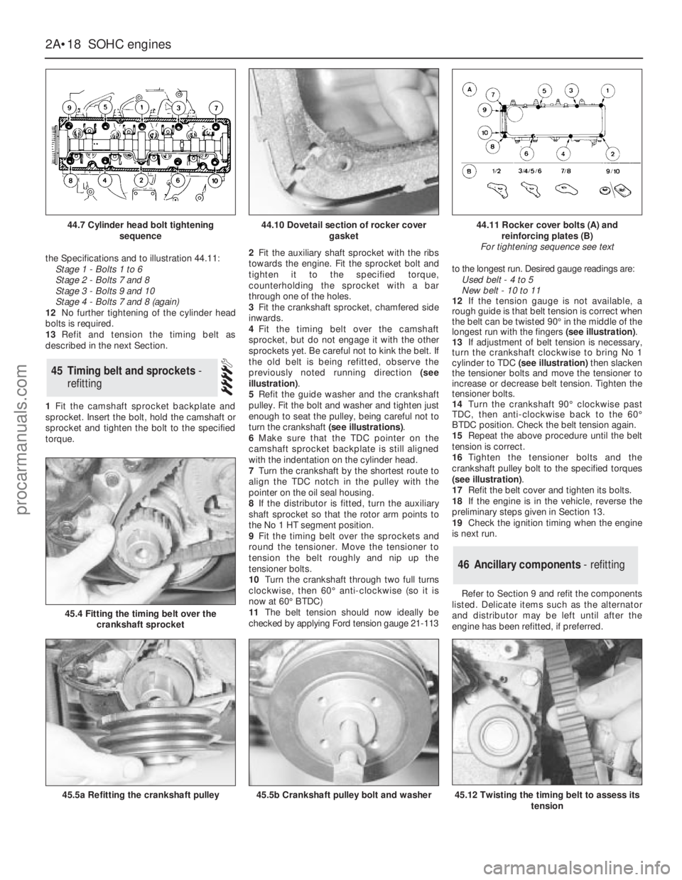
4Fit the timing belt over the camshaft
sprocket, but do not engage it with the other
sprockets yet. Be careful not to kink the belt. If
the old belt is being refitted, observe the
previously noted running direction (see
illustration).
5Refit the guide washer and the crankshaft
pulley. Fit the bolt and washer and tighten just
enough to seat the pulley, being careful not to
turn the crankshaft (see illustrations).
6Make sure that the TDC pointer on the
camshaft sprocket backplate is still aligned
with the indentation on the cylinder head.
7Turn the crankshaft by the shortest route to
align the TDC notch in the pulley with the
pointer on the oil seal housing.
8If the distributor is fitted, turn the auxiliary
shaft sprocket so that the rotor arm points to
the No 1 HT segment position.
9Fit the timing belt over the sprockets and
round the tensioner. Move the tensioner to
tension the belt roughly and nip up the
tensioner bolts.
10Turn the crankshaft through two full turns
clockwise, then 60°anti-clockwise (so it is
now at 60°BTDC)
11The belt tension should now ideally be
checked by applying Ford tension gauge 21-113to the longest run. Desired gauge readings are:
Used belt - 4 to 5
New belt - 10 to 11
12If the tension gauge is not available, a
rough guide is that belt tension is correct when
the belt can be twisted 90°in the middle of the
longest run with the fingers (see illustration).
13If adjustment of belt tension is necessary,
turn the crankshaft clockwise to bring No 1
cylinder to TDC(see illustration)then slacken
the tensioner bolts and move the tensioner to
increase or decrease belt tension. Tighten the
tensioner bolts.
14Turn the crankshaft 90°clockwise past
TDC, then anti-clockwise back to the 60°
BTDC position. Check the belt tension again.
15Repeat the above procedure until the belt
tension is correct.
16Tighten the tensioner bolts and the
crankshaft pulley bolt to the specified torques
(see illustration).
17Refit the belt cover and tighten its bolts.
18If the engine is in the vehicle, reverse the
preliminary steps given in Section 13.
19Check the ignition timing when the engine
is next run.
Refer to Section 9 and refit the components
listed. Delicate items such as the alternator
and distributor may be left until after the
engine has been refitted, if preferred.
46Ancillary components - refitting
45Timing belt and sprockets -
refitting
2A•18SOHCengines
44.7 Cylinder head bolt tightening
sequence
45.4 Fitting the timing belt over the
crankshaft sprocket
45.5a Refitting the crankshaft pulley45.5b Crankshaft pulley bolt and washer45.12 Twisting the timing belt to assess its
tension
44.10 Dovetail section of rocker cover
gasket44.11 Rocker cover bolts (A) and
reinforcing plates (B)
For tightening sequence see text
procarmanuals.com
Page 155 of 255

7Unbolt the guide plate from the body on the
side concerned.
8Carefully lower the jack until the spring is no
longer under tension. Remove the spring and
the rubber buffer.
9Refit by reversing the removal operations,
tightening all fastenings to the specified torque
when known.
Note: Ford tool No 15-014, or locally made
equivalent, will be required for this job.
1Raise and support the rear of the vehicle.
2Flatten the lockwasher which secures the
guide plate centre bolt. Remove the centre
bolt and the two bolts which hold the guide
plate to the floor; remove the guide plate.
3Wedge a piece of wood between the
crossmember and the floor.
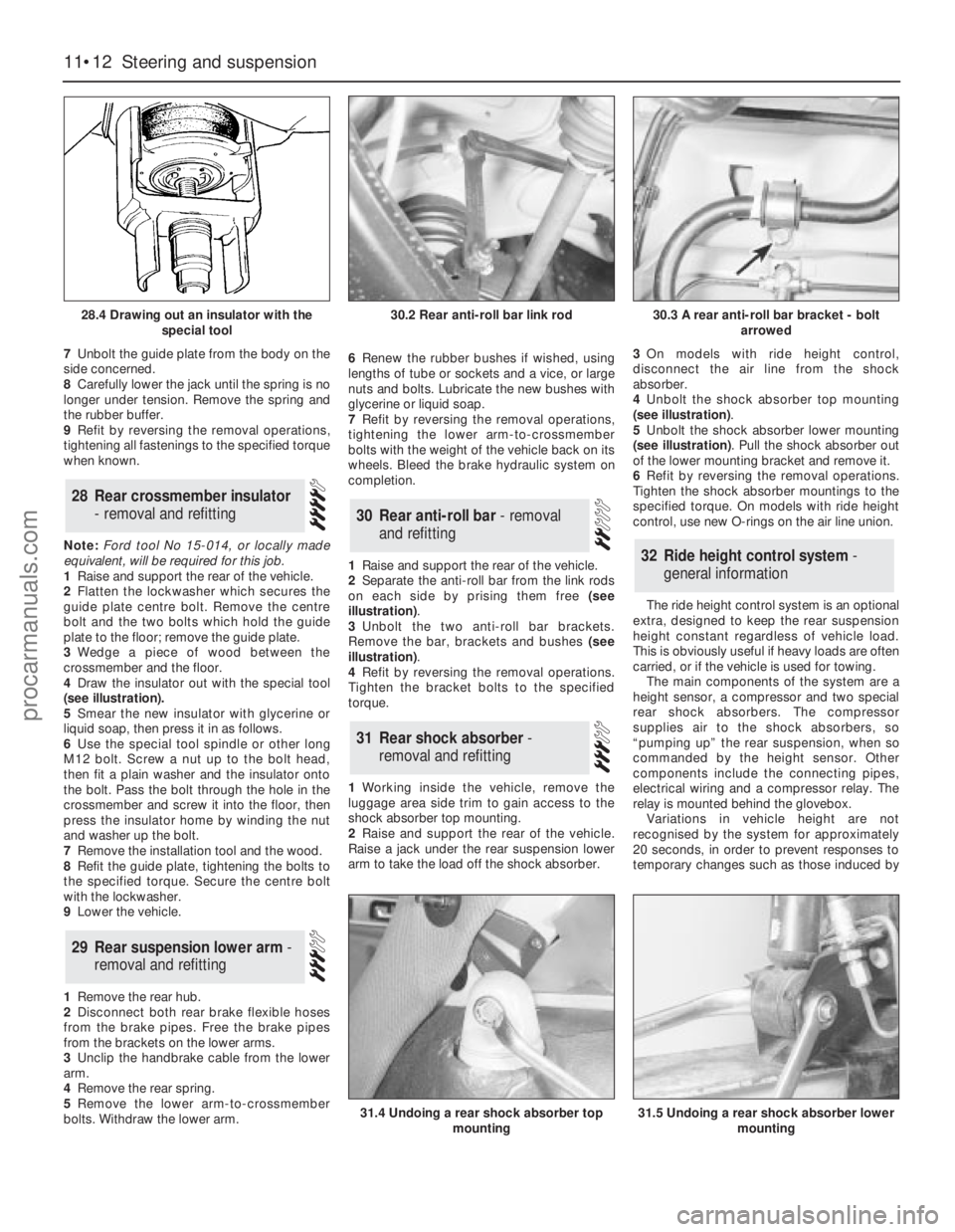
4Draw the insulator out with the special tool
(see illustration).
5Smear the new insulator with glycerine or
liquid soap, then press it in as follows.
6Use the special tool spindle or other long
M12 bolt. Screw a nut up to the bolt head,
then fit a plain washer and the insulator onto
the bolt. Pass the bolt through the hole in the
crossmember and screw it into the floor, then
press the insulator home by winding the nut
and washer up the bolt.
7Remove the installation tool and the wood.
8Refit the guide plate, tightening the bolts to
the specified torque. Secure the centre bolt
with the lockwasher.
9Lower the vehicle.
1Remove the rear hub.
2Disconnect both rear brake flexible hoses
from the brake pipes. Free the brake pipes
from the brackets on the lower arms.
3Unclip the handbrake cable from the lower
arm.
4Remove the rear spring.
5Remove the lower arm-to-crossmember
bolts. Withdraw the lower arm.6Renew the rubber bushes if wished, using
lengths of tube or sockets and a vice, or large
nuts and bolts. Lubricate the new bushes with
glycerine or liquid soap.
7Refit by reversing the removal operations,
tightening the lower arm-to-crossmember
bolts with the weight of the vehicle back on its
wheels. Bleed the brake hydraulic system on
completion.
1Raise and support the rear of the vehicle.
2Separate the anti-roll bar from the link rods
on each side by prising them free (see
illustration).
3Unbolt the two anti-roll bar brackets.
Remove the bar, brackets and bushes (see
illustration).
4Refit by reversing the removal operations.
Tighten the bracket bolts to the specified
torque.
1Working inside the vehicle, remove the
luggage area side trim to gain access to the
shock absorber top mounting.
2Raise and support the rear of the vehicle.
Raise a jack under the rear suspension lower
arm to take the load off the shock absorber.3On models with ride height control,
disconnect the air line from the shock
absorber.
4Unbolt the shock absorber top mounting
(see illustration).
5Unbolt the shock absorber lower mounting
(see illustration). Pull the shock absorber out
of the lower mounting bracket and remove it.
6Refit by reversing the removal operations.
Tighten the shock absorber mountings to the
specified torque. On models with ride height
control, use new O-rings on the air line union.
The ride height control system is an optional
extra, designed to keep the rear suspension
height constant regardless of vehicle load.
This is obviously useful if heavy loads are often
carried, or if the vehicle is used for towing.
The main components of the system are a
height sensor, a compressor and two special
rear shock absorbers. The compressor
supplies air to the shock absorbers, so
“pumping up” the rear suspension, when so
commanded by the height sensor. Other
components include the connecting pipes,
electrical wiring and a compressor relay. The
relay is mounted behind the glovebox.
Variations in vehicle height are not
recognised by the system for approximately
20 seconds, in order to prevent responses to
temporary changes such as those induced by
32Ride height control system -
general information
31Rear shock absorber -
removal and refitting
30Rear anti-roll bar - removal
and refitting
29Rear suspension lower arm -
removal and refitting
28Rear crossmember insulator
- removal and refitting
11•12Steering and suspension
28.4 Drawing out an insulator with the
special tool
31.4 Undoing a rear shock absorber top
mounting31.5 Undoing a rear shock absorber lower
mounting
30.2 Rear anti-roll bar link rod30.3 A rear anti-roll bar bracket - bolt
arrowed
procarmanuals.com