1985 FORD GRANADA dead battery
[x] Cancel search: dead batteryPage 29 of 255

14Take the weight of the engine and remove
the two engine bearer-to-mounting nuts.
15Lift the engine/transmission, at the same
time lowering the trolley jack. Draw the unit
forwards and lift it out of the engine bay.
16Temporarily refit the anti-roll bar if the
vehicle is to be moved.
1With the engine and gearbox on the bench,
remove the starter motor.
2Remove the bolt from the engine adapter plate.
3Remove the bracing strap and the
remaining engine-to-bellhousing bolts.
4With the aid of an assistant draw the
gearbox off the engine. Do not allow the weight
of the gearbox to hang on the input shaft.
1It is best to mount the engine on a
dismantling stand, but if this is not available,
stand the engine on a strong bench at a
comfortable working height. Failing this, it will
have to be stripped down on the floor.
2Cleanliness is most important, and if the
engine is dirty, it should be cleaned with
paraffin while keeping it in an upright position.
3Avoid working with the engine on a concrete
floor, as grit can be a real source of trouble.
4As parts are removed, clean them in paraffin.
However, do not immerse parts with internal
oilways in paraffin as it is difficult to remove,
usually requiring a high pressure hose.
5It is advisable to have suitable containers to
hold small items according to their use, as this
will help when reassembling the engine and
also prevent possible losses.
6Always obtain complete sets of gaskets
when the engine is being dismantled, but
retain the old gaskets with a view of using
them as a pattern to make a replacement if a
new one is not available.7When possible, refit nuts, bolts and washers
in their location after being removed, as this
helps protect the threads and will also be
helpful when reassembling the engine.
8Retain unserviceable components in order
to compare them with the new parts supplied.
9A Torx key, size T55, will be needed for
dealing with the cylinder head bolts. A 12-
spline key (to fit bolt size M8) will be needed
for the oil pump bolts. Other Torx and 12-
spline bolts may be encountered; sets of the
keys required to deal with them are available
from most motor accessory shops and tool
factors.
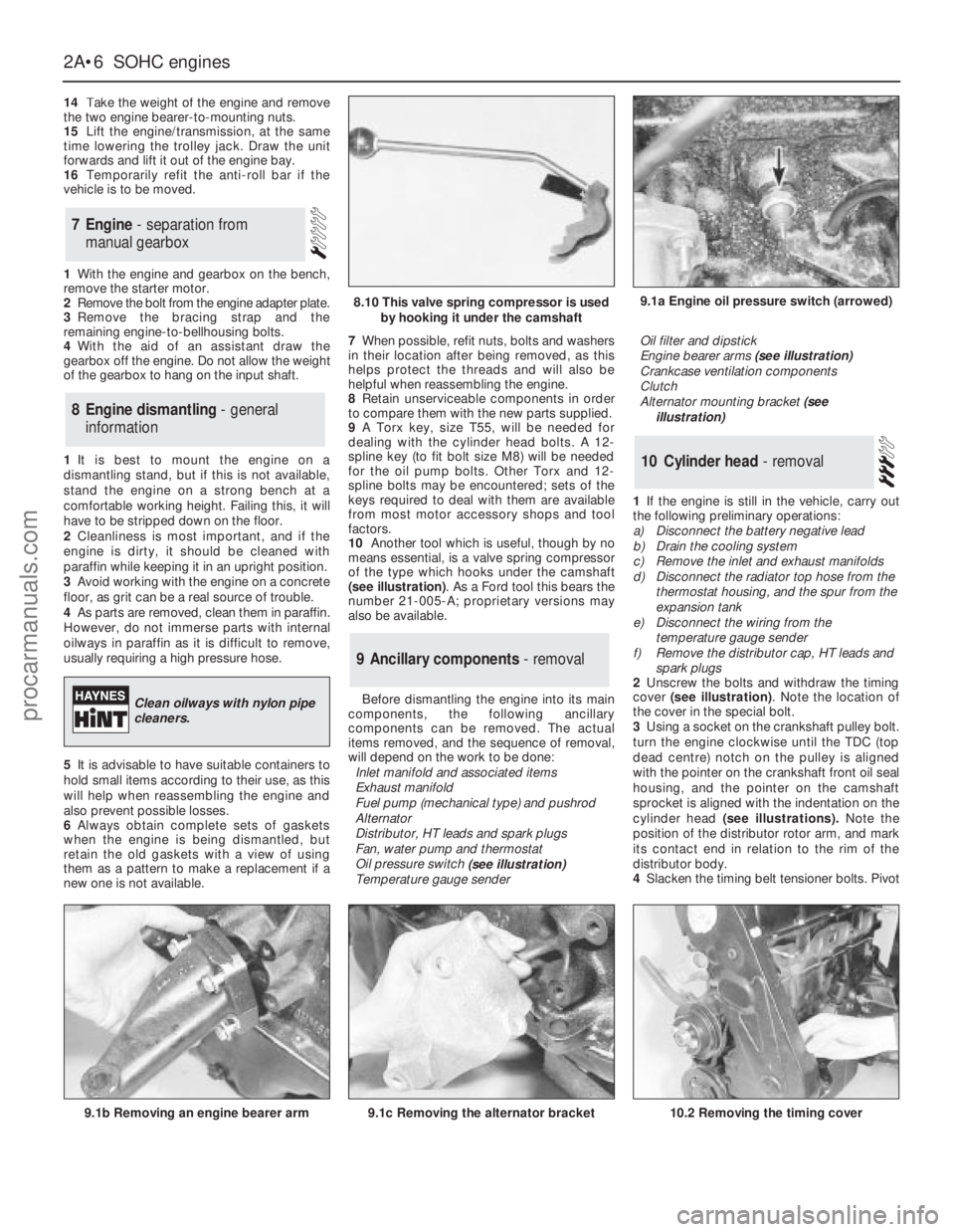
10Another tool which is useful, though by no
means essential, is a valve spring compressor
of the type which hooks under the camshaft
(see illustration). As a Ford tool this bears the
number 21-005-A; proprietary versions may
also be available.
Before dismantling the engine into its main
components, the following ancillary
components can be removed. The actual
items removed, and the sequence of removal,
will depend on the work to be done:
Inlet manifold and associated items
Exhaust manifold
Fuel pump (mechanical type) and pushrod
Alternator
Distributor, HT leads and spark plugs
Fan, water pump and thermostat
Oil pressure switch
(see illustration)
Temperature gauge senderOil filter and dipstick
Engine bearer arms (see illustration)
Crankcase ventilation components
Clutch
Alternator mounting bracket (see
illustration)
1If the engine is still in the vehicle, carry out
the following preliminary operations:
a)Disconnect the battery negative lead
b)Drain the cooling system
c)Remove the inlet and exhaust manifolds
d)Disconnect the radiator top hose from the
thermostat housing, and the spur from the
expansion tank
e)Disconnect the wiring from the
temperature gauge sender
f)Remove the distributor cap, HT leads and
spark plugs
2Unscrew the bolts and withdraw the timing
cover (see illustration). Note the location of
the cover in the special bolt.
3Using a socket on the crankshaft pulley bolt.
turn the engine clockwise until the TDC (top
dead centre) notch on the pulley is aligned
with the pointer on the crankshaft front oil seal
housing, and the pointer on the camshaft
sprocket is aligned with the indentation on the
cylinder head (see illustrations).Note the
position of the distributor rotor arm, and mark
its contact end in relation to the rim of the
distributor body.
4Slacken the timing belt tensioner bolts. Pivot
10Cylinder head - removal
9Ancillary components - removal
8Engine dismantling - general
information
7Engine - separation from
manual gearbox
2A•6SOHCengines
9.1a Engine oil pressure switch (arrowed)
9.1b Removing an engine bearer arm9.1c Removing the alternator bracket
8.10 This valve spring compressor is used
by hooking it under the camshaft
Clean oilways with nylon pipe
cleaners.
10.2 Removing the timing cover
procarmanuals.com
Page 31 of 255

1Remove the camshaft as described in the
previous Section. (If tool 21-005-A is available,
leave the camshaft in place until the valves
have been removed).
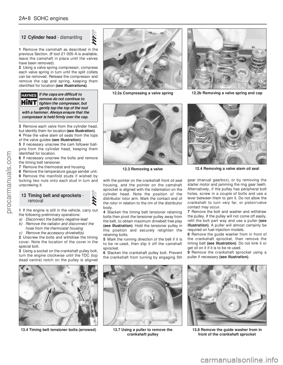
2Using a valve spring compressor, compress
each valve spring in turn until the split collets
can be removed. Release the compressor and
remove the cap and spring, keeping them
identified for location (see illustrations).
3Remove each valve from the cylinder head,
but identify them for location (see illustration).
4Prise the valve stem oil seals from the tops
of the valve guides (see illustration).
5If necessary unscrew the cam follower ball-
pins from the cylinder head, keeping them
identified for location.
6If necessary unscrew the bolts and remove
the timing belt tensioner.
7Remove the thermostat and housing.
8Remove the temperature gauge sender unit.
9Remove the manifold studs if wished by
locking two nuts onto each stud in turn and
unscrewing it.
1If the engine is still in the vehicle, carry out
the following preliminary operations:
a)Disconnect the battery negative lead
b)Remove the radiator and disconnect the
hose from the thermostat housing
c)Remove the accessory drivebelt(s)
2Unscrew the bolts and withdraw the timing
cover. Note the location of the cover in the
special bolt.
3Using a socket on the crankshaft pulley bolt,
turn the engine clockwise until the TDC (top
dead centre) notch on the pulley is alignedwith the pointer on the crankshaft front oil seal
housing, and the pointer on the camshaft
sprocket is aligned with the indentation on the
cylinder head. Note the position of the
distributor rotor arm. Mark the contact end of
the rotor in relation to the rim of the distributor
body.
4Slacken the timing belt tensioner retaining
bolts then pivot the tensioner pulley away from
the belt, to obtain maximum drivebelt free play
(see illustration). Hold the tensioner pulley in
this position and securely retighten the
retaining bolts.
5Mark the running direction of the belt if it is
to be re-used, then slip it off the camshaft
sprocket.
6Slacken the crankshaft pulley bolt. Prevent
the crankshaft from turning by engaging 5thgear (manual gearbox), or by removing the
starter motor and jamming the ring gear teeth.
Alternatively, if the pulley has peripheral bolt
holes, screw in a couple of bolts and use a
lever between them to jam it. Do not allow the
crankshaft to turn very far, or piston/valve
contact may occur.
7Remove the bolt and washer and withdraw
the pulley. If the pulley will not come off easily,
refit the bolt part way and use a puller (see
illustration). A puller will almost certainly be
required on fuel-injection models.
8Remove the guide washer from in front of
the crankshaft sprocket, then remove the
timing belt (see illustration). Do not kink it or
get oil on it if it is to be re-used.
9Remove the crankshaft sprocket using a
puller if necessary (see illustration).
13Timing belt and sprockets -
removal
12Cylinder head - dismantling
2A•8SOHCengines
12.2a Compressing a valve spring
13.4 Timing belt tensioner bolts (arrowed)13.7 Using a puller to remove the
crankshaft pulley
12.4 Removing a valve stem oil seal
13.8 Remove the guide washer from in
front of the crankshaft sprocket
12.2b Removing a valve spring and cap
12.3 Removing a valve
If the caps are difficult to
remove do not continue to
tighten the compressor, but
gently tap the top of the tool
with a hammer. Always ensure that the
compressor is held firmly over the cap.
procarmanuals.com
Page 120 of 255

engine coolant temperature sensor. The
crankshaft speed/position sensor is activated
by a toothed disc on the rear of the crankshaft,
inside the cylinder block. The disc has 35
equally spaced teeth (one every 10°), with a
gap in the 36th position. The gap is used by
the sensor to determine the crankshaft
position relative to Top Dead Centre (TDC) of
No 1 piston.
The ignition advance is a function of the
ESC II module, and is controlled by vacuum.
The module is connected to the carburettor by
a vacuum pipe, and a transducer in the
module translates the vacuum signal into an
electrical voltage. From the vacuum signal, the
module determines engine load; engine speed
and temperature are determined from the
crankshaft speed/position sensor and the
engine coolant temperature sensor. The
module has a range of spark advance settings
stored in the memory, and a suitable setting is
selected for the relevant engine speed, load
and temperature. The degree of advance can
thus be constantly varied to suit the prevailing
engine speed and load conditions.
On DOHC fuel-injected engines, a
development of the EEC IV (Electronic Engine
Control IV) engine management system is
used to control both the ignition and fuel-
injection systems. The EEC IV module receives
information from a crankshaft speed/position
sensor (the same as that fitted to the
carburettor models), a throttle position sensor,
an engine coolant temperature sensor, a fuel
temperature sensor, an air charge temperature
sensor, a Manifold Absolute Pressure (MAP)
sensor, and a vehicle speed sensor (mounted
on the gearbox). Additionally, on models with
a catalytic converter, an additional input is
supplied to the EEC IV module from an
exhaust gas oxygen (HEGO) sensor. On
models with automatic transmission,
additional sensors are fitted to the
transmission to inform the EEC IV module
when the transmission is in neutral, and when
the downshift is being operated.
The module provides outputs to control the
fuel pump, fuel-injectors, idle speed, ignition
system and automatic transmission .
Additionally, on models with air conditioning,
the EEC IV module disengages the air
conditioning compressor clutch when starting
the engine or when the engine is suddenly
accelerated. On models fitted with a catalytic
converter, the EEC IV module also controls the
carbon canister purge solenoid valve.
Using the inputs from the various sensors,
the EEC IV module computes the optimum
ignition advance, and fuel-injector pulse
duration to suit the prevailing engine
conditions.
On 2.4 & 2.9 litre V6 engines, the system
operates in much the same way as that fitted
to the DOHC fuel-injected engine, noting the
following points.
a)There is no crankshaft speed/position
sensor.
b)The vehicle speed sensor is only fitted to
models equipped with a catalytic
converter.Precautions
ESC II module
Although it will tolerate all normal under-
bonnet conditions, the ESC II module may be
adversely affected by water entry during
steam cleaning or pressure washing of the
engine bay.
If cleaning the engine bay, therefore, take
care not to direct jets of water or steam at the
ESC II module. If this cannot be avoided,
remove the module completely, and protect its
multi-plug with a plastic bag.
Ignition system HT voltage
Take care to avoid receiving electric shocks
from the HT side of the ignition system. Do not
handle HT leads, or touch the distributor or
coil, when the engine is running. When tracing
faults in the HT system, use well insulated
tools to manipulate live leads. Electronic
ignition HT voltage could prove fatal.
Electronic ignition systems
General
Further details of the various systems are
given in the relevant Sections of this Chapter.
While some repair procedures are given, the
usual course of action is to renew the
component concerned. The owner whose
interest extends beyond mere component
renewal should obtain a copy of the
Automobile Electrical & Electronic Systems
Manual, available from the publishers of this
manual.
It is necessary to take extra care when
working on the electrical system, to avoid
damage to semi-conductor devices (diodes
and transistors), and to avoid the risk of
personal injury. In addition to the precautions
given in Safety first!at the beginning of this
manual, observe the following when working
on the system:
Always remove rings, watches, etc before
working on the electrical system.Even with the
battery disconnected, capacitive discharge
could occur if a component’s live terminal is
earthed through a metal object. This could
cause a shock or nasty burn.
Do not reverse the battery connections.
Components such as the alternator, electronic
control units, or any other components having
semi-conductor circuitry, could be irreparably
damaged.
If the engine is being started using jump
leads and a slave battery, connect thebatteries positive-to-positiveand negative-to-
negative(see “Jump starting”). This also
applies when connecting a battery charger.
Never disconnect the battery terminals, the
alternator, any electrical wiring, or any test
instruments, when the engine is running.
Do not allow the engine to turn the alternator
when the alternator is not connected.
Never test for alternator output by “flashing”
the output lead to earth.
Never use an ohmmeter of the type
incorporating a hand-cranked generator for
circuit or continuity testing.
Always ensure that the battery negative lead
is disconnected when working on the
electrical system.
Before using electric-arc welding equipment
on the car, disconnect the battery, alternator,
and components such as the fuel-
injection/ignition electronic control unit, to
protect them from the risk of damage.
Refer to Chapter 13
1In normal use the battery should not require
charging from an external source, unless the
vehicle is laid up for long periods, when it
should be recharged every six weeks or so. If
vehicle use consists entirely of short runs in
darkness it is also possible for the battery to
become discharged. Otherwise, a regular
need for recharging points to a fault in the
battery or elsewhere in the charging system.
2There is no need to disconnect the battery
from the vehicle wiring when using a battery
charger, but switch off the ignition and leave
the bonnet open.
3Domestic battery chargers (up to about 6
amps output) may safely be used overnight
without special precautions. Make sure that
the charger is set to deliver 12 volts before
connecting it. Connect the leads (red or
positive to the positive terminal, black or
negative to the negative terminal) before
switching the charger on at the mains.
4When charging is complete, switch off at
the mains beforedisconnecting the charger
from the battery. Remember that the battery
will be giving off hydrogen gas, which is
potentially explosive.
5Charging at a higher rate should only be
carried out under carefully controlled
conditions. Very rapid or “boost” charging
should be avoided if possible, as it is liable to
cause permanent damage to the battery
through overheating.
6During any sort of charging, battery
electrolyte temperature should never exceed
38°C (100°F). If the battery becomes hot, or
the electrolyte is effervescing vigorously,
charging should be stopped.
3Battery - charging
2Electrical fault-finding - general
information
Engine electrical systems 5•3
5
Warning. The voltages produced
by the electronic ignition system
are considerably higher than those
produced by conventional
systems. Extreme care must be taken when
working on the system with the ignition
switched on. Persons with surgically-
implanted cardiac pacemaker devices
should keep well clear of the ignition
circuits, components and test equipment.
procarmanuals.com