1985 FORD GRANADA stop start
[x] Cancel search: stop startPage 17 of 255
Instruments and electrical
equipment
1Check the operation of all instruments and
electrical equipment.
2Make sure that all instruments read
correctly, and switch on all electrical
equipment in turn to check that it functions
properly.
Steering and suspension
3Check for any abnormalities in the steering,
suspension, handling or road “feel”.
4Drive the vehicle, and check that there are
no unusual vibrations or noises.
5Check that the steering feels positive, with
no excessive “sloppiness”, or roughness, and
check for any suspension noises when
cornering, or when driving over bumps.
Drivetrain
6Check the performance of the engine,
clutch, transmission and driveshafts.
7Listen for any unusual noises from the
engine, clutch and transmission.
8Make sure that the engine runs smoothly
when idling, and that there is no hesitation
when accelerating.
9Where applicable, check that the clutch
action is smooth and progressive, that the
drive is taken up smoothly, and that the pedal
travel is not excessive. Also listen for any
noises when the clutch pedal is depressed.
10Check that all gears can be engaged
smoothly, without noise, and that the gear
lever action is not abnormally vague or
“notchy”.
Check the operation and
performance of the braking system
11Make sure that the vehicle does not pull to
one side when braking, and that the wheels do
not lock prematurely when braking hard.
12Check that there is no vibration through
the steering when braking.
13Check that the handbrake operates
correctly, without excessive movement of the
lever, and that it holds the vehicle stationary
on a slope.
14Test the operation of the brake servo unit
as follows. With the engine off, depress the
footbrake four or five times to exhaust the
vacuum. Start the engine, holding the brake
pedal depressed. As the engine starts, there
should be a noticeable “give” in the brake
pedal as vacuum builds up. Allow the engine
to run for at least two minutes, and then
switch it off. If the brake pedal is depressed
now, it should be possible to detect a hiss
from the servo as the pedal is depressed. After
about four or five applications, no further
hissing should be heard, and the pedal should
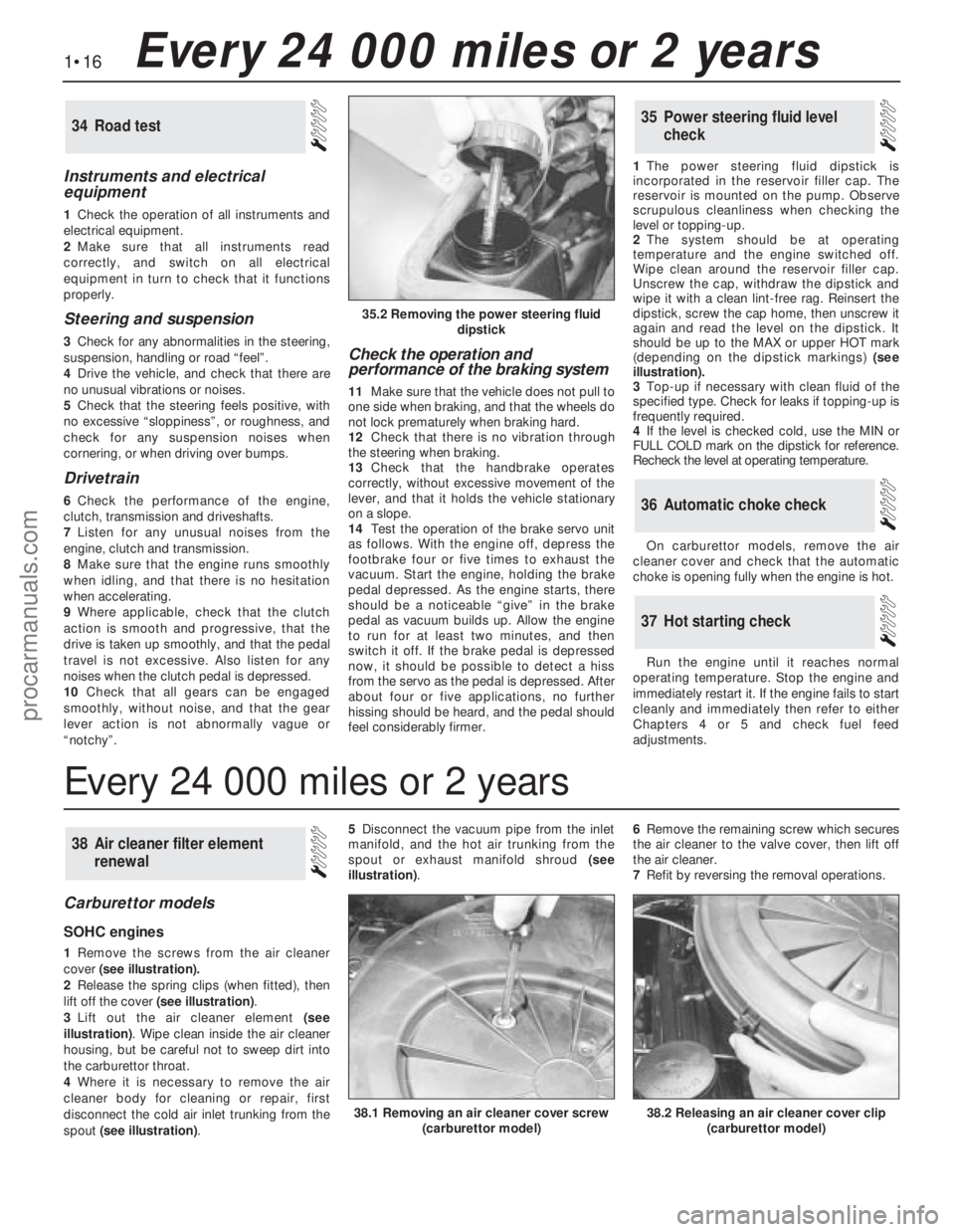
feel considerably firmer.1The power steering fluid dipstick is
incorporated in the reservoir filler cap. The
reservoir is mounted on the pump. Observe
scrupulous cleanliness when checking the
level or topping-up.
2The system should be at operating
temperature and the engine switched off.
Wipe clean around the reservoir filler cap.
Unscrew the cap, withdraw the dipstick and
wipe it with a clean lint-free rag. Reinsert the
dipstick, screw the cap home, then unscrew it
again and read the level on the dipstick. It
should be up to the MAX or upper HOT mark
(depending on the dipstick markings) (see
illustration).
3Top-up if necessary with clean fluid of the
specified type. Check for leaks if topping-up is
frequently required.
4If the level is checked cold, use the MIN or
FULL COLD mark on the dipstick for reference.
Recheck the level at operating temperature.
On carburettor models, remove the air
cleaner cover and check that the automatic
choke is opening fully when the engine is hot.
Run the engine until it reaches normal
operating temperature. Stop the engine and
immediately restart it. If the engine fails to start
cleanly and immediately then refer to either
Chapters 4 or 5 and check fuel feed
adjustments.
37Hot starting check
36Automatic choke check
35Power steering fluid level
check34Road test
Carburettor models
SOHC engines
1Remove the screws from the air cleaner
cover(see illustration).
2Release the spring clips (when fitted), then
lift off the cover (see illustration).
3Lift out the air cleaner element(see
illustration). Wipe clean inside the air cleaner
housing, but be careful not to sweep dirt into
the carburettor throat.
4Where it is necessary to remove the air
cleaner body for cleaning or repair, first
disconnect the cold air inlet trunking from the
spout (see illustration). 5Disconnect the vacuum pipe from the inlet
manifold, and the hot air trunking from the
spout or exhaust manifold shroud(see
illustration). 6Remove the remaining screw which secures
the air cleaner to the valve cover, then lift off
the air cleaner.
7Refit by reversing the removal operations.
38Air cleaner filter element
renewal
1•16Every 24 000 miles or 2 years
35.2 Removing the power steering fluid
dipstick
38.2 Releasing an air cleaner cover clip
(carburettor model)38.1 Removing an air cleaner cover screw
(carburettor model)
Every 24 000 miles or 2 years
procarmanuals.com
Page 21 of 255
12Place a piece of wood in the caliper jaws
to limit piston travel. Keep your fingers clear of
the piston. Have the assistant depress the
brake pedal gentlyin order to move the
caliper piston out.
13With the pedal held depressed, slacken
the bleed screw on the right-hand caliper and
again depress the piston. Tighten the bleed
screw when the piston is retracted. The pedal
can now be released.
14Disconnect the bleed tube. Refit the right-hand brake pad and caliper.
15Remove the left-hand caliper and inboard
pad again. Carry out the operations described
in paragraphs 10 to 14 on the left-hand
caliper.
16Bleed the rear brakes as described in
Chapter 10.
17Refit the front wheels, lower the vehicle
and tighten the wheel nuts.
18Pump the brake pedal to bring the pads
up to the discs, then make a final check of thehydraulic fluid level. Top-up and refit the
reservoir cap.
Camshaft drivebelt renewal is
recommended as a precautionary measure.
Refer to Chapter 2, Part A, Sections 13 and 45
for the full renewal procedure.
45Camshaft drivebelt renewal -
SOHC engines
1Before proceeding, note the precautions
given in Chapter 3, Section 1.
2Disconnect the battery negative lead.
3Remove the expansion tank cap. Take
precautions against scalding if the system is
hot.
4Place a drain pan of adequate capacity
beneath the radiator drain plug. Unscrew the
plug, without removing it, and allow the
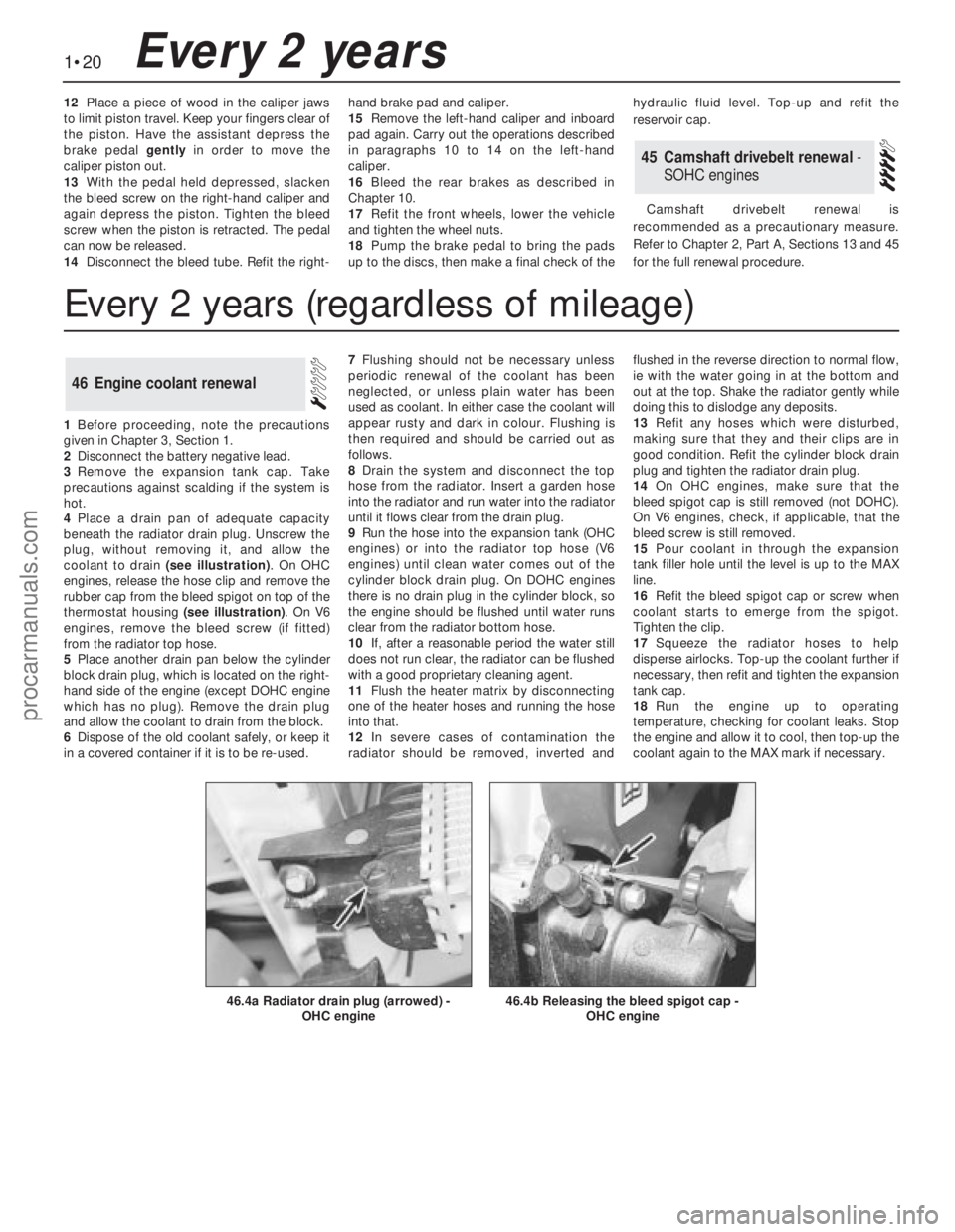
coolant to drain (see illustration). On OHC
engines, release the hose clip and remove the
rubber cap from the bleed spigot on top of the
thermostat housing (see illustration). On V6
engines, remove the bleed screw (if fitted)
from the radiator top hose.
5Place another drain pan below the cylinder
block drain plug, which is located on the right-
hand side of the engine (except DOHC engine
which has no plug). Remove the drain plug
and allow the coolant to drain from the block.
6Dispose of the old coolant safely, or keep it
in a covered container if it is to be re-used.7Flushing should not be necessary unless
periodic renewal of the coolant has been
neglected, or unless plain water has been
used as coolant. In either case the coolant will
appear rusty and dark in colour. Flushing is
then required and should be carried out as
follows.
8Drain the system and disconnect the top
hose from the radiator. Insert a garden hose
into the radiator and run water into the radiator
until it flows clear from the drain plug.
9Run the hose into the expansion tank (OHC
engines) or into the radiator top hose (V6
engines) until clean water comes out of the
cylinder block drain plug. On DOHC engines
there is no drain plug in the cylinder block, so
the engine should be flushed until water runs
clear from the radiator bottom hose.
10If, after a reasonable period the water still
does not run clear, the radiator can be flushed
with a good proprietary cleaning agent.
11Flush the heater matrix by disconnecting
one of the heater hoses and running the hose
into that.
12In severe cases of contamination the
radiator should be removed, inverted andflushed in the reverse direction to normal flow,
ie with the water going in at the bottom and
out at the top. Shake the radiator gently while
doing this to dislodge any deposits.
13Refit any hoses which were disturbed,
making sure that they and their clips are in
good condition. Refit the cylinder block drain
plug and tighten the radiator drain plug.
14On OHC engines, make sure that the
bleed spigot cap is still removed (not DOHC).
On V6 engines, check, if applicable, that the
bleed screw is still removed.
15Pour coolant in through the expansion
tank filler hole until the level is up to the MAX
line.
16Refit the bleed spigot cap or screw when
coolant starts to emerge from the spigot.
Tighten the clip.
17Squeeze the radiator hoses to help
disperse airlocks. Top-up the coolant further if
necessary, then refit and tighten the expansion
tank cap.
18Run the engine up to operating
temperature, checking for coolant leaks. Stop
the engine and allow it to cool, then top-up the
coolant again to the MAX mark if necessary.
46Engine coolant renewal
1•20Every 2 years
46.4b Releasing the bleed spigot cap -
OHC engine46.4a Radiator drain plug (arrowed) -
OHC engine
Every 2 years (regardless of mileage)
procarmanuals.com
Page 43 of 255
See Chapter 1, Section 23.
1Make a final check to ensure that everything
has been reconnected to the engine and that no
rags or tools have been left in the engine bay.
2Check that oil and coolant levels are
correct.
3Start the engine. This may take a little longer
than usual as fuel is pumped up to the engine.
4Check that the oil pressure light goes out
when the engine starts.
5Run the engine at a fast tickover and check
for leaks of oil, fuel and coolant. Also check
power steering and transmission fluid cooler
unions, when applicable. Some smoke and
odd smells may be experienced as assembly
lubricant burns off the exhaust manifold and
other components.6Bring the engine to operating temperature.
Check the ignition timing then adjust the idle
speed (if applicable) and mixture.
7Stop the engine and allow it to cool, then re-
check the oil and coolant levels.
8If new bearings, pistons etc have been
fitted, the engine should be run in at reduced
speeds and loads for the first 500 miles (800
km) or so. It is beneficial to change the engine
oil and filter after this mileage.
1When engine performance is down, or if
misfiring occurs which cannot be attributed to
the ignition or fuel system, a compression test
can provide diagnostic clues. If the test is
performed regularly it can give warning of
trouble before any other symptoms become
apparent.
2The engine must be at operating
temperature, the battery must be fully charged
and the spark plugs must be removed. The
services of an assistant will also be required.
3Disable the ignition system by dismantlingthe coil LT feed. Fit the compression tester to
No 1 spark plug hole. (The type of tester which
screws into the spark plug hole is to be
preferred.)
4Have the assistant hold the throttle wide
open and crank the engine on the starter.
Record the highest reading obtained on the
compression tester.
5Repeat the test on the remaining cylinders,
recording the pressure developed in each.
6Desired pressures are given in the
Specifications. If the pressure in any cylinder
is low, introduce a teaspoonful of clean engine
oil into the spark plug hole and repeat the test.
7If the addition of oil temporarily improves
the compression pressure, this indicates that
bore or piston wear was responsible for the
pressure loss. No improvement suggests that
leaking or burnt valves, or a blown head
gasket, may be to blame.
8A low reading from two adjacent cylinders is
almost certainly due to the head gasket
between them having blown.
9On completion of the test, refit the spark
plugs and reconnect the coil LT feed.
52Compression test -
description and interpretation
51Initial start-up after overhaul
or major repair
50Valve clearances - checking
and adjustment
2A•20SOHCengines
procarmanuals.com
Page 48 of 255
27Remove the starter motor.
28Remove the exhaust downpipe.
29Ensure that the steering wheel is
positioned in the straight-ahead position then,
using a dab of paint or a suitable marker pen,
make alignment marks between the
intermediate shaft lower clamp and steering
gear pinion. Slacken and remove the lower
clamp bolt then disconnect the intermediate
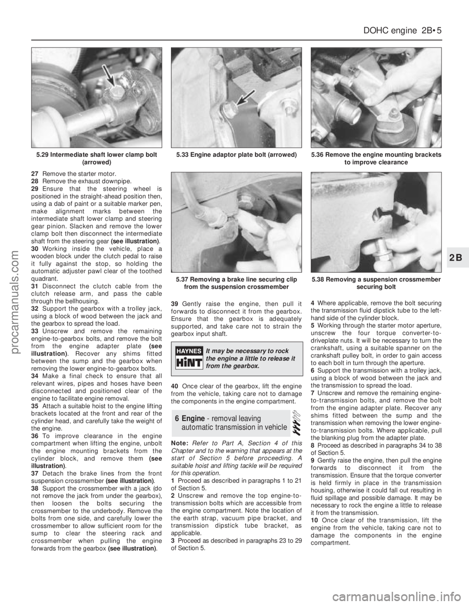
shaft from the steering gear (see illustration).
30Working inside the vehicle, place a
wooden block under the clutch pedal to raise
it fully against the stop, so holding the
automatic adjuster pawl clear of the toothed
quadrant.
31Disconnect the clutch cable from the
clutch release arm, and pass the cable
through the bellhousing.
32Support the gearbox with a trolley jack,
using a block of wood between the jack and
the gearbox to spread the load.
33Unscrew and remove the remaining
engine-to-gearbox bolts, and remove the bolt
from the engine adapter plate (see
illustration). Recover any shims fitted
between the sump and the gearbox when
removing the lower engine-to-gearbox bolts.
34Make a final check to ensure that all
relevant wires, pipes and hoses have been
disconnected and positioned clear of the
engine to facilitate engine removal.
35Attach a suitable hoist to the engine lifting
brackets located at the front and rear of the
cylinder head, and carefully take the weight of
the engine.
36To improve clearance in the engine
compartment when lifting the engine, unbolt
the engine mounting brackets from the
cylinder block, and remove them (see
illustration).
37Detach the brake lines from the front
suspension crossmember (see illustration).
38Support the crossmember with a jack (do
not remove the jack from under the gearbox),
then loosen the bolts securing the
crossmember to the underbody. Remove the
bolts from one side, and carefully lower the
crossmember to allow sufficient room for the
sump to clear the steering rack and
crossmember when pulling the engine
forwards from the gearbox (see illustration).39Gently raise the engine, then pull it
forwards to disconnect it from the gearbox.
Ensure that the gearbox is adequately
supported, and take care not to strain the
gearbox input shaft.
40Once clear of the gearbox, lift the engine
from the vehicle, taking care not to damage
the components in the engine compartment.
Note:Refer to Part A, Section 4 of this
Chapter and to the warning that appears at the
start of Section 5 before proceeding. A
suitable hoist and lifting tackle will be required
for this operation.
1Proceed as described in paragraphs 1 to 21
of Section 5.
2Unscrew and remove the top engine-to-
transmission bolts which are accessible from
the engine compartment. Note the location of
the earth strap, vacuum pipe bracket, and
transmission dipstick tube bracket, as
applicable.
3Proceed as described in paragraphs 23 to 29
of Section 5.4Where applicable, remove the bolt securing
the transmission fluid dipstick tube to the left-
hand side of the cylinder block.
5Working through the starter motor aperture,
unscrew the four torque converter-to-
driveplate nuts. It will be necessary to turn the
crankshaft, using a suitable spanner on the
crankshaft pulley bolt, in order to gain access
to each bolt in turn through the aperture.
6Support the transmission with a trolley jack,
using a block of wood between the jack and
the transmission to spread the load.
7Unscrew and remove the remaining engine-
to-transmission bolts, and remove the bolt
from the engine adapter plate. Recover any
shims fitted between the sump and the
transmission when removing the lower engine-
to-transmission bolts. Where applicable, pull
the blanking plug from the adapter plate.
8Proceed as described in paragraphs 34 to 38
of Section 5.
9Gently raise the engine, then pull the engine
forwards to disconnect it from the
transmission. Ensure that the torque converter
is held firmly in place in the transmission
housing, otherwise it could fall out resulting in
fluid spillage and possible damage. It may be
necessary to rock the engine a little to release
it from the transmission.
10Once clear of the transmission, lift the
engine from the vehicle, taking care not to
damage the components in the engine
compartment.
6Engine - removal leaving
automatic transmission in vehicle
DOHCengine 2B•5
2B
5.29 Intermediate shaft lower clamp bolt
(arrowed)5.33 Engine adaptor plate bolt (arrowed)5.36 Remove the engine mounting brackets
to improve clearance
5.37 Removing a brake line securing clip
from the suspension crossmember5.38 Removing a suspension crossmember
securing bolt
It may be necessary to rock
the engine a little to release it
from the gearbox.
procarmanuals.com
Page 61 of 255
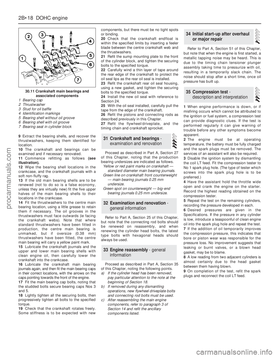
9Extract the bearing shells, and recover the
thrustwashers, keeping them identified for
location.
10The crankshaft and bearings can be
examined and if necessary renovated.
11Commence refitting as follows(see
illustration).
12Wipe the bearing shell locations in the
crankcase, and the crankshaft journals with a
soft non-fluffy rag.
13If the old main bearing shells are to be
renewed (not to do so is a false economy,
unless they are virtually new) fit the five upper
halves of the main bearing shells to their
locations in the crankcase.
14Fit the thrustwashers to the centre main
bearing location, using a little grease to retain
them if necessary. The oil grooves in the
thrustwashers must face outwards (ie facing
the crankshaft webs). Note that where
standard thrustwashers have been fitted in
production, the centre main bearing is
unmarked, but if oversize (0.38 mm)
thrustwashers have been fitted, the centre
main bearing will carry a yellow paint mark.
15Lubricate the crankshaft journals and the
upper and lower main bearing shells with
clean engine oil, then carefully lower the
crankshaft into the crankcase.
16Lubricate the crankshaft main bearing
journals again, and then fit the main bearing caps
in their correct locations, with the arrows on the
caps pointing towards the front of the engine.
17Fit the main bearing cap bolts, noting that
the studded bolts secure bearing caps Nos 3
and 5.
18Lightly tighten all the securing bolts, then
progressively tighten all bolts to the specified
torque.
19Check that the crankshaft rotates freely.
Some stiffness is to be expected with newcomponents, but there must be no tight spots
or binding.
20Check that the crankshaft endfloat is
within the specified limits by inserting a feeler
blade between the centre crankshaft web and
the thrustwashers.
21Refit the sump mounting plate to the front
of the cylinder block, and tighten the securing
bolts to the specified torque.
22Carefully wind a thin layer of tape around
the rear edge of the crankshaft to protect the
oil seal lips as the rear oil seal is installed.
23Refit the crankshaft rear oil seal housing,
using a new gasket, and tighten the securing
bolts to the specified torque.
24Install the new oil seal with reference to
Section 24.
25With the oil seal installed, carefully pull the
tape from the edge of the crankshaft.
26Refit the pistons and connecting rods as
described previously in this Chapter.
27Refit the flywheel/driveplate, and the
timing chain and crankshaft sprocket.
Proceed as described in Part A, Section 27
of this Chapter, noting that the production
bearing undersizes are indicated as follows.
Yellow or red paint marks on crankshaft —
standard diameter main bearing journals.
Green line on crankshaft front counterweight
— main bearing journals 0.25 mm
undersize.
Green spot on counterweight — big-end
bearing journals 0.25 mm undersize.
Refer to Part A, Section 25 of this Chapter,
but note that the connecting rod bolts should
be renewed on reassembly, and when
renewing the cylinder head bolts, the latest
type bolts with hexagonal heads should
always be used.
Proceed as described in Part A, Section 35
of this Chapter, noting the following points.
a)If the cylinder head has been removed,
pay particular attention to the note at the
beginning of Section 18.
b)If removed during any dismantling
operations, new flywheel driveplate bolts
and connecting rod bolts must be used.
c)After reassembling the main engine
components, refer to paragraph 3 of
Section 14 and refit the ancillary
components listed.Refer to Part A, Section 51 of this Chapter,
but note that when the engine is first started, a
metallic tapping noise may be heard. This is
due to the timing chain tensioner plunger
assembly taking time to pressurize with oil,
resulting in a temporarily slack chain. The
noise should stop after a short time, once oil
pressure has built up.
1When engine performance is down, or if
misfiring occurs which cannot be attributed to
the ignition or fuel system, a compression test
can provide diagnostic clues. If the test is
performed regularly it can give warning of
trouble before any other symptoms become
apparent.
2The engine must be at operating
temperature, the battery must be fully charged
and the spark plugs must be removed. The
services of an assistant will also be required.
3Disable the ignition system by dismantling
the coil LT feed. Fit the compression tester to
No 1 spark plug hole. (The type of tester which
screws into the spark plug hole is to be
preferred.)
4Have the assistant hold the throttle wide
open and crank the engine on the starter.
Record the highest reading obtained on the
compression tester.
5Repeat the test on the remaining cylinders,
recording the pressure developed in each.
6Desired pressures are given in the
Specifications. If the pressure in any cylinder
is low, introduce a teaspoonful of clean engine
oil into the spark plug hole and repeat the test.
7If the addition of oil temporarily improves
the compression pressure, this indicates that
bore or piston wear was responsible for the
pressure loss. No improvement suggests that
leaking or burnt valves, or a blown head
gasket, may be to blame.
8A low reading from two adjacent cylinders is
almost certainly due to the head gasket
between them having blown.
9On completion of the test, refit the spark
plugs and reconnect the coil LT feed.
35Compression test -
description and interpretation
34Initial start-up after overhaul
or major repair
33Engine reassembly - general
information
32Examination and renovation -
general information
31Crankshaft and bearings -
examination and renovation
2B•18DOHCengine
30.11 Crankshaft main bearings and
associated components
1 Bearing cap
2 Thrustwasher
3 Stud for oil baffle
4 Identification markings
5 Bearing shell without oil groove
6 Bearing shell with oil groove
7 Bearing seat in cylinder block
procarmanuals.com
Page 82 of 255
27The inlet manifold bolts should be
retightened to the specified torque in the correct
sequence. This will mean disconnecting the air
hoses from the throttle valve housing, the
vacuum hose from the left-hand rocker cover,
and the wiring connector from the idle speed
control valve and throttle valve potentiometer.
Remove the plenum chamber, place it to one
side, then release the fuel rail bolts but do not
disconnect the fuel pipes. It may also be
necessary to remove the distributor again to
gain access to one of the bolts.
See Chapter 1, Section 23.
1Refer to Section 7 and refit the items listed.
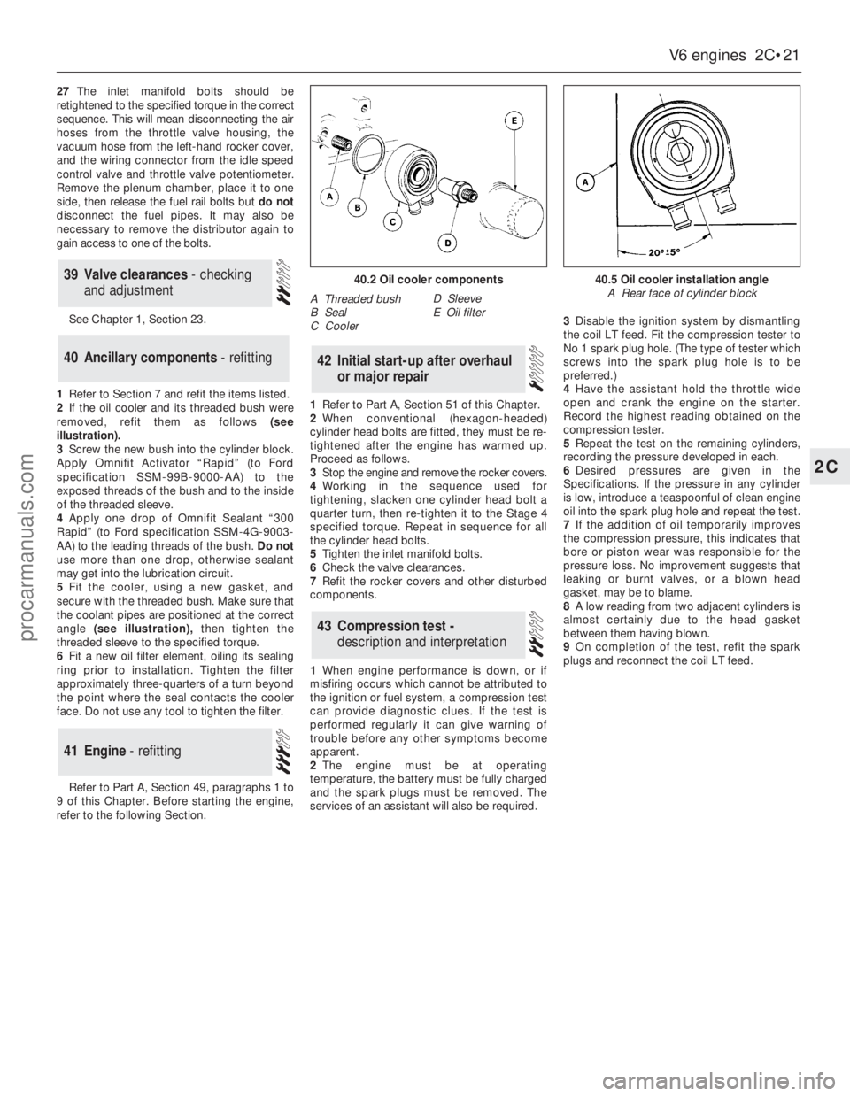
2If the oil cooler and its threaded bush were
removed, refit them as follows (see
illustration).
3Screw the new bush into the cylinder block.
Apply Omnifit Activator “Rapid” (to Ford
specification SSM-99B-9000-AA) to the
exposed threads of the bush and to the inside
of the threaded sleeve.
4Apply one drop of Omnifit Sealant “300
Rapid” (to Ford specification SSM-4G-9003-
AA) to the leading threads of the bush.Do not
use more than one drop, otherwise sealant
may get into the lubrication circuit.
5Fit the cooler, using a new gasket, and
secure with the threaded bush. Make sure that
the coolant pipes are positioned at the correct
angle (see illustration),then tighten the
threaded sleeve to the specified torque.
6Fit a new oil filter element, oiling its sealing
ring prior to installation. Tighten the filter
approximately three-quarters of a turn beyond
the point where the seal contacts the cooler
face. Do not use any tool to tighten the filter.
Refer to Part A, Section 49, paragraphs 1 to
9 of this Chapter. Before starting the engine,
refer to the following Section.1Refer to Part A, Section 51 of this Chapter.
2When conventional (hexagon-headed)
cylinder head bolts are fitted, they must be re-
tightened after the engine has warmed up.
Proceed as follows.
3Stop the engine and remove the rocker covers.
4Working in the sequence used for
tightening, slacken one cylinder head bolt a
quarter turn, then re-tighten it to the Stage 4
specified torque. Repeat in sequence for all
the cylinder head bolts.
5Tighten the inlet manifold bolts.
6Check the valve clearances.
7Refit the rocker covers and other disturbed
components.
1When engine performance is down, or if
misfiring occurs which cannot be attributed to
the ignition or fuel system, a compression test
can provide diagnostic clues. If the test is
performed regularly it can give warning of
trouble before any other symptoms become
apparent.
2The engine must be at operating
temperature, the battery must be fully charged
and the spark plugs must be removed. The
services of an assistant will also be required.3Disable the ignition system by dismantling
the coil LT feed. Fit the compression tester to
No 1 spark plug hole. (The type of tester which
screws into the spark plug hole is to be
preferred.)
4Have the assistant hold the throttle wide
open and crank the engine on the starter.
Record the highest reading obtained on the
compression tester.
5Repeat the test on the remaining cylinders,
recording the pressure developed in each.
6Desired pressures are given in the
Specifications. If the pressure in any cylinder
is low, introduce a teaspoonful of clean engine
oil into the spark plug hole and repeat the test.
7If the addition of oil temporarily improves
the compression pressure, this indicates that
bore or piston wear was responsible for the
pressure loss. No improvement suggests that
leaking or burnt valves, or a blown head
gasket, may be to blame.
8A low reading from two adjacent cylinders is
almost certainly due to the head gasket
between them having blown.
9On completion of the test, refit the spark
plugs and reconnect the coil LT feed.
43Compression test -
description and interpretation
42Initial start-up after overhaul
or major repair
41Engine - refitting
40Ancillary components - refitting
39Valve clearances - checking
and adjustment
V6 engines 2C•21
2C
40.2 Oil cooler components
A Threaded bush
B Seal
C CoolerD Sleeve
E Oil filter
40.5 Oil cooler installation angle
A Rear face of cylinder block
procarmanuals.com
Page 97 of 255
The exhaust system fitted in production is
made of aluminised steel, with stainless steel
used in the endplates and baffles of the rear
silencer. Individual sections of the system are
easily renewed in service.
Emission control for the UK market is
achieved largely by the inherent efficiency of
the fuel, ignition and engine management
systems. A welcome spin-off from such
efficiency is remarkably good fuel economy for
a vehicle of such size and weight.
Precautions
Fuel
Many of the procedures in this Chapter
require the removal of fuel lines and
connections which may result in some fuel
spillage. Residual pressure in fuel-injection
systems will remain in the fuel lines long after
the vehicle was last used, therefore extra care
must be taken when disconnecting a fuel line
hose. Loosen any fuel hose slowly to avoid a
sudden release of pressure which may cause
fuel spray. As an added precaution place a rag
over each union as it is disconnected to catch
any fuel which is forcibly expelled. Before
carrying out any operation on the fuel system
refer to the precautions given in “Safety first!”
at the beginning of this Manual and follow
them implicitly. Petrol is a highly dangerous
and volatile liquid and the precautions
necessary when handling it cannot be
overstressed
Tamperproof adjustment screws
Certain adjustment points in the fuel system
(and elsewhere) are protected by tamperproof
caps, plugs or seals. The purpose of such
tamperproofing is to discourage, and to deter,
adjustment by unqualified operators.
In some EU countries (though not yet in the
UK) it is an offence to drive a vehicle with
missing or broken tamperproof seals. Before
disturbing a tamperproof seal, satisfy yourself
that you will not be breaking local or national
anti-pollution regulations by doing so. Fit a
new seal when adjustment is complete when
this is required by law.
Do not break tamperproof seals on a vehicle
which is still under warranty.
Catalytic converter
The catalytic converter is a reliable and
simple device which needs no maintenance in
itself, but there are some facts of which an
owner should be aware if the converter is to
function properly for the full service life.
a)DO NOT use leaded petrol in a car
equipped with a catalytic converter the
lead will coat the precious metals,
reducing their converting efficiency and
will eventually destroy the converter.
b)Always keep the ignition and fuel systems
well-maintained in accordance with the
manufacturer’s schedule - particularly,
ensure that the air cleaner filter element,
the fuel filter and the spark plugs are
renewed at the correct interval - if the inletair/fuel mixture is allowed to become too
rich due to neglect, the unburned surplus
will enter and burn in the catalytic
converter, overheating the element and
eventually destroying the converter.
c)If the engine develops a misfire, do not
drive the car at all (or at least as little as
possible) until the fault is cured - the
misfire will allow unburned fuel to enter
the converter, which will result in
overheating, as noted above.
d)DO NOT push- or tow-start the car - this
will soak the catalytic converter in
unburned fuel, causing it to overheat when
the engine does start - see b) above.
e)DO NOT switch off the ignition at high
engine speeds - if the ignition is switched
off at anything above idle speed,
unburnedfuel will enter the (very hot)
catalytic converter, with the possible risk
of igniting on the element and damaging
the converter.
f)DO NOT use fuel or engine oil additives -
these may contain substances harmful to
the catalytic converter.
g)DO NOT continue to use the car if the
engine burns oil to the extent of leaving a
visible trail of blue smoke - the unburned
carbon deposits will clog the converter
passages and reduce the efficiency; in
severe cases the element will overheat.
h)Remember that the catalytic converter
operates at very high temperatures -
hence the heat shields on the car’s
underbody and the casing will become hot
enough to ignite combustible materials
which brush against it - DO NOT,
therefore, park the car in dry undergrowth,
over long grass or piles of dead leaves.
i)Remember that the catalytic converter is
FRAGILE, do not strike it with tools during
servicing work, take great care when
working on the exhaust system, ensure
that the converter is well clear of any jacks
or other lifting gear used to raise the car
and do not drive the car over rough
ground, road humps, etc, in such a way as
to “ground” the exhaust system.
j)In some cases, particularly when the car is
new and/or is used for stop/start driving, a
sulphurous smell (like that of rotten eggs)may be noticed from the exhaust. This is
common to many catalytic converter-
equipped cars and seems to be due to the
small amount of sulphur found in some
petrols reacting with hydrogen in the
exhaust to produce hydrogen sulphide
(H
2S) gas; while this gas is toxic, it is not
produced in sufficient amounts to be a
problem. Once the car has covered a few
thousand miles the problem should
disappear - in the meanwhile a change of
driving style or of the brand of petrol used
may effect a solution.
k)The catalytic converter, used on a well-
maintained and well-driven car, should
last for between 50 000 and 100 000 miles
- from this point on, careful checks should
be made at all specified service intervals
of the CO level to ensure that the
converter is still operating efficiently - if
the converter is no longer effective it must
be renewed.
See Chapter 1, Section 38.
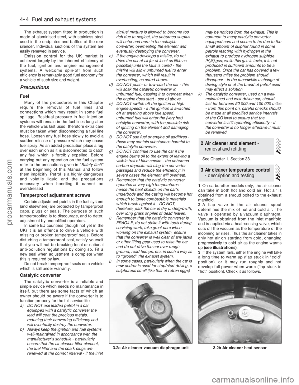
1On carburettor models only, the air cleaner
can take in both hot and cold air. Hot air is
obtained from a shroud bolted to the exhaust
manifold.
2A flap valve in the air cleaner spout
determines the mix of hot and cold air. The
valve is operated by a vacuum diaphragm.
Vacuum is obtained from the inlet manifold
and is applied via a heat-sensing valve, which
cuts off the vacuum as the temperature of the
incoming air rises. Thus the air cleaner takes in
only hot air on starting from cold, changing
progressively to cold air as the engine warms
up (see illustrations).
3If the system fails, either the engine will take
a long time to warm up (flap stuck in “cold”
position), or it may run roughly and not
develop full power when warm (flap stuck in
“hot” position). Check it as follows.
3Air cleaner temperature control
- description and testing
2Air cleaner and element -
removal and refitting
4•4Fuel and exhaust systems
3.2b Air cleaner heat sensor3.2a Air cleaner vacuum diaphragm unit
procarmanuals.com
Page 98 of 255
4With the engine cold, disconnect the cold
air inlet trunking from the spout. Look into the
spout and check that the flap valve is covering
the hot air inlet.
5Start the engine and allow it to idle. Check
that the flap moves to cover the cold air inlet. If
the flap does not move, check the diaphragm
and heat sensor as follows.
6Stop the engine. Disconnect the diaphragm
vacuum pipe from the heat sensor. Apply
vacuum to the diaphragm, using a vacuum
head pump or by connecting the pipe directly
to manifold vacuum. If the flap now moves, the
heat sensor or vacuum line was faulty. If the
flap still does not move, the diaphragm is
faulty or the flap is jammed.
7On completion reconnect the vacuum pipe
and the cold air trunking.
Mechanical
1Carburettor models without air conditioning
are fitted with a mechanical fuel pump, located
on the left-hand side of the engine block.
2To test the pump, disconnect the ignition
coil LT lead. Disconnect the outlet hose from
the pump and place a wad of rag next to the
pump outlet. Take appropriate fire
precautions.
3Have an assistant crank the engine on the
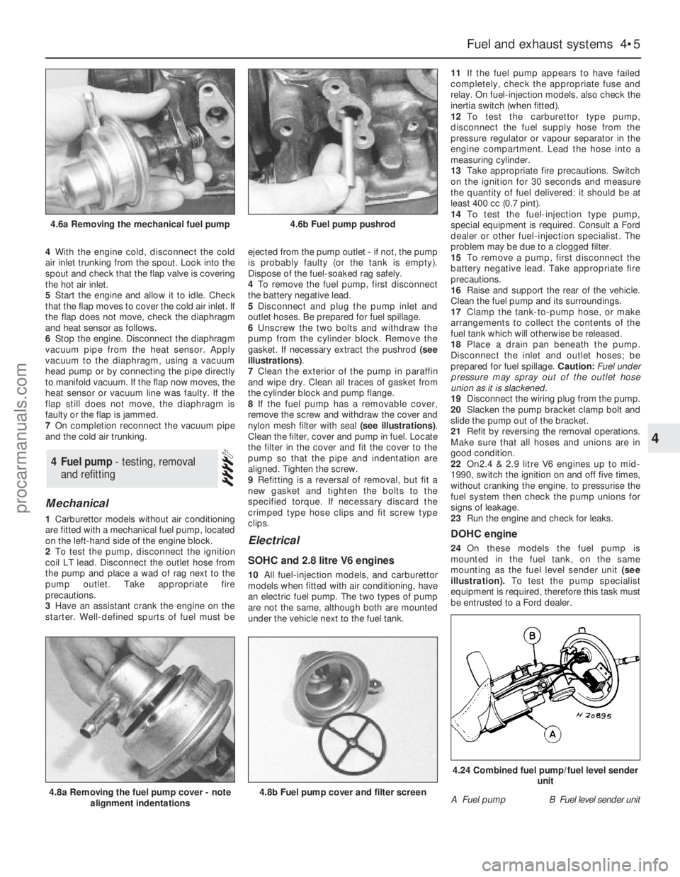
starter. Well-defined spurts of fuel must beejected from the pump outlet - if not, the pump
is probably faulty (or the tank is empty).
Dispose of the fuel-soaked rag safely.
4To remove the fuel pump, first disconnect
the battery negative lead.
5Disconnect and plug the pump inlet and
outlet hoses. Be prepared for fuel spillage.
6Unscrew the two bolts and withdraw the
pump from the cylinder block. Remove the
gasket. If necessary extract the pushrod (see
illustrations).
7Clean the exterior of the pump in paraffin
and wipe dry. Clean all traces of gasket from
the cylinder block and pump flange.
8If the fuel pump has a removable cover,
remove the screw and withdraw the cover and
nylon mesh filter with seal (see illustrations).
Clean the filter, cover and pump in fuel. Locate
the filter in the cover and fit the cover to the
pump so that the pipe and indentation are
aligned. Tighten the screw.
9Refitting is a reversal of removal, but fit a
new gasket and tighten the bolts to the
specified torque. If necessary discard the
crimped type hose clips and fit screw type
clips.
Electrical
SOHC and 2.8 litre V6 engines
10All fuel-injection models, and carburettor
models when fitted with air conditioning, have
an electric fuel pump. The two types of pump
are not the same, although both are mounted
under the vehicle next to the fuel tank.11If the fuel pump appears to have failed
completely, check the appropriate fuse and
relay. On fuel-injection models, also check the
inertia switch (when fitted).
12To test the carburettor type pump,
disconnect the fuel supply hose from the
pressure regulator or vapour separator in the
engine compartment. Lead the hose into a
measuring cylinder.
13Take appropriate fire precautions. Switch
on the ignition for 30 seconds and measure
the quantity of fuel delivered: it should be at
least 400 cc (0.7 pint).
14To test the fuel-injection type pump,
special equipment is required. Consult a Ford
dealer or other fuel-injection specialist. The
problem may be due to a clogged filter.
15To remove a pump, first disconnect the
battery negative lead. Take appropriate fire
precautions.
16Raise and support the rear of the vehicle.
Clean the fuel pump and its surroundings.
17Clamp the tank-to-pump hose, or make
arrangements to collect the contents of the
fuel tank which will otherwise be released.
18Place a drain pan beneath the pump.
Disconnect the inlet and outlet hoses; be
prepared for fuel spillage. Caution: Fuel under
pressure may spray out of the outlet hose
union as it is slackened.
19Disconnect the wiring plug from the pump.
20Slacken the pump bracket clamp bolt and
slide the pump out of the bracket.
21Refit by reversing the removal operations.
Make sure that all hoses and unions are in
good condition.
22On2.4 & 2.9 litre V6 engines up to mid-
1990, switch the ignition on and off five times,
without cranking the engine, to pressurise the
fuel system then check the pump unions for
signs of leakage.
23Run the engine and check for leaks.
DOHC engine
24On these models the fuel pump is
mounted in the fuel tank, on the same
mounting as the fuel level sender unit(see
illustration).To test the pump specialist
equipment is required, therefore this task must
be entrusted to a Ford dealer.
4Fuel pump - testing, removal
and refitting
Fuel and exhaust systems 4•5
4
4.6a Removing the mechanical fuel pump4.6b Fuel pump pushrod
4.8a Removing the fuel pump cover - note
alignment indentations4.8b Fuel pump cover and filter screenA Fuel pumpB Fuel level sender unit
4.24 Combined fuel pump/fuel level sender
unit
procarmanuals.com