1985 FORD GRANADA boot
[x] Cancel search: bootPage 3 of 255
1•2
Every 12 000 miles (20 000 km) or
12 months – whichever comes sooner
m mCheck operation of latches, check straps and locks; lubricate if
necessary (Section 19)
m mCheck condition and tension of auxiliary drivebelt(s); adjust or
renew as necessary (Section 21)
m mCheck tightness of battery terminals, clean and neutralise
corrosion if necessary (Section 22)
m mCheck engine valve clearances (Section 23) m
mCheck tightness of inlet manifold bolts (V6 only) (Section 24) m
mRenew spark plugs (Section 20) m
mClean air conditioning condenser fins (when applicable)
(Section 25)
m mCheck air conditioning refrigerant charge (when applicable)
(Section 26)
m mCheck manual gearbox oil level (Section 18) m
mCheck final drive oil level (Section 27) m
mLubricate automatic transmission selector/kickdown linkage
(Section 28)
m mCheck security and condition of steering and suspension
components, gaiters and boots (Section 29)
m mCheck condition and security of driveshaft joints (Section 30) m
mInspect underbody and panels for corrosion or other damage
(Section 31)
m mInspect brake pipes and hoses (Section 32) m
mClean idle speed control linkage at throttle (when applicable)
(Section 33)
m mRoad test and check operation of ABS (Section 34)m
mCheck automatic transmission fluid level (engine hot)
(Section 17)
m mCheck engine for satisfactory hot starting (Section 37)m
mCheck that automatic choke is fully off with engine hot (not fuel-
injection models) (Section 36)
m mCheck power steering fluid level (when applicable) (Section 35)
Every 24 000 miles (40 000 km) or
2 years - whichever comes sooner
m
mRenew air cleaner element (Section 38) m
mClean and inspect distributor cap, rotor arm, HT leads and coil
tower (Section 39)
m mAdjust automatic transmission brake bands (Section 40)m
mRenew fuel filter (fuel-injection models only) (Section 41) m
mRenew crankcase ventilation vent valve (carburettor models)
(Section 42)
Every 36 000 miles (60 000 km) or
3 years - whichever comes sooner
m
mRenew brake hydraulic system seals and hoses if necessary
(Section 43)
m mRenew brake hydraulic fluid (Section 44) m
mRenew camshaft drivebelt on SOHC models - recommended as
a precautionary measure (Section 45)
Every 2 years - regardless of mileage
m
mRenew coolant (Section 46)
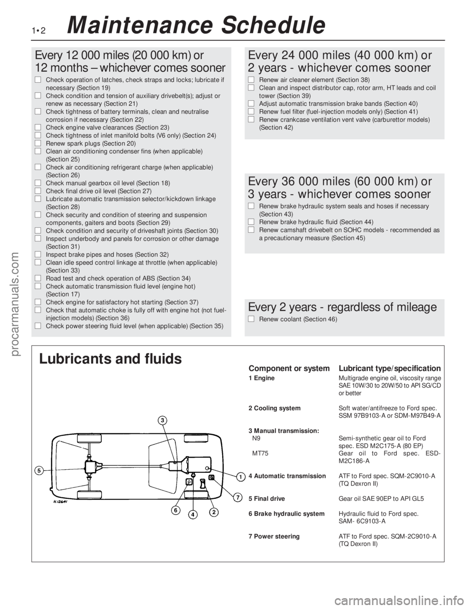
Lubricants and fluidsComponent or systemLubricant type/specification
1 EngineMultigrade engine oil, viscosity range
SAE 10W/30 to 20W/50 to API SG/CD
or better
2 Cooling systemSoft water/antifreeze to Ford spec.
SSM 97B9103-A or SDM-M97B49-A
3 Manual transmission:
N9Semi-synthetic gear oil to Ford
spec. ESD M2C175-A (80 EP)
MT75Gear oil to Ford spec. ESD-
M2C186-A
4 Automatic transmissionATF to Ford spec. SQM-2C9010-A
(TQ Dexron II)
5 Final driveGear oil SAE 90EP to APIGL5
6 Brake hydraulic systemHydraulic fluid to Ford spec.
SAM- 6C9103-A
7 Power steeringATFto Ford spec. SQM-2C9010-A
(TQDexron II)
Maintenance Schedule
procarmanuals.com
Page 134 of 255
1It is necessary to remove the rear wheels in
order to inspect the rear pads. The pads can
be viewed through the top of the caliper after
removing the spring clip. If any one pad is
worn down to the minimum specified, all four
pads (on both rear wheels) must be renewed.
2Free the handbrake cable from its clip on
the suspension lower arm. Release the
handbrake.
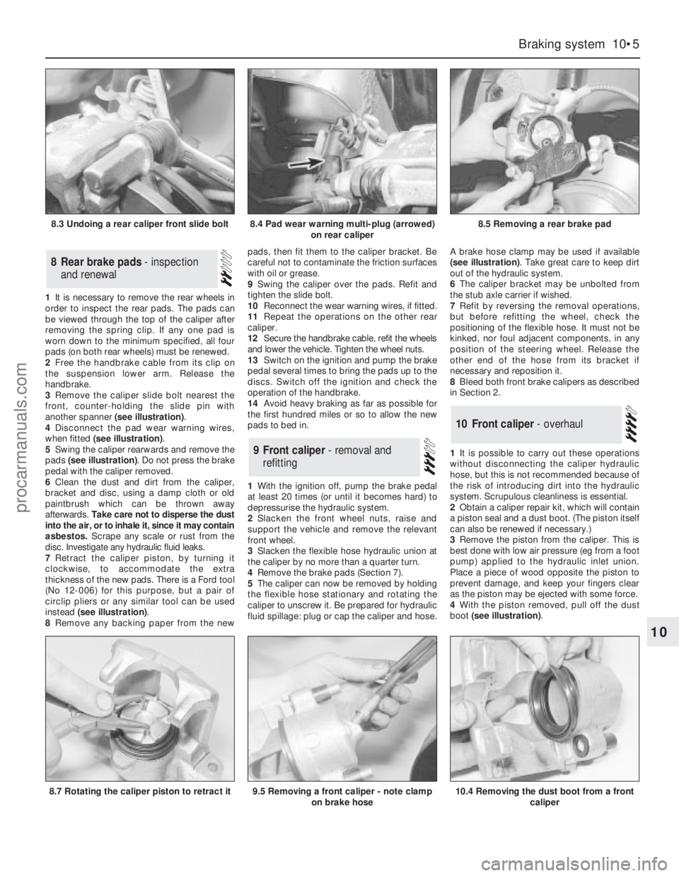
3Remove the caliper slide bolt nearest the
front, counter-holding the slide pin with
another spanner (see illustration).
4Disconnect the pad wear warning wires,
when fitted (see illustration).
5Swing the caliper rearwards and remove the
pads (see illustration). Do not press the brake
pedal with the caliper removed.
6Clean the dust and dirt from the caliper,
bracket and disc, using a damp cloth or old
paintbrush which can be thrown away
afterwards. Take care not to disperse the dust
into the air, or to inhale it, since it may contain
asbestos. Scrape any scale or rust from the
disc. Investigate any hydraulic fluid leaks.
7Retract the caliper piston, by turning it
clockwise, to accommodate the extra
thickness of the new pads. There is a Ford tool
(No 12-006) for this purpose, but a pair of
circlip pliers or any similar tool can be used
instead (see illustration).
8Remove any backing paper from the newpads, then fit them to the caliper bracket. Be
careful not to contaminate the friction surfaces
with oil or grease.
9Swing the caliper over the pads. Refit and
tighten the slide bolt.
10Reconnect the wear warning wires, if fitted.
11Repeat the operations on the other rear
caliper.
12Secure the handbrake cable, refit the wheels
and lower the vehicle. Tighten the wheel nuts.
13Switch on the ignition and pump the brake
pedal several times to bring the pads up to the
discs. Switch off the ignition and check the
operation of the handbrake.
14Avoid heavy braking as far as possible for
the first hundred miles or so to allow the new
pads to bed in.
1With the ignition off, pump the brake pedal
at least 20 times (or until it becomes hard) to
depressurise the hydraulic system.
2Slacken the front wheel nuts, raise and
support the vehicle and remove the relevant
front wheel.
3Slacken the flexible hose hydraulic union at
the caliper by no more than a quarter turn.
4Remove the brake pads (Section 7).
5The caliper can now be removed by holding
the flexible hose stationary and rotating the
caliper to unscrew it. Be prepared for hydraulic
fluid spillage: plug or cap the caliper and hose.A brake hose clamp may be used if available
(see illustration). Take great care to keep dirt
out of the hydraulic system.
6The caliper bracket may be unbolted from
the stub axle carrier if wished.
7Refit by reversing the removal operations,
but before refitting the wheel, check the
positioning of the flexible hose. It must not be
kinked, nor foul adjacent components, in any
position of the steering wheel. Release the
other end of the hose from its bracket if
necessary and reposition it.
8Bleed both front brake calipers as described
in Section 2.
1It is possible to carry out these operations
without disconnecting the caliper hydraulic
hose, but this is not recommended because of
the risk of introducing dirt into the hydraulic
system. Scrupulous cleanliness is essential.
2Obtain a caliper repair kit, which will contain
a piston seal and a dust boot. (The piston itself
can also be renewed if necessary.)
3Remove the piston from the caliper. This is
best done with low air pressure (eg from a foot
pump) applied to the hydraulic inlet union.
Place a piece of wood opposite the piston to
prevent damage, and keep your fingers clear
as the piston may be ejected with some force.
4With the piston removed, pull off the dust
boot (see illustration).
10Front caliper - overhaul
9Front caliper - removal and
refitting
8Rear brake pads - inspection
and renewal
Braking system 10•5
10
8.3 Undoing a rear caliper front slide bolt8.4 Pad wear warning multi-plug (arrowed)
on rear caliper8.5 Removing a rear brake pad
8.7 Rotating the caliper piston to retract it9.5 Removing a front caliper - note clamp
on brake hose10.4 Removing the dust boot from a front
caliper
procarmanuals.com
Page 135 of 255
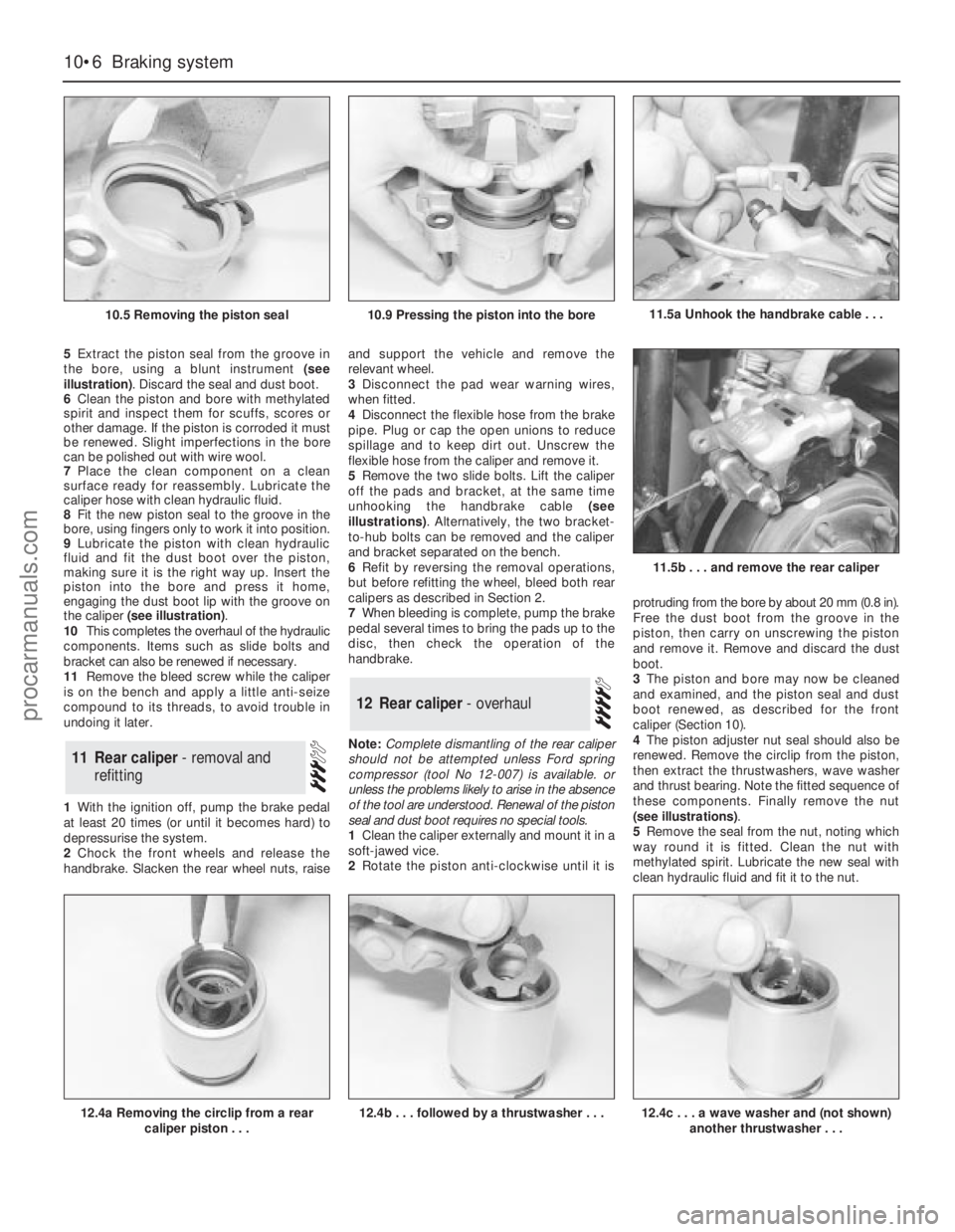
5Extract the piston seal from the groove in
the bore, using a blunt instrument (see
illustration). Discard the seal and dust boot.
6Clean the piston and bore with methylated
spirit and inspect them for scuffs, scores or
other damage. If the piston is corroded it must
be renewed. Slight imperfections in the bore
can be polished out with wire wool.
7Place the clean component on a clean
surface ready for reassembly. Lubricate the
caliper hose with clean hydraulic fluid.
8Fit the new piston seal to the groove in the
bore, using fingers only to work it into position.
9Lubricate the piston with clean hydraulic
fluid and fit the dust boot over the piston,
making sure it is the right way up. Insert the
piston into the bore and press it home,
engaging the dust boot lip with the groove on
the caliper (see illustration).
10This completes the overhaul of the hydraulic
components. Items such as slide bolts and
bracket can also be renewed if necessary.
11Remove the bleed screw while the caliper
is on the bench and apply a little anti-seize
compound to its threads, to avoid trouble in
undoing it later.
1With the ignition off, pump the brake pedal
at least 20 times (or until it becomes hard) to
depressurise the system.
2Chock the front wheels and release the
handbrake. Slacken the rear wheel nuts, raiseand support the vehicle and remove the
relevant wheel.
3Disconnect the pad wear warning wires,
when fitted.
4Disconnect the flexible hose from the brake
pipe. Plug or cap the open unions to reduce
spillage and to keep dirt out. Unscrew the
flexible hose from the caliper and remove it.
5Remove the two slide bolts. Lift the caliper
off the pads and bracket, at the same time
unhooking the handbrake cable (see
illustrations). Alternatively, the two bracket-
to-hub bolts can be removed and the caliper
and bracket separated on the bench.
6Refit by reversing the removal operations,
but before refitting the wheel, bleed both rear
calipers as described in Section 2.
7When bleeding is complete, pump the brake
pedal several times to bring the pads up to the
disc, then check the operation of the
handbrake.
Note: Complete dismantling of the rear caliper
should not be attempted unless Ford spring
compressor (tool No 12-007) is available. or
unless the problems likely to arise in the absence
of the tool are understood. Renewal of the piston
seal and dust boot requires no special tools.
1Clean the caliper externally and mount it in a
soft-jawed vice.
2Rotate the piston anti-clockwise until it isprotruding from the bore by about 20 mm (0.8 in).
Free the dust boot from the groove in the
piston, then carry on unscrewing the piston
and remove it. Remove and discard the dust
boot.
3The piston and bore may now be cleaned
and examined, and the piston seal and dust
boot renewed, as described for the front
caliper (Section 10).
4The piston adjuster nut seal should also be
renewed. Remove the circlip from the piston,
then extract the thrustwashers, wave washer
and thrust bearing. Note the fitted sequence of
these components. Finally remove the nut
(see illustrations).
5Remove the seal from the nut, noting which
way round it is fitted. Clean the nut with
methylated spirit. Lubricate the new seal with
clean hydraulic fluid and fit it to the nut.
12Rear caliper - overhaul
11Rear caliper - removal and
refitting
10•6Braking system
10.5 Removing the piston seal
12.4a Removing the circlip from a rear
caliper piston . . .12.4b . . . followed by a thrustwasher . . .
11.5b . . . and remove the rear caliper
10.9 Pressing the piston into the bore11.5a Unhook the handbrake cable . . .
12.4c . . . a wave washer and (not shown)
another thrustwasher . . .
procarmanuals.com
Page 137 of 255
17Refit the washer, spring and spring cover.
Compress the spring and refit the circlip, then
release the spring compressor.
18Lubricate the caliper bore with clean
hydraulic fluid and fit a new piston seal.
19Reassemble the piston components.
Lubricate the contact face of the adjuster nut
with a little brake grease, then fit the adjuster
nut (with new seal), thrust bearing,
thrustwasher, wave washer and the second
thrustwasher. Secure with the circlip.
20Fit a new dust boot. The manufacturers
recommend that it be fitted to the caliper
groove and the piston fitted afterwards; it is
also possible to fit the boot to the piston first
and engage it in the caliper groove afterwards.
Either way it is a fiddly business.
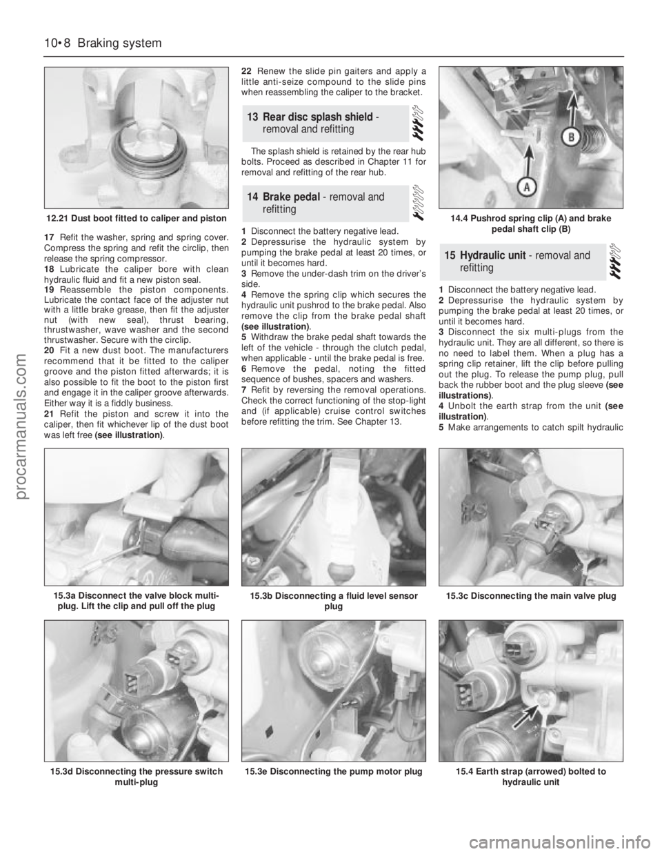
21Refit the piston and screw it into the
caliper, then fit whichever lip of the dust boot
was left free (see illustration).22Renew the slide pin gaiters and apply a
little anti-seize compound to the slide pins
when reassembling the caliper to the bracket.
The splash shield is retained by the rear hub
bolts. Proceed as described in Chapter 11 for
removal and refitting of the rear hub.
1Disconnect the battery negative lead.
2Depressurise the hydraulic system by
pumping the brake pedal at least 20 times, or
until it becomes hard.
3Remove the under-dash trim on the driver’s
side.
4Remove the spring clip which secures the
hydraulic unit pushrod to the brake pedal. Also
remove the clip from the brake pedal shaft
(see illustration).
5Withdraw the brake pedal shaft towards the
left of the vehicle - through the clutch pedal,
when applicable - until the brake pedal is free.
6Remove the pedal, noting the fitted
sequence of bushes, spacers and washers.
7Refit by reversing the removal operations.
Check the correct functioning of the stop-light
and (if applicable) cruise control switches
before refitting the trim. See Chapter 13.1Disconnect the battery negative lead.
2Depressurise the hydraulic system by
pumping the brake pedal at least 20 times, or
until it becomes hard.
3Disconnect the six multi-plugs from the
hydraulic unit. They are all different, so there is
no need to label them. When a plug has a
spring clip retainer, lift the clip before pulling
out the plug. To release the pump plug, pull
back the rubber boot and the plug sleeve (see
illustrations).
4Unbolt the earth strap from the unit (see
illustration).
5Make arrangements to catch spilt hydraulic
15Hydraulic unit - removal and
refitting
14Brake pedal - removal and
refitting
13Rear disc splash shield -
removal and refitting
10•8Braking system
12.21 Dust boot fitted to caliper and piston
15.3d Disconnecting the pressure switch
multi-plug15.3e Disconnecting the pump motor plug15.4 Earth strap (arrowed) bolted to
hydraulic unit
14.4 Pushrod spring clip (A) and brake
pedal shaft clip (B)
15.3a Disconnect the valve block multi-
plug. Lift the clip and pull off the plug15.3b Disconnecting a fluid level sensor
plug15.3c Disconnecting the main valve plug
procarmanuals.com
Page 140 of 255
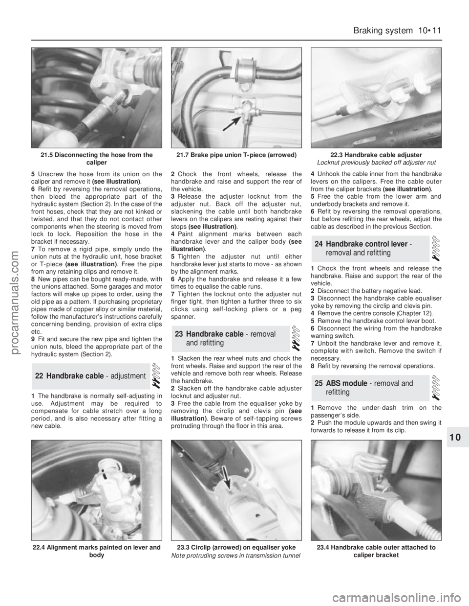
5Unscrew the hose from its union on the
caliper and remove it (see illustration).
6Refit by reversing the removal operations,
then bleed the appropriate part of the
hydraulic system (Section 2). In the case of the
front hoses, check that they are not kinked or
twisted, and that they do not contact other
components when the steering is moved from
lock to lock. Reposition the hose in the
bracket if necessary.
7To remove a rigid pipe, simply undo the
union nuts at the hydraulic unit, hose bracket
or T-piece (see illustration). Free the pipe
from any retaining clips and remove it.
8New pipes can be bought ready-made, with
the unions attached. Some garages and motor
factors will make up pipes to order, using the
old pipe as a pattern. If purchasing proprietary
pipes made of copper alloy or similar material,
follow the manufacturer’s instructions carefully
concerning bending, provision of extra clips
etc.
9Fit and secure the new pipe and tighten the
union nuts, bleed the appropriate part of the
hydraulic system (Section 2).
1The handbrake is normally self-adjusting in
use. Adjustment may be required to
compensate for cable stretch over a long
period, and is also necessary after fitting a
new cable.2Chock the front wheels, release the
handbrake and raise and support the rear of
the vehicle.
3Release the adjuster locknut from the
adjuster nut. Back off the adjuster nut,
slackening the cable until both handbrake
levers on the calipers are resting against their
stops (see illustration).
4Paint alignment marks between each
handbrake lever and the caliper body (see
illustration).
5Tighten the adjuster nut until either
handbrake lever just starts to move - as shown
by the alignment marks.
6Apply the handbrake and release it a few
times to equalise the cable runs.
7Tighten the locknut onto the adjuster nut
finger tight, then tighten a further three to six
clicks using self-locking pliers or a peg
spanner.
1Slacken the rear wheel nuts and chock the
front wheels. Raise and support the rear of the
vehicle and remove both rear wheels. Release
the handbrake.
2Slacken off the handbrake cable adjuster
locknut and adjuster nut.
3Free the cable from the equaliser yoke by
removing the circlip and clevis pin (see
illustration). Beware of self-tapping screws
protruding through the floor in this area.4Unhook the cable inner from the handbrake
levers on the calipers. Free the cable outer
from the caliper brackets (see illustration).
5Free the cable from the lower arm and
underbody brackets and remove it.
6Refit by reversing the removal operations,
but before refitting the rear wheels, adjust the
cable as described in the previous Section.
1Chock the front wheels and release the
handbrake. Raise and support the rear of the
vehicle.
2Disconnect the battery negative lead.
3Disconnect the handbrake cable equaliser
yoke by removing the circlip and clevis pin.
4Remove the centre console (Chapter 12).
5Remove the handbrake control lever boot.
6Disconnect the wiring from the handbrake
warning switch.
7Unbolt the handbrake lever and remove it,
complete with switch. Remove the switch if
necessary.
8Refit by reversing the removal operations.
1Remove the under-dash trim on the
passenger’s side.
2Push the module upwards and then swing it
forwards to release it from its clip.
25ABS module - removal and
refitting
24Handbrake control lever -
removal and refitting
23Handbrake cable - removal
and refitting
22Handbrake cable - adjustment
Braking system 10•11
10
21.5 Disconnecting the hose from the
caliper21.7 Brake pipe union T-piece (arrowed)22.3 Handbrake cable adjuster
Locknut previously backed off adjuster nut
22.4 Alignment marks painted on lever and
body23.3 Circlip (arrowed) on equaliser yoke
Note protruding screws in transmission tunnel23.4 Handbrake cable outer attached to
caliper bracket
procarmanuals.com
Page 152 of 255
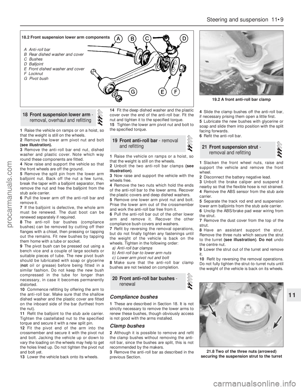
1Raise the vehicle on ramps or on a hoist, so
that the weight is still on the wheels.
2Remove the lower arm pivot nut and bolt
(see illustration).
3Remove the anti-roll bar end nut, dished
washer and plastic cover. Note which way
round these components are fitted.
4Now raise and support the vehicle so that
the front wheels are off the ground.
5Remove the split pin from the lower arm
balljoint nut. Back off the nut a few turns,
break the taper with a balljoint separator, then
remove the nut and free the balljoint from the
stub axle carrier.
6Pull the lower arm off the anti-roll bar and
remove it.
7If the balljoint is defective, the whole arm
must be renewed. The dust boot can be
renewed separately if required.
8The anti-roll bar bushes (compliance
bushes) can be removed by cutting off their
flanges with a chisel, then pressing or tapping
out the remains. Fit new bushes by tapping
them home with a tube or socket.
9The pivot bush can be pressed out using a
bench vice and a couple of large sockets or
suitable pieces of tube. The new pivot bush
should be lubricated with soap or glycerine
(notoil or grease) before being fitted in a
similar fashion. Do not keep the new bush
compressed in the tube for longer than
necessary, in case it becomes permanently
distorted.
10Commence refitting by offering the arm to
the anti-roll bar. Make sure that the shallow
dished washer and the plastic cover are fitted
on the inboard side of the bar (furthest from
the nut).
11Refit the balljoint to the stub axle carrier.
Tighten the castellated nut to the specified
torque and secure it with a new split pin.
12Fit the pivot end of the arm into the
crossmember and secure it with the pivot nut
and bolt. Jacking the vehicle up or down to
vary the loading on the wheels may help to get
the holes lined up. Do not tighten the pivot nut
and bolt yet.
13Lower the vehicle back onto its wheels.14Fit the deep dished washer and the plastic
cover over the end of the anti-roll bar. Fit the
nut and tighten it to the specified torque.
15Tighten the lower arm pivot nut and bolt to
the specified torque.
1Raise the vehicle on ramps or a hoist, so
that the weight is still on the wheels.
2Unbolt the two anti-roll bar clamps (see
illustration).
3Now raise and support the vehicle with the
wheels free.
4Remove the two nuts which hold the ends
of the anti-roll bar to the lower arms. Recover
the plastic covers and deep dished washers.
5Remove one lower arm pivot nut and bolt.
Prise the lower arm out of the crossmember
and work the anti-roll bar free from it.
6Pull the anti-roll bar out of the other lower
arm and remove it. Recover the other
compliance bush covers and washers.
7Refit by reversing the removal operations,
but do not finally tighten any fastenings until
the weight of the vehicle is back on the
wheels. Tighten in the following order:
a)Anti-roll bar clamps
b)Anti-roll bar-to lower arm nuts
c)Lower arm pivot nut and bolt
8Make sure that the anti-roll bar clamp
bushes are not twisted on completion.
Compliance bushes
1These are described in Section 18. It is not
strictly necessary to remove the lower arms to
renew these bushes, though obviously access
is not good with the arms installed.
Clamp bushes
2Although it is possible to remove and refit
the clamp bushes without removing the anti-
roll bar, since the bushes are split, this is not
recommended by the makers.
3Remove the anti-roll bar as described in the
previous Section.4Slide the clamp bushes off the anti-roll bar,
if necessary prising them open a little first.
5Lubricate the new bushes with glycerine or
soap and slide them into position with the split
facing forwards.
6Refit the anti-roll bar.
1Slacken the front wheel nuts, raise and
support the vehicle and remove the front
wheel.
2Disconnect the battery negative lead.
3Unbolt the brake caliper and suspend it
nearby so that the flexible hose is not strained.
4Remove the ABS sensor from the stub axle
carrier.
5Separate the track rod end and suspension
lower arm balljoints from the stub axle carrier.
6Unclip the ABS/brake pad wear wiring from
the strut.
7Remove the dust cover from the top of the
strut.
8Have an assistant support the strut.
Remove the three nuts which secure the strut
to the turret (see illustration).Do notundo
the centre nut.
9Lower the strut out of the turret and remove
it.
10Refit by reversing the removal operations.
Do not fully tighten the strut-to-turret nuts until
the weight of the vehicle is back on its wheels.
21Front suspension strut -
removal and refitting
20Front anti-roll bar bushes -
renewal
19Front anti-roll bar - removal
and refitting
18Front suspension lower arm -
removal, overhaul and refitting
Steering and suspension 11•9
11
19.2 A front anti-roll bar clamp
21.8 Two of the three nuts (arrowed)
securing the suspension strut to the turret
18.2 Front suspension lower arm components
A Anti-roll bar
B Rear dished washer and cover
C Bushes
D Balljoint
E Front dished washer and cover
F Locknut
G Pivot bush
procarmanuals.com
Page 158 of 255
Chapter 12
Bodywork and fittings
Bonnet - removal and refitting . . . . . . . . . . . . . . . . . . . . . . . . . . . . . .6
Bonnet insulation panel - removal and refitting . . . . . . . . . . . . . . . .26
Bonnet release cable - removal and refitting . . . . . . . . . . . . . . . . . .11
Boot lid lock barrel - removal and refitting . . . . . . . . . . . . . . . . . . . .18
Boot lid - removal, refitting and adjustment . . . . . . . . . . . . . . . . . . . .9
Bumper mouldings - removal and refitting . . . . . . . . . . . . . . . . . . . .36
Bumpers - removal and refitting . . . . . . . . . . . . . . . . . . . . . . . . . . . .35
Centre console - removal and refitting . . . . . . . . . . . . . . . . . . . . . . .42
Door - removal and refitting . . . . . . . . . . . . . . . . . . . . . . . . . . . . . . . .7
Door exterior handle - removal and refitting . . . . . . . . . . . . . . . . . .13
Door interior trim panel - removal and refitting . . . . . . . . . . . . . . . .22
Door latch assembly - removal and refitting . . . . . . . . . . . . . . . . . .15
Door lock barrel - removal and refitting . . . . . . . . . . . . . . . . . . . . . .14
Door striker plate - adjustment . . . . . . . . . . . . . . . . . . . . . . . . . . . . .12
Door weatherstrip - removal and refitting . . . . . . . . . . . . . . . . . . . .16
Door window frame mouldings - removal and refitting . . . . . . . . . .31
Door window glass - removal and refitting . . . . . . . . . . . . . . . . . . . .23
Door window regulator mechanism - removal and refitting . . . . . . .24
Exterior mirror - removal and refitting . . . . . . . . . . . . . . . . . . . . . . .39
Facia panels and trim - removal and refitting . . . . . . . . . . . . . . . . . .41
Front bumper - height adjustment . . . . . . . . . . . . . . . . . . . . . . . . . .34
Front seat - removal and refitting . . . . . . . . . . . . . . . . . . . . . . . . . . .44
Front seat air cushion - removal and refitting . . . . . . . . . . . . . . . . .45
Front seat belts - removal and refitting . . . . . . . . . . . . . . . . . . . . . .47
Front spoiler - removal and refitting . . . . . . . . . . . . . . . . . . . . . . . . .37Fuel filler lock barrel - removal and refitting . . . . . . . . . . . . . . . . . . .21
General information . . . . . . . . . . . . . . . . . . . . . . . . . . . . . . . . . . . . . .1
Headlining - removal and refitting . . . . . . . . . . . . . . . . . . . . . . . . . .38
Interior mirror - removal and refitting . . . . . . . . . . . . . . . . . . . . . . . .40
Maintenance - bodywork and underframe . . . . . . . . . . . . . . . . . . . . .2
Maintenance - upholstery and carpets . . . . . . . . . . . . . . . . . . . . . . . .3
Major body damage - repair . . . . . . . . . . . . . . . . . . . . . . . . . . . . . . . .5
Minor body damage - repair . . . . . . . . . . . . . . . . . . . . . . . . . . . . . . . .4
Motifs and emblems - removal and refitting . . . . . . . . . . . . . . . . . .33
Overhead console - removal and refitting . . . . . . . . . . . . . . . . . . . .43
Radiator grille - removal and refitting . . . . . . . . . . . . . . . . . . . . . . . .27
Rear parcel shelf - removal and refitting . . . . . . . . . . . . . . . . . . . . .50
Rear quarter window moulding - removal and refitting . . . . . . . . . .32
Rear seat belts - removal and refitting . . . . . . . . . . . . . . . . . . . . . . .48
Rear seat components - removal and refitting . . . . . . . . . . . . . . . . .49
Seat belts - care and maintenance . . . . . . . . . . . . . . . . . . . . . . . . .46
Side mouldings - removal and refitting . . . . . . . . . . . . . . . . . . . . . .28
Sliding roof - removal and refitting . . . . . . . . . . . . . . . . . . . . . . . . . .10
Tailgate - removal and refitting . . . . . . . . . . . . . . . . . . . . . . . . . . . . . .8
Tailgate latch assembly - removal and refitting . . . . . . . . . . . . . . . .19
Tailgate lock barrel - removal and refitting . . . . . . . . . . . . . . . . . . . .17
Tailgate strut - removal and refitting . . . . . . . . . . . . . . . . . . . . . . . .20
Tailgate window mouldings - removal and refitting . . . . . . . . . . . . .30
Windscreen and fixed glass - removal and refitting . . . . . . . . . . . . .25
Windscreen mouldings - removal and refitting . . . . . . . . . . . . . . . .29
Torque wrench settingsNm lbf ft
Front seat belt buckle to seat frame . . . . . . . . . . . . . . . . . . . . . . . . . . . . 51 to 64 38 to 47
Seat belt retractor bolts (front and rear) . . . . . . . . . . . . . . . . . . . . . . . . . 25 to 45 18 to 33
Other seat belt anchorages . . . . . . . . . . . . . . . . . . . . . . . . . . . . . . . . . . 25 to 45 18 to 33
Rear seat back hinge to body . . . . . . . . . . . . . . . . . . . . . . . . . . . . . . . . . 21 to 25 16 to 18
Rear seat back latch striker . . . . . . . . . . . . . . . . . . . . . . . . . . . . . . . . . . 40 to 60 30 to 44
Front seat retaining bolts . . . . . . . . . . . . . . . . . . . . . . . . . . . . . . . . . . . . 25 to 32 18 to 24
Front seat frame-to-slide bolts . . . . . . . . . . . . . . . . . . . . . . . . . . . . . . . . 25 to 32 18 to 24
Rear bumper mountings . . . . . . . . . . . . . . . . . . . . . . . . . . . . . . . . . . . . . 21 16
Front bumper adjuster lockbolt . . . . . . . . . . . . . . . . . . . . . . . . . . . . . . . 21 16
12•1
Easy,suitable for
novice with little
experienceFairly easy,suitable
for beginner with
some experienceFairly difficult,
suitable for competent
DIY mechanicDifficult,suitable for
experienced DIY
mechanicVery difficult,
suitable for expert
DIY or professional
Degrees of difficulty
Specifications Contents
12
The bodyshell and floorpan are of pressed
steel, and form an integral part of the vehicle’s
structure. Various reinforcing and mounting
components beneath the floorpan are made of
HSLA (High Strength Low Alloy) and REPHOS
(rephosphorised) steels, which have superiorstrength-to-weight characteristics when
compared with conventional steels.
Extensive use is made of plastic for
peripheral components such as the radiator
grille, bumpers and wheel trims, and for much
of the interior trim.
Interior fittings are to the high standard
expected in a vehicle of this class, with even
the basic level models well equipped. A wide
range of options is available, including air
conditioning and leather upholstery.The general condition of a vehicle’s
bodywork is the one thing that significantly
affects its value. Maintenance is easy, but
needs to be regular. Neglect, particularly after
minor damage, can lead quickly to further
deterioration and costly repair bills. It is
2 Maintenance - bodywork and
underframe1 General information
procarmanuals.com
Page 162 of 255
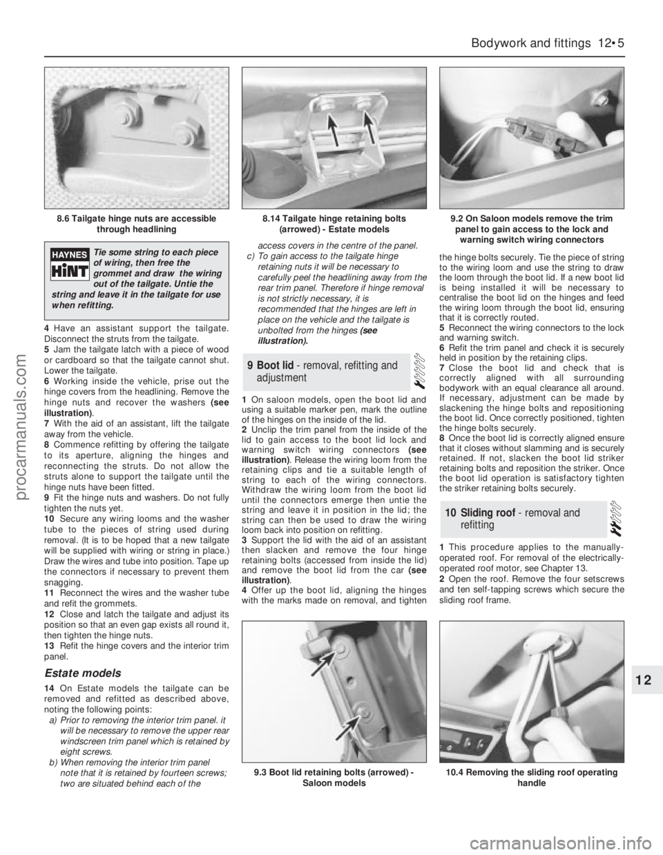
4Have an assistant support the tailgate.
Disconnect the struts from the tailgate.
5Jam the tailgate latch with a piece of wood
or cardboard so that the tailgate cannot shut.
Lower the tailgate.
6Working inside the vehicle, prise out the
hinge covers from the headlining. Remove the
hinge nuts and recover the washers (see
illustration).
7With the aid of an assistant, lift the tailgate
away from the vehicle.
8Commence refitting by offering the tailgate
to its aperture, aligning the hinges and
reconnecting the struts. Do not allow the
struts alone to support the tailgate until the
hinge nuts have been fitted.
9Fit the hinge nuts and washers. Do not fully
tighten the nuts yet.
10Secure any wiring looms and the washer
tube to the pieces of string used during
removal. (It is to be hoped that a new tailgate
will be supplied with wiring or string in place.)
Draw the wires and tube into position. Tape up
the connectors if necessary to prevent them
snagging.
11Reconnect the wires and the washer tube
and refit the grommets.
12Close and latch the tailgate and adjust its
position so that an even gap exists all round it,
then tighten the hinge nuts.
13Refit the hinge covers and the interior trim
panel.
Estate models
14On Estate models the tailgate can be
removed and refitted as described above,
noting the following points:
a)Prior to removing the interior trim panel. it
will be necessary to remove the upper rear
windscreen trim panel which is retained by
eight screws.
b)When removing the interior trim panel
note that it is retained by fourteen screws;
two are situated behind each of theaccess covers in the centre of the panel.
c)To gain access to the tailgate hinge
retaining nuts it will be necessary to
carefully peelthe headlining away from the
rear trim panel. Therefore if hinge removal
is not strictly necessary, it is
recommended that the hinges are left in
place on the vehicle and the tailgate is
unbolted from the hinges (see
illustration).
1On saloon models, open the boot lid and
using a suitable marker pen, mark the outline
of the hinges on the inside of the lid.
2Unclip the trim panel from the inside of the
lid to gain access to the boot lid lock and
warning switch wiring connectors (see
illustration). Release the wiring loom from the
retaining clips and tie a suitable length of
string to each of the wiring connectors.
Withdraw the wiring loom from the boot lid
until the connectors emerge then untie the
string and leave it in position in the lid; the
string can then be used to draw the wiring
loom back into position on refitting.
3Support the lid with the aid of an assistant
then slacken and remove the four hinge
retaining bolts (accessed from inside the lid)
and remove the boot lid from the car (see
illustration).
4Offer up the boot lid, aligning the hinges
with the marks made on removal, and tightenthe hinge bolts securely. Tie the piece of string
to the wiring loom and use the string to draw
the loom through the boot lid. If a new boot lid
is being installed it will be necessary to
centralise the boot lid on the hinges and feed
the wiring loom through the boot lid, ensuring
that it is correctly routed.
5Reconnect the wiring connectors to the lock
and warning switch.
6Refit the trim panel and check it is securely
held in position by the retaining clips.
7Close the boot lid and check that is
correctly aligned with all surrounding
bodywork with an equal clearance all around.
If necessary, adjustment can be made by
slackening the hinge bolts and repositioning
the boot lid. Once correctly positioned, tighten
the hinge bolts securely.
8Once the boot lid is correctly aligned ensure
that it closes without slamming and is securely
retained. If not, slacken the boot lid striker
retaining bolts and reposition the striker. Once
the boot lid operation is satisfactory tighten
the striker retaining bolts securely.
1This procedure applies to the manually-
operated roof. For removal of the electrically-
operated roof motor, see Chapter 13.
2Open the roof. Remove the four setscrews
and ten self-tapping screws which secure the
sliding roof frame.
10Sliding roof - removal and
refitting
9Boot lid - removal, refitting and
adjustment
Bodywork and fittings 12•5
12
8.6 Tailgate hinge nuts are accessible
through headlining8.14 Tailgate hinge retaining bolts
(arrowed) - Estate models9.2 On Saloon models remove the trim
panel to gain access to the lock and
warning switch wiring connectors
9.3 Boot lid retaining bolts (arrowed) -
Saloon models10.4 Removing the sliding roof operating
handle
Tie some string to each piece
of wiring, then free the
grommet and draw the wiring
out of the tailgate. Untie the
string and leave it in the tailgate for use
when refitting.
procarmanuals.com