1985 FORD GRANADA driver seat adjustment
[x] Cancel search: driver seat adjustmentPage 102 of 255

1Check the cost and availability of spare parts
before deciding to dismantle the carburettor. If
the unit has seen much service, fitting a new or
reconditioned carburettor may prove more
satisfactory than any attempt at overhaul.
2Obtain a carburettor repair kit, which will
contain the necessary gaskets, diaphragms
and other renewable items.
3With the carburettor removed from the
vehicle, clean it thoroughly externally and
place it on a clean worksurface.
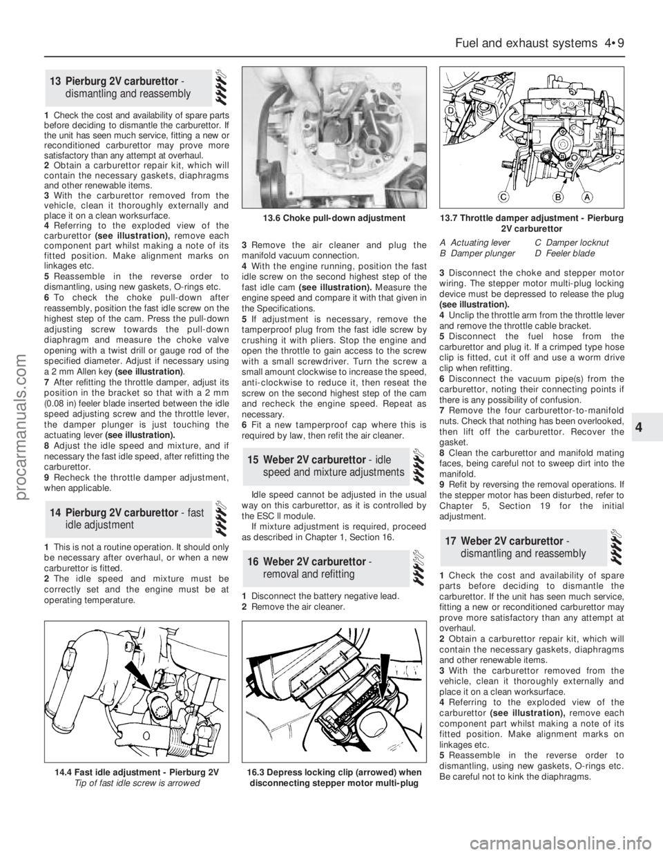
4 Referringto the exploded view of the
carburettor(see illustration),remove each
component part whilst making a note of its
fitted position. Make alignment marks on
linkages etc.
5Reassemble in the reverse order to
dismantling, using new gaskets, O-rings etc.
6To check the choke pull-down after
reassembly, position the fast idle screw on the
highest step of the cam. Press the pull-down
adjusting screw towards the pull-down
diaphragm and measure the choke valve
opening with a twist drill or gauge rod of the
specified diameter. Adjust if necessary using
a 2 mm Allen key (see illustration).
7After refitting the throttle damper, adjust its
position in the bracket so that with a 2 mm
(0.08 in) feeler blade inserted between the idle
speed adjusting screw and the throttle lever,
the damper plunger is just touching the
actuating lever(see illustration).
8Adjust the idle speed and mixture, and if
necessary the fast idle speed, after refitting the
carburettor.
9Recheck the throttle damper adjustment,
when applicable.
1This is not a routine operation. It should only
be necessary after overhaul, or when a new
carburettor is fitted.
2The idle speed and mixture must be
correctly set and the engine must be at
operating temperature.3Remove the air cleaner and plug the
manifold vacuum connection.
4With the engine running, position the fast
idle screw on the second highest step of the
fast idle cam(see illustration).Measure the
engine speed and compare it with that given in
the Specifications.
5If adjustment is necessary, remove the
tamperproof plug from the fast idle screw by
crushing it with pliers. Stop the engine and
open the throttle to gain access to the screw
with a small screwdriver. Turn the screw a
small amount clockwise to increase the speed,
anti-clockwise to reduce it, then reseat the
screw on the second highest step of the cam
and recheck the engine speed. Repeat as
necessary.
6Fit a new tamperproof cap where this is
required by law, then refit the air cleaner.
Idle speed cannot be adjusted in the usual
way on this carburettor, as it is controlled by
the ESC ll module.
If mixture adjustment is required, proceed
as described in Chapter 1, Section 16.
1Disconnect the battery negative lead.
2Remove the air cleaner.3Disconnect the choke and stepper motor
wiring. The stepper motor multi-plug locking
device must be depressed to release the plug
(seeillustration).
4Unclip the throttle arm from the throttle lever
and remove the throttle cable bracket.
5Disconnect the fuel hose from the
carburettor and plug it. If a crimped type hose
clip is fitted, cut it off and use a worm drive
clip when refitting.
6Disconnect the vacuum pipe(s) from the
carburettor, noting their connecting points if
there is any possibility of confusion.
7Remove the four carburettor-to-manifold
nuts. Check that nothing has been overlooked,
then lift off the carburettor. Recover the
gasket.
8Clean the carburettor and manifold mating
faces, being careful not to sweep dirt into the
manifold.
9Refit by reversing the removal operations. If
the stepper motor has been disturbed, refer to
Chapter 5, Section 19 for the initial
adjustment.
1Check the cost and availability of spare
parts before deciding to dismantle the
carburettor. If the unit has seen much service,
fitting a new or reconditioned carburettor may
prove more satisfactory than any attempt at
overhaul.
2Obtain a carburettor repair kit, which will
contain the necessary gaskets, diaphragms
and other renewable items.
3With the carburettor removed from the
vehicle, clean it thoroughly externally and
place it on a clean worksurface.
4 Referringto the exploded view of the
carburettor(see illustration),remove each
component part whilst making a note of its
fitted position. Make alignment marks on
linkages etc.
5Reassemble in the reverse order to
dismantling, using new gaskets, O-rings etc.
Be careful not to kink the diaphragms.
17Weber 2V carburettor -
dismantling and reassembly
16Weber 2V carburettor -
removal and refitting
15Weber 2V carburettor - idle
speed and mixture adjustments
14Pierburg 2V carburettor - fast
idle adjustment
13Pierburg 2V carburettor -
dismantling and reassembly
Fuel and exhaust systems 4•9
4
14.4 Fast idle adjustment - Pierburg 2V
Tip of fast idle screw is arrowed
13.6 Choke pull-down adjustment13.7 Throttle damper adjustment - Pierburg
2V carburettor
A Actuating lever
B Damper plungerC Damper locknut
D Feeler blade
16.3 Depress locking clip (arrowed) when
disconnecting stepper motor multi-plug
procarmanuals.com
Page 174 of 255

19Slacken and remove the two switch panel
retaining screws then carefully slide the panel
up over the handbrake lever until the switch
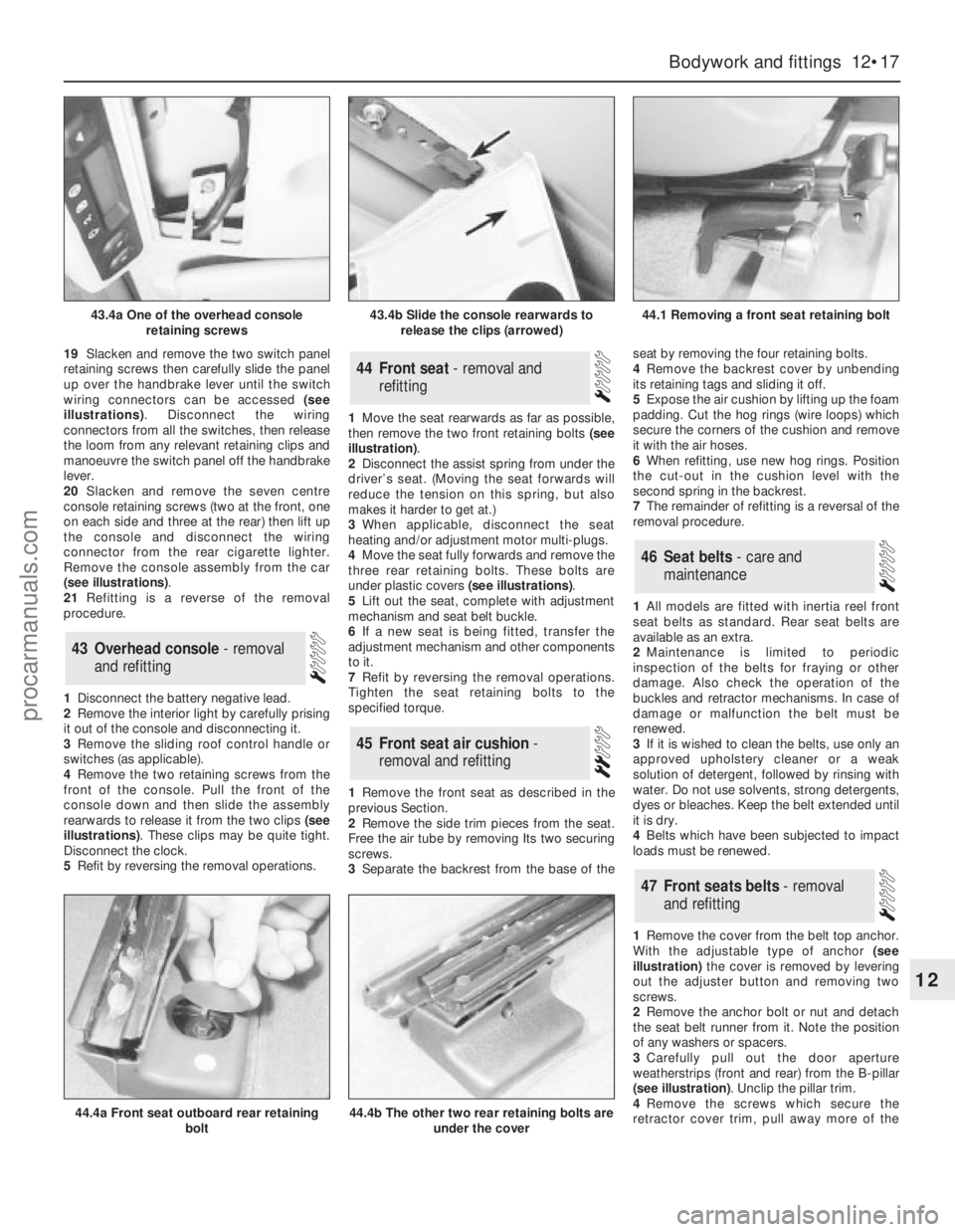
wiring connectors can be accessed (see
illustrations). Disconnect the wiring
connectors from all the switches, then release
the loom from any relevant retaining clips and
manoeuvre the switch panel off the handbrake
lever.
20Slacken and remove the seven centre
console retaining screws (two at the front, one
on each side and three at the rear) then lift up
the console and disconnect the wiring
connector from the rear cigarette lighter.
Remove the console assembly from the car
(see illustrations).
21Refitting is a reverse of the removal
procedure.
1Disconnect the battery negative lead.
2Remove the interior light by carefully prising
it out of the console and disconnecting it.
3Remove the sliding roof control handle or
switches (as applicable).
4Remove the two retaining screws from the
front of the console. Pull the front of the
console down and then slide the assembly
rearwards to release it from the two clips (see
illustrations). These clips may be quite tight.
Disconnect the clock.
5Refit by reversing the removal operations.1Move the seat rearwards as far as possible,
then remove the two front retaining bolts (see
illustration).
2Disconnect the assist spring from under the
driver’s seat. (Moving the seat forwards will
reduce the tension on this spring, but also
makes it harder to get at.)
3When applicable, disconnect the seat
heating and/or adjustment motor multi-plugs.
4Move the seat fully forwards and remove the
three rear retaining bolts. These bolts are
under plastic covers (see illustrations).
5Lift out the seat, complete with adjustment
mechanism and seat belt buckle.
6If a new seat is being fitted, transfer the
adjustment mechanism and other components
to it.
7Refit by reversing the removal operations.
Tighten the seat retaining bolts to the
specified torque.
1Remove the front seat as described in the
previous Section.
2Remove the side trim pieces from the seat.
Free the air tube by removing Its two securing
screws.
3Separate the backrest from the base of theseat by removing the four retaining bolts.
4Remove the backrest cover by unbending
its retaining tags and sliding it off.
5Expose the air cushion by lifting up the foam
padding. Cut the hog rings (wire loops) which
secure the corners of the cushion and remove
it with the air hoses.
6When refitting, use new hog rings. Position
the cut-out in the cushion level with the
second spring in the backrest.
7The remainder of refitting is a reversal of the
removal procedure.
1All models are fitted with inertia reel front
seat belts as standard. Rear seat belts are
available as an extra.
2Maintenance is limited to periodic
inspection of the belts for fraying or other
damage. Also check the operation of the
buckles and retractor mechanisms. In case of
damage or malfunction the belt must be
renewed.
3If it is wished to clean the belts, use only an
approved upholstery cleaner or a weak
solution of detergent, followed by rinsing with
water. Do not use solvents, strong detergents,
dyes or bleaches. Keep the belt extended until
it is dry.
4Belts which have been subjected to impact
loads must be renewed.
1Remove the cover from the belt top anchor.
With the adjustable type of anchor(see
illustration)the cover is removed by levering
out the adjuster button and removing two
screws.
2Remove the anchor bolt or nut and detach
the seat belt runner from it. Note the position
of any washers or spacers.
3Carefully pull out the door aperture
weatherstrips (front and rear) from the B-pillar
(see illustration). Unclip the pillar trim.
4Remove the screws which secure the
retractor cover trim, pull away more of the
47Front seats belts - removal
and refitting
46Seat belts - care and
maintenance
45Front seat air cushion -
removal and refitting
44Front seat - removal and
refitting
43Overhead console - removal
and refitting
Bodywork and fittings 12•17
12
43.4a One of the overhead console
retaining screws43.4b Slide the console rearwards to
release the clips (arrowed)44.1 Removing a front seat retaining bolt
44.4a Front seat outboard rear retaining
bolt44.4b The other two rear retaining bolts are
under the cover
procarmanuals.com
Page 190 of 255

Heated rear window switch
Models before April 1992
50Remove the instrument panel surround,
which is secured by four screws.
51Carefully prise the switch from its location,
disconnect the multi-plug and remove it.
Models from April 1992
52Using a small flat-bladed screwdriver,
carefully prise the switch out of the centre
facia vent panel and disconnect the wiring
connector.
53On refitting, reconnect the wiring
connector and push the switch in until it clicks
into position.
Foglight switch(es)
54These are removed in the same way as the
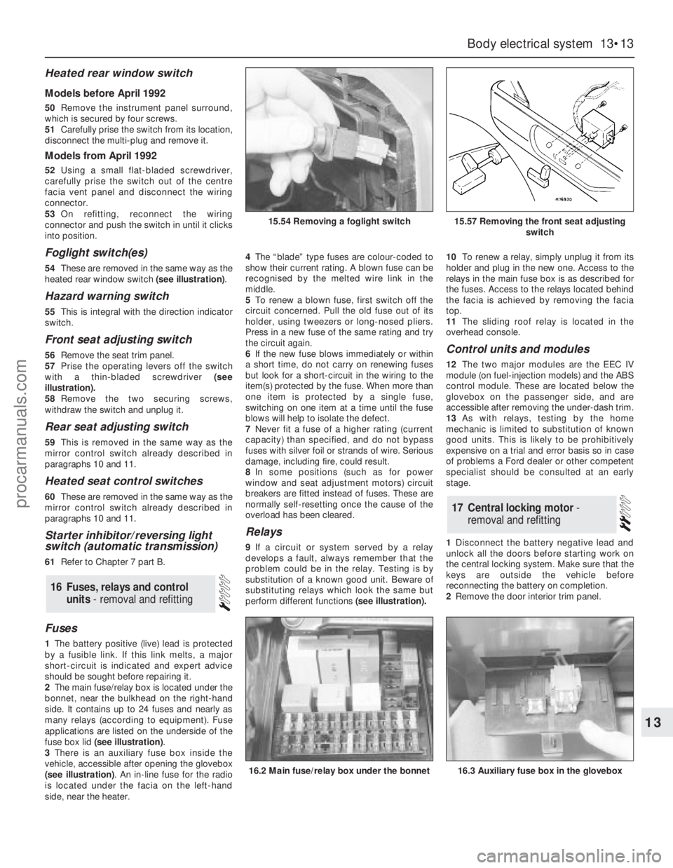
heated rear window switch (see illustration).
Hazard warning switch
55This is integral with the direction indicator
switch.
Front seat adjusting switch
56Remove the seat trim panel.
57Prise the operating levers off the switch
with a thin-bladed screwdriver (see
illustration).
58Remove the two securing screws,
withdraw the switch and unplug it.
Rear seat adjusting switch
59This is removed in the same way as the
mirror control switch already described in
paragraphs 10 and 11.
Heated seat control switches
60These are removed in the same way as the
mirror control switch already described in
paragraphs 10 and 11.
Starter inhibitor/reversing light
switch (automatic transmission)
61Refer to Chapter 7 part B.
Fuses
1The battery positive (live) lead is protected
by a fusible link. If this link melts, a major
short-circuit is indicated and expert advice
should be sought before repairing it.
2The main fuse/relay box is located under the
bonnet, near the bulkhead on the right-hand
side. It contains up to 24 fuses and nearly as
many relays (according to equipment). Fuse
applications are listed on the underside of the
fuse box lid (see illustration).
3There is an auxiliary fuse box inside the
vehicle, accessible after opening the glovebox
(see illustration). An in-line fuse for the radio
is located under the facia on the left-hand
side, near the heater.4The“blade” type fuses are colour-coded to
show their current rating. A blown fuse can be
recognised by the melted wire link in the
middle.
5To renew a blown fuse, first switch off the
circuit concerned. Pull the old fuse out of its
holder, using tweezers or long-nosed pliers.
Press in a new fuse of the same rating and try
the circuit again.
6If the new fuse blows immediately or within
a short time, do not carry on renewing fuses
but look for a short-circuit in the wiring to the
item(s) protected by the fuse. When more than
one item is protected by a single fuse,
switching on one item at a time until the fuse
blows will help to isolate the defect.
7Never fit a fuse of a higher rating (current
capacity) than specified, and do not bypass
fuses with silver foil or strands of wire. Serious
damage, including fire, could result.
8In some positions (such as for power
window and seat adjustment motors) circuit
breakers are fitted instead of fuses. These are
normally self-resetting once the cause of the
overload has been cleared.
Relays
9If a circuit or system served by a relay
develops a fault, always remember that the
problem could be in the relay. Testing is by
substitution of a known good unit. Beware of
substituting relays which look the same but
perform different functions(see illustration).10To renew a relay, simply unplug it from its
holder and plug in the new one. Access to the
relays in the main fuse box is as described for
the fuses. Access to the relays located behind
the facia is achieved by removing the facia
top.
11The sliding roof relay is located in the
overhead console.
Control units and modules
12The two major modules are the EEC IV
module (on fuel-injection models) and the ABS
control module. These are located below the
glovebox on the passenger side, and are
accessible after removing the under-dash trim.
13As with relays, testing by the home
mechanic is limited to substitution of known
good units. This is likely to be prohibitively
expensive on a trial and error basis so in case
of problems a Ford dealer or other competent
specialist should be consulted at an early
stage.
1Disconnect the battery negative lead and
unlock all the doors before starting work on
the central locking system. Make sure that the
keys are outside the vehicle before
reconnecting the battery on completion.
2Remove the door interior trim panel.
17Central locking motor -
removal and refitting
16Fuses, relays and control
units - removal and refitting
Body electrical system 13•13
13
15.54 Removing a foglight switch15.57 Removing the front seat adjusting
switch
16.2 Main fuse/relay box under the bonnet16.3 Auxiliary fuse box in the glovebox
procarmanuals.com