1985 FORD GRANADA instrument cluster
[x] Cancel search: instrument clusterPage 187 of 255
1With the instrument cluster removed, a
particular gauge or other component can be
renewed by following the appropriate parts of
this Section.
2Remove all the light bulbs and holders from
the rear of the panel by twisting them anti-
clockwise.
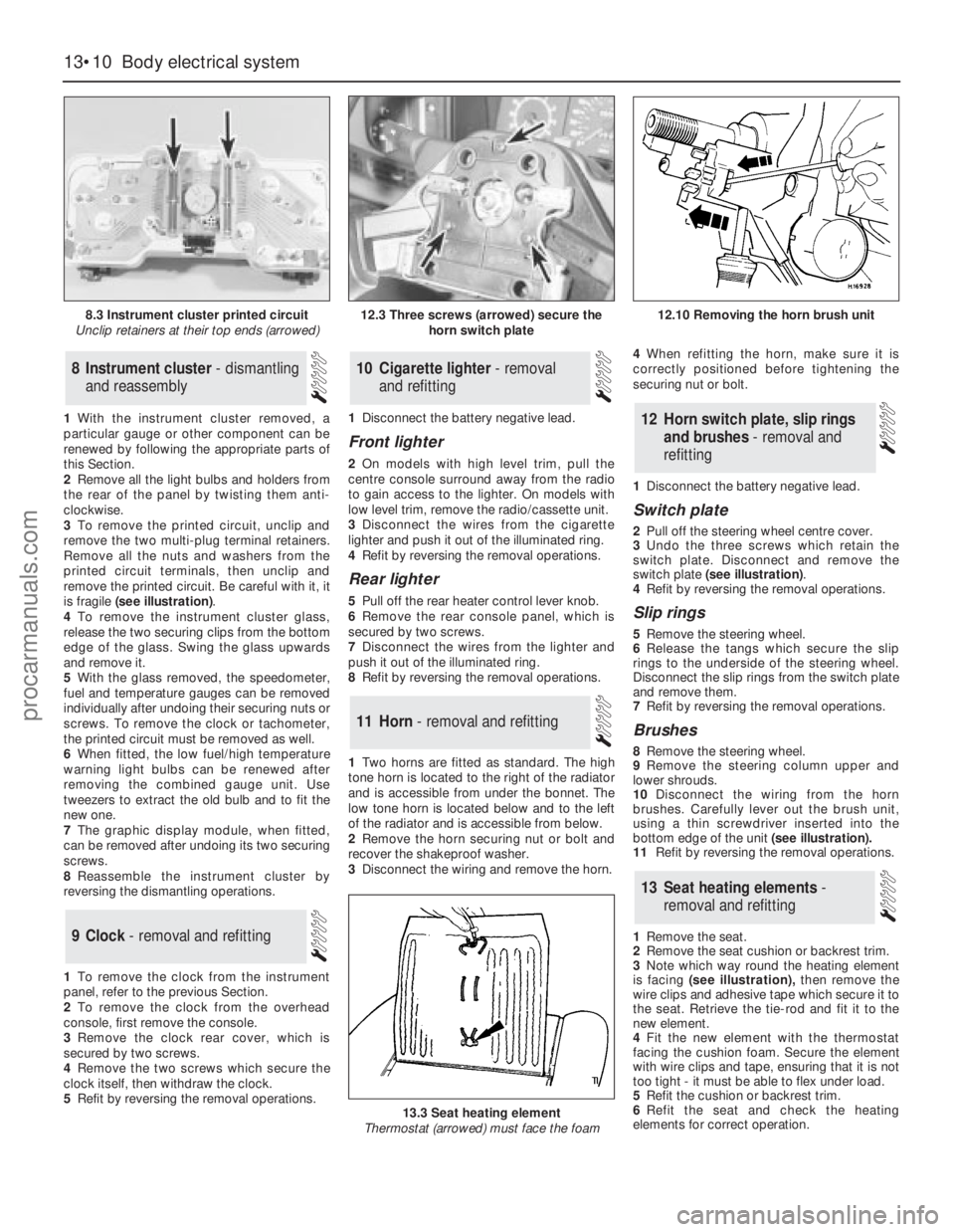
3To remove the printed circuit, unclip and
remove the two multi-plug terminal retainers.
Remove all the nuts and washers from the
printed circuit terminals, then unclip and
remove the printed circuit. Be careful with it, it
is fragile (see illustration).
4To remove the instrument cluster glass,
release the two securing clips from thebottom
edge of the glass. Swing the glass upwards
and remove it.
5With the glass removed, the speedometer,
fuel and temperature gauges can be removed
individually after undoing their securing nuts or
screws. To remove the clock or tachometer,
the printed circuit must be removed as well.
6When fitted, the low fuel/high temperature
warning light bulbs can be renewed after
removing the combined gauge unit. Use
tweezers to extract the old bulb and to fit the
new one.
7The graphic display module, when fitted,
can be removed after undoing its two securing
screws.
8Reassemble the instrument cluster by
reversing the dismantling operations.
1To remove the clock from the instrument
panel, refer to the previous Section.
2To remove the clock from the overhead
console, first remove the console.
3Remove the clock rear cover, which is
secured by two screws.
4Remove the two screws which secure the
clock itself, then withdraw the clock.
5Refit by reversing the removal operations.1Disconnect the battery negative lead.
Front lighter
2On models with high level trim, pull the
centre console surround away from the radio
to gain access to the lighter. On models with
low level trim, remove the radio/cassette unit.
3Disconnect the wires from the cigarette
lighter and push it out of the illuminated ring.
4Refit by reversing the removal operations.
Rear lighter
5Pull off the rear heater control lever knob.
6Remove the rear console panel, which is
secured by two screws.
7Disconnect the wires from the lighter and
push it out of the illuminated ring.
8Refit by reversing the removal operations.
1Two horns are fitted as standard. The high
tone horn is located to the right of the radiator
and is accessible from under the bonnet. The
low tone horn is located below and to the left
of the radiator and is accessible from below.
2Remove the horn securing nut or bolt and
recover the shakeproof washer.
3Disconnect the wiring and remove the horn.4When refitting the horn, make sure it is
correctly positioned before tightening the
securing nut or bolt.
1Disconnect the battery negative lead.
Switch plate
2Pull off the steering wheel centre cover.
3Undo the three screws which retain the
switch plate. Disconnect and remove the
switch plate (see illustration).
4Refit by reversing the removal operations.
Slip rings
5Remove the steering wheel.
6Release the tangs which secure the slip
rings to the underside of the steering wheel.
Disconnect the slip rings from the switch plate
and remove them.
7Refit by reversing the removal operations.
Brushes
8Remove the steering wheel.
9Remove the steering column upper and
lower shrouds.
10Disconnect the wiring from the horn
brushes. Carefully lever out the brush unit,
using a thin screwdriver inserted into the
bottom edge of the unit(see illustration).
11Refit by reversing the removal operations.
1Remove the seat.
2Remove the seat cushion or backrest trim.
3Note which way round the heating element
is facing (see illustration),then remove the
wire clips and adhesive tape which secure it to
the seat. Retrieve the tie-rod and fit it to the
new element.
4Fit the new element with the thermostat
facing the cushion foam. Secure the element
with wire clips and tape, ensuring that it is not
too tight - it must be able to flex under load.
5Refit the cushion or backrest trim.
6Refit the seat and check the heating
elements for correct operation.
13Seat heating elements -
removal and refitting
12Horn switch plate, slip rings
and brushes - removal and
refitting
11Horn - removal and refitting
10Cigarette lighter - removal
and refitting
9Clock - removal and refitting
8Instrument cluster - dismantling
and reassembly
13•10Body electrical system
8.3 Instrument cluster printed circuit
Unclip retainers at their top ends (arrowed)
13.3 Seat heating element
Thermostat (arrowed) must face the foam
12.3 Three screws (arrowed) secure the
horn switch plate12.10 Removing the horn brush unit
procarmanuals.com
Page 188 of 255
1Disconnect the battery negative lead.
2Remove the steering column upper and
lower shrouds.
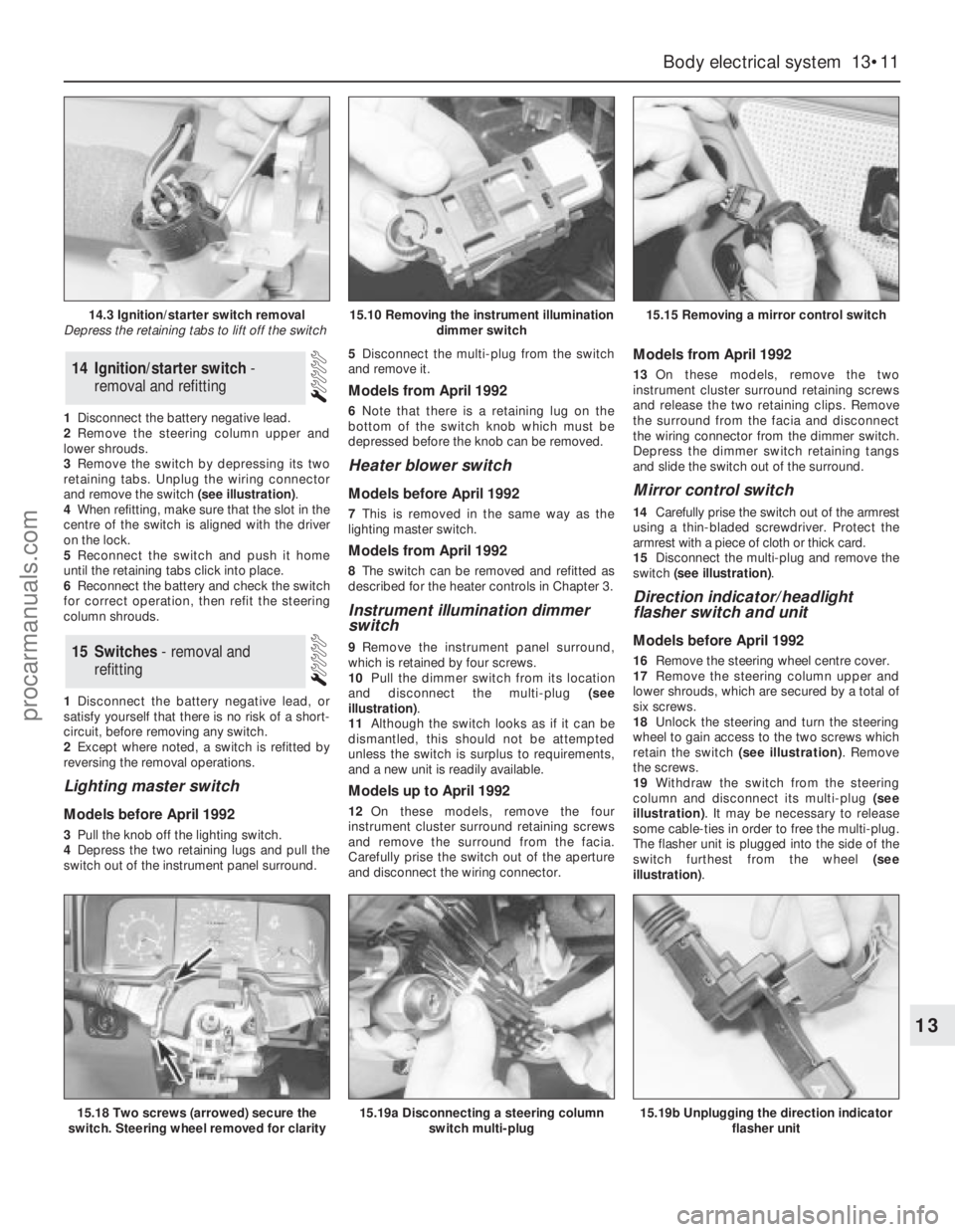
3Remove the switch by depressing its two
retaining tabs. Unplug the wiring connector
and remove the switch (see illustration).
4When refitting, make sure that the slot in the
centre of the switch is aligned with the driver
on the lock.
5Reconnect the switch and push it home
until the retaining tabs click into place.
6Reconnect the battery and check the switch
for correct operation, then refit the steering
column shrouds.
1Disconnect the battery negative lead, or
satisfy yourself that there is no risk of a short-
circuit, before removing any switch.
2Except where noted, a switch is refitted by
reversing the removal operations.
Lighting master switch
Models before April 1992
3Pull the knob off the lighting switch.
4Depress the two retaining lugs and pull the
switch out of the instrument panel surround. 5Disconnect the multi-plug from the switch
and remove it.
Models from April 1992
6Note that there is a retaining lug on the
bottom of the switch knob which must be
depressed before the knob can be removed.
Heater blower switch
Models before April 1992
7This is removed in the same way as the
lighting master switch.
Models from April 1992
8The switch can be removed and refitted as
described for the heater controls in Chapter 3.
Instrument illumination dimmer
switch
9Remove the instrument panel surround,
which is retained by four screws.
10Pull the dimmer switch from its location
and disconnect the multi-plug (see
illustration).
11Although the switch looks as if it can be
dismantled, this should not be attempted
unless the switch is surplus to requirements,
and a new unit is readily available.
Models up to April 1992
12On these models, remove the four
instrument cluster surround retaining screws
and remove the surround from the facia.
Carefully prise the switch out of the aperture
and disconnect the wiring connector.
Models from April 1992
13On these models, remove the two
instrument cluster surround retaining screws
and release the two retaining clips. Remove
the surround from the facia and disconnect
the wiring connector from the dimmer switch.
Depress the dimmer switch retaining tangs
and slide the switch out of the surround.
Mirror control switch
14Carefully prise the switch out of the armrest
using a thin-bladed screwdriver. Protect the
armrest with a piece of cloth or thick card.
15Disconnect the multi-plug and remove the
switch (see illustration).
Direction indicator/headlight
flasher switch and unit
Models before April 1992
16Remove the steering wheel centre cover.
17Remove the steering column upper and
lower shrouds, which are secured by a total of
six screws.
18Unlock the steering and turn the steering
wheel to gain access to the two screws which
retain the switch (see illustration). Remove
the screws.
19Withdraw the switch from the steering
column and disconnect its multi-plug (see
illustration). It may be necessary to release
some cable-ties in order to free the multi-plug.
The flasher unit is plugged into the side of the
switch furthest from the wheel (see
illustration).15Switches - removal and
refitting
14Ignition/starter switch -
removal and refitting
Body electrical system 13•11
13
14.3 Ignition/starter switch removal
Depress the retaining tabs to lift off the switch15.10 Removing the instrument illumination
dimmer switch15.15 Removing a mirror control switch
15.18 Two screws (arrowed) secure the
switch. Steering wheel removed for clarity15.19a Disconnecting a steering column
switch multi-plug15.19b Unplugging the direction indicator
flasher unit
procarmanuals.com
Page 195 of 255
Computer module and bulb
Models before April 1992
2Remove the instrument panel surround,
which is secured by four screws.
3Carefully pull the module from its location.
Release the multi-plug by pressing
downwards and disconnect it.
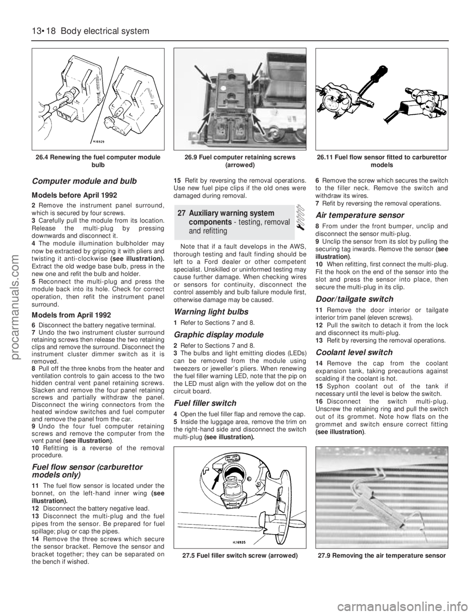
4The module illumination bulbholder may
now be extracted by gripping it with pliers and
twisting it anti-clockwise (see illustration).
Extract the old wedge base bulb, press in the
new one and refit the bulb and holder.
5Reconnect the multi-plug and press the
module back into its hole. Check for correct
operation, then refit the instrument panel
surround.
Models from April 1992
6Disconnect the battery negative terminal.
7Undo the two instrument cluster surround
retaining screws then release the two retaining
clips and remove the surround. Disconnect the
instrument cluster dimmer switch as it is
removed.
8Pull off the three knobs from the heater and
ventilation controls to gain access to the two
hidden central vent panel retaining screws.
Slacken and remove the four panel retaining
screws and partially withdraw the panel.
Disconnect the wiring connectors from the
heated window switches and fuel computer
and remove the panel from the car.
9Undo the four fuel computer retaining
screws and remove the computer from the
vent panel (see illustration).
10Refitting is a reverse of the removal
procedure.
Fuel flow sensor (carburettor
models only)
11The fuel flow sensor is located under the
bonnet, on the left-hand inner wing (see
illustration).
12Disconnect the battery negative lead.
13Disconnect the multi-plug and the fuel
pipes from the sensor. Be prepared for fuel
spillage; plug or cap the pipes.
14Remove the three screws which secure
the sensor bracket. Remove the sensor and
bracket together; they can be separated on
the bench if wished.15Refit by reversing the removal operations.
Use new fuel pipe clips if the old ones were
damaged during removal.
Note that if a fault develops in the AWS,
thorough testing and fault finding should be
left to a Ford dealer or other competent
specialist. Unskilled or uninformed testing may
cause further damage. When checking wires
or sensors for continuity, disconnect the
control assembly and bulb failure module first,
otherwise damage may be caused.
Warning light bulbs
1Refer to Sections 7 and 8.
Graphic display module
2Refer to Sections 7 and 8.
3The bulbs and light emitting diodes (LEDs)
can be removed from the module using
tweezers or jeweller’s pliers. When renewing
the fuel filler warning LED, note that the pip on
the LED must align with the yellow dot on the
circuit board.
Fuel filler switch
4Open the fuel filler flap and remove the cap.
5Inside the luggage area, remove the trim on
the right-hand side and disconnect the switch
multi-plug(see illustration).6Remove the screw which secures the switch
to the filler neck. Remove the switch and
withdraw its wires.
7Refit by reversing the removal operations.
Air temperature sensor
8From under the front bumper, unclip and
disconnect the sensor multi-plug.
9Unclip the sensor from its slot by pulling the
securing tag inwards. Remove the sensor (see
illustration).
10When refitting, first connect the multi-plug.
Fit the hook on the end of the sensor into the
slot and press the sensor into place, then
secure the multi-plug in its clip.
Door/tailgate switch
11Remove the door interior ortailgate
interior trim panel (eleven screws).
12Pull the switch to detach it from the lock
and disconnect its multi-plug.
13Refit by reversing the removal operations.
Coolant level switch
14Remove the cap from the coolant
expansion tank, taking precautions against
scalding if the coolant is hot.
15Syphon coolant out of the tank if
necessary until the level is below the switch.
16Disconnect the switch multi-plug.
Unscrew the retaining ring and pull the switch
out of its grommet. Note how flats on the
grommet and switch ensure correct fitting
(see illustration).
27Auxiliary warning system
components - testing, removal
and refitting
13•18Body electrical system
26.4 Renewing the fuel computer module
bulb
27.5 Fuel filler switch screw (arrowed)27.9 Removing the air temperature sensor
26.9 Fuel computer retaining screws
(arrowed)26.11 Fuel flow sensor fitted to carburettor
models
procarmanuals.com
Page 199 of 255
High frequency units
14Remove the instrument panel surround
and the facia top.
15Remove the two screws which secure the
speaker bracket. Disconnect the wiring and
withdraw the speaker and bracket together.
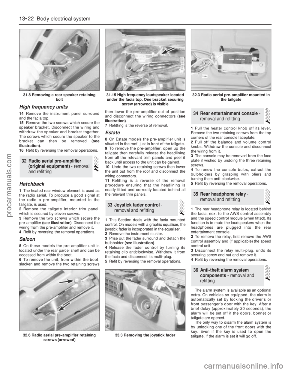
The screws which secure the speaker to the
bracket can then be removed (see
illustration).
16Refit by reversing the removal operations.
Hatchback
1The heated rear window element is used as
the radio aerial. To produce a good signal at
the radio a pre-amplifier, mounted in the
tailgate, is used.
2Remove the tailgate interior trim panel,
which is secured by eleven screws.
3Remove the two screws which secure the
pre-amplifier (see illustration). Disconnect the
wiring from the pre-amplifier and remove it.
4Refit by reversing the removal operations.
Saloon
5On these models the pre-amplifier unit is
located under the rear parcel shelf and can be
accessed from within the boot.
6To remove the unit, from within the boot,
slacken and remove the two retaining screwsthen lower the pre-amplifier out of position
and disconnect the wiring connectors (see
illustration).
7Refitting is the reverse of removal.
Estate
8On Estate models the pre-amplifier unit is
situated in the roof, just in front of the tailgate.
9To remove the pre-amplifier, open up the
tailgate then carefully release the headlining
from all the relevant trim panels and peel it
back until access to the unit can be gained.
10Undo the two retaining screws then lower
the unit out from the roof and disconnect the
wiring connectors.
11Refitting is a reverse of the removal
procedure ensuring that the headlining is
neatly fitted and correctly located behind all
the relevant trim panels.
1This Section deals with the facia-mounted
control. On models with a graphic equaliser, the
joystick fader is incorporated in the equaliser.
2Remove the instrument cluster.
3Prise out the fader surround and detach the
bulbholder (see illustration).
4Release the fader control by turning its
retaining clip anticlockwise. Withdraw it from
the facia and disconnect its multi-plug.
5Refit by reversing the removal operations.1Pull the heater control knob off its lever.
Remove the two retaining screws from the top
corners of the rear console faceplate.
2Pull off the balance and volume control
knobs. Withdraw the console and disconnect
the wiring from it.
3The console may be removed from the face
plate if wished by undoing the three retaining
screws.
4To renew the console bulbs, extract the
bulbholders by grasping with pliers and
turning them anti-clockwise.
5Refit by reversing the removal operations.
1The rear headphone relay is located behind
the facia, next to the AWS control assembly
and the speed control module (when fitted). Its
function is to mute the loudspeakers when the
headphones are plugged into the rear
entertainment console.
2To remove the relay, first remove the AWS
control assembly and (if applicable) the speed
control unit.
3Disconnect the relay multi-plug, undo its
securing screw and nut and remove it.
4Refit by reversing the removal operations.
The alarm system is available as an optional
extra. On vehicles so equipped, the alarm is
automatically set by locking the driver’s or
front passenger’s door with the key. After a
brief delay (approximately 20 seconds), the
alarm will be set off if the doors, bonnet or
tailgate are opened.
The only way to disarm the alarm system is
by unlocking one of the front doors with the
key. Even if the key is used to open the
tailgate, if the alarm is set it will go off.
36Anti-theft alarm system
components - removal and
refitting
35Rear headphone relay -
removal and refitting
34Rear entertainment console -
removal and refitting
33Joystick fader control -
removal and refitting
32Radio aerial pre-amplifier
(original equipment) - removal
and refitting
13•22Body electrical system
31.8 Removing a rear speaker retaining
bolt
32.6 Radio aerial pre-amplifier retaining
screws (arrowed)33.3 Removing the joystick fader
31.15 High frequency loudspeaker located
under the facia top. One bracket securing
screw (arrowed) is visible32.3 Radio aerial pre-amplifier mounted in
the tailgate
procarmanuals.com
Page 253 of 255
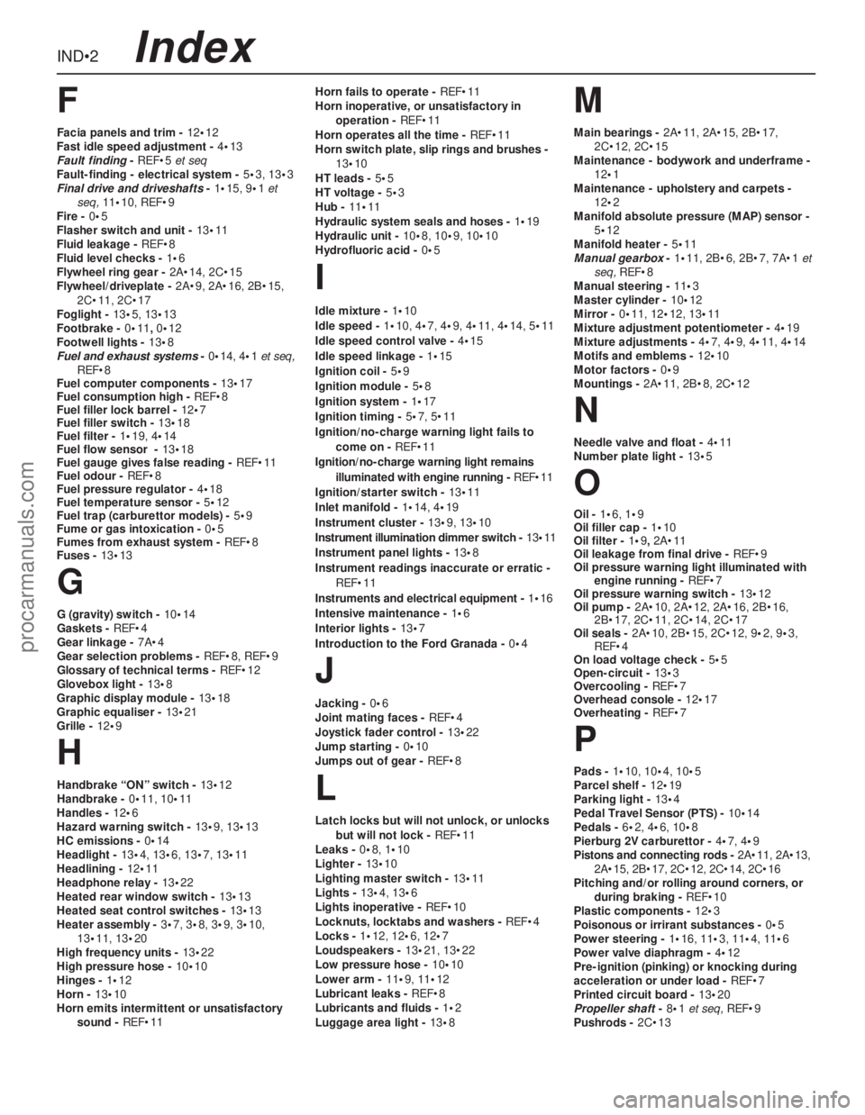
IND•2
F
Facia panels and trim - 12•12
Fast idle speed adjustment - 4•13
Fault finding- REF•5et seq
Fault-finding - electrical system - 5•3, 13•3
Final drive and driveshafts- 1•15, 9•1et
seq, 11•10, REF•9
Fire - 0•5
Flasher switch and unit - 13•11
Fluid leakage - REF•8
Fluid level checks - 1•6
Flywheel ring gear - 2A•14, 2C•15
Flywheel/driveplate - 2A•9, 2A•16, 2B•15,
2C•11, 2C•17
Foglight - 13•5,13•13
Footbrake - 0•11, 0•12
Footwell lights - 13•8
Fuel and exhaust systems- 0•14, 4•1et seq,
REF•8
Fuel computer components - 13•17
Fuel consumption high - REF•8
Fuel filler lock barrel - 12•7
Fuel filler switch - 13•18
Fuel filter - 1•19, 4•14
Fuel flow sensor - 13•18
Fuel gauge gives false reading - REF•11
Fuel odour - REF•8
Fuel pressure regulator - 4•18
Fuel temperature sensor - 5•12
Fuel trap (carburettor models) - 5•9
Fume or gas intoxication - 0•5
Fumes from exhaust system - REF•8
Fuses - 13•13
G
G (gravity) switch - 10•14
Gaskets - REF•4
Gear linkage - 7A•4
Gear selection problems - REF•8, REF•9
Glossary of technical terms - REF•12
Glovebox light - 13•8
Graphic display module - 13•18
Graphic equaliser - 13•21
Grille - 12•9
H
Handbrake “ON” switch - 13•12
Handbrake - 0•11, 10•11
Handles - 12•6
Hazard warning switch - 13•9, 13•13
HC emissions - 0•14
Headlight - 13•4, 13•6, 13•7, 13•11
Headlining - 12•11
Headphone relay - 13•22
Heated rear window switch - 13•13
Heated seat control switches - 13•13
Heater assembly - 3•7, 3•8, 3•9, 3•10,
13•11, 13•20
High frequency units - 13•22
High pressure hose - 10•10
Hinges - 1•12
Horn - 13•10
Horn emits intermittent or unsatisfactory
sound - REF•11Horn fails to operate - REF•11
Horn inoperative, or unsatisfactory in
operation - REF•11
Horn operates all the time - REF•11
Horn switch plate, slip rings and brushes -
13•10
HT leads - 5•5
HT voltage - 5•3
Hub - 11•11
Hydraulic system seals and hoses - 1•19
Hydraulic unit - 10•8, 10•9, 10•10
Hydrofluoric acid - 0•5
I
Idle mixture - 1•10
Idle speed - 1•10, 4•7, 4•9, 4•11, 4•14, 5•11
Idle speed control valve - 4•15
Idle speed linkage - 1•15
Ignition coil - 5•9
Ignition module - 5•8
Ignition system - 1•17
Ignition timing - 5•7, 5•11
Ignition/no-charge warning light fails to
come on - REF•11
Ignition/no-charge warning light remains
illuminated with engine running - REF•11
Ignition/starter switch - 13•11
Inlet manifold - 1•14, 4•19
Instrument cluster - 13•9, 13•10
Instrument illumination dimmer switch - 13•11
Instrument panel lights - 13•8
Instrument readings inaccurate or erratic -
REF•11
Instruments and electrical equipment - 1•16
Intensive maintenance - 1•6
Interior lights - 13•7
Introduction to the Ford Granada - 0•4
J
Jacking - 0•6
Joint mating faces - REF•4
Joystick fader control - 13•22
Jump starting - 0•10
Jumps out of gear - REF•8
L
Latch locks but will not unlock, or unlocks
but will not lock - REF•11
Leaks - 0•8, 1•10
Lighter - 13•10
Lighting master switch - 13•11
Lights - 13•4, 13•6
Lights inoperative - REF•10
Locknuts, locktabs and washers - REF•4
Locks - 1•12, 12•6, 12•7
Loudspeakers - 13•21, 13•22
Low pressure hose - 10•10
Lower arm - 11•9, 11•12
Lubricant leaks - REF•8
Lubricants and fluids - 1•2
Luggage area light - 13•8
M
Main bearings - 2A•11, 2A•15, 2B•17,
2C•12, 2C•15
Maintenance - bodywork and underframe -
12•1
Maintenance - upholstery and carpets -
12•2
Manifold absolute pressure (MAP) sensor -
5•12
Manifold heater - 5•11
Manual gearbox- 1•11, 2B•6, 2B•7, 7A•1et
seq, REF•8
Manual steering - 11•3
Master cylinder - 10•12
Mirror - 0•11, 12•12, 13•11
Mixture adjustment potentiometer - 4•19
Mixture adjustments - 4•7, 4•9, 4•11, 4•14
Motifs and emblems - 12•10
Motor factors - 0•9
Mountings - 2A•11, 2B•8, 2C•12
N
Needle valve and float - 4•11
Number plate light - 13•5
O
Oil - 1•6, 1•9
Oil filler cap - 1•10
Oil filter - 1•9, 2A•11
Oil leakage from final drive - REF•9
Oil pressure warning light illuminated with
engine running - REF•7
Oil pressure warning switch - 13•12
Oil pump - 2A•10, 2A•12, 2A•16, 2B•16,
2B•17, 2C•11, 2C•14, 2C•17
Oil seals - 2A•10, 2B•15, 2C•12, 9•2, 9•3,
REF•4
On load voltage check - 5•5
Open-circuit - 13•3
Overcooling - REF•7
Overhead console - 12•17
Overheating - REF•7
P
Pads - 1•10, 10•4, 10•5
Parcel shelf - 12•19
Parking light - 13•4
Pedal Travel Sensor (PTS) - 10•14
Pedals - 6•2, 4•6, 10•8
Pierburg 2V carburettor - 4•7, 4•9
Pistons and connecting rods - 2A•11, 2A•13,
2A•15, 2B•17, 2C•12, 2C•14, 2C•16
Pitching and/or rolling around corners, or
during braking - REF•10
Plastic components - 12•3
Poisonous or irrirant substances - 0•5
Power steering - 1•16, 11•3, 11•4, 11•6
Power valve diaphragm - 4•12
Pre-ignition (pinking) or knocking during
acceleration or under load - REF•7
Printed circuit board - 13•20
Propeller shaft- 8•1et seq, REF•9
Pushrods - 2C•13
Index
procarmanuals.com