1985 FORD GRANADA spark plugs replace
[x] Cancel search: spark plugs replacePage 14 of 255

DOHC engines
12On this engine, the coolant/alternator
drivebelt also drives the power steering pump
and (where applicable) the air conditioning
compressor. The drivebelt tension is set by an
automatic tensioner assembly.
13The condition of the drivebelt should be
checked as described above.
14An idea of the amount of wear which has
taken place on the belt can be gained from the
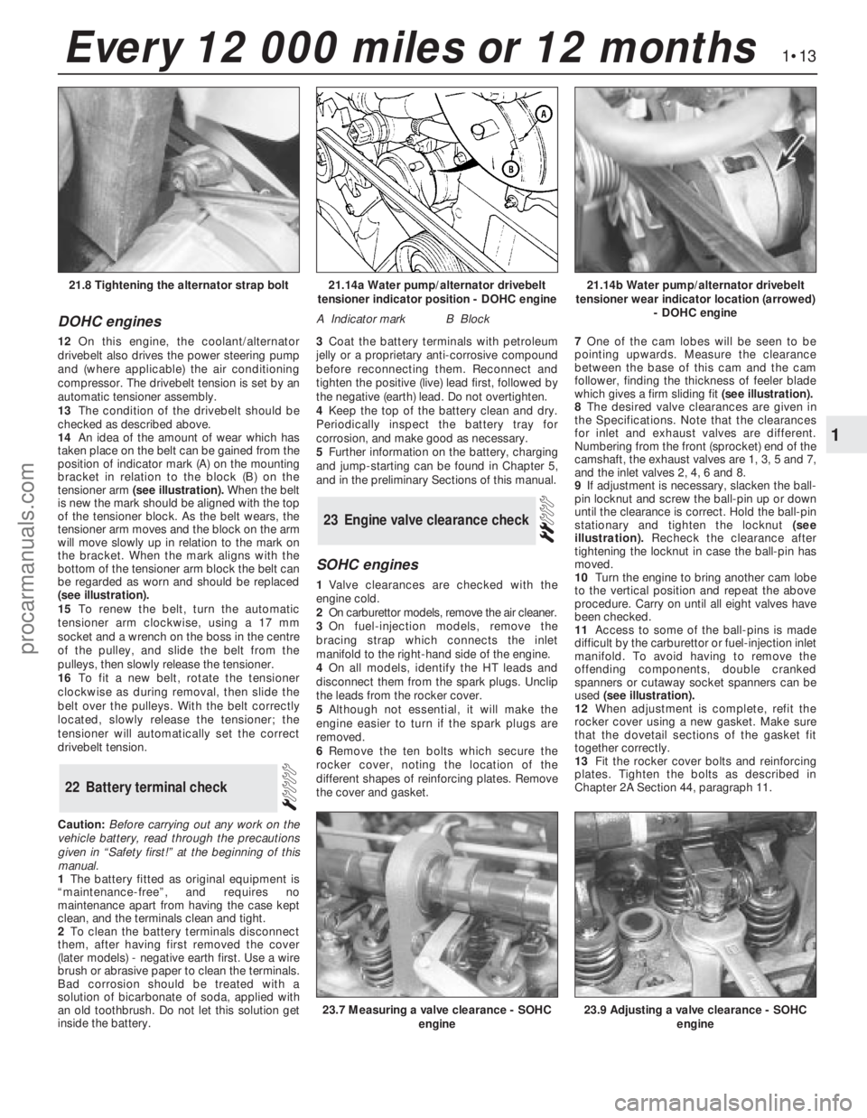
position of indicator mark (A) on the mounting
bracket in relation to the block (B) on the
tensioner arm (see illustration).When the belt
is new the mark should be aligned with the top
of the tensioner block. As the belt wears, the
tensioner arm moves and the block on the arm
will move slowly up in relation to the mark on
the bracket. When the mark aligns with the
bottom of the tensioner arm block the belt can
be regarded as worn and should be replaced
(see illustration).
15To renew the belt, turn the automatic
tensioner arm clockwise, using a 17 mm
socket and a wrench on the boss in the centre
of the pulley, and slide the belt from the
pulleys, then slowly release the tensioner.
16To fit a new belt, rotate the tensioner
clockwise as during removal, then slide the
belt over the pulleys. With the belt correctly
located, slowly release the tensioner; the
tensioner will automatically set the correct
drivebelt tension.
Caution:Before carrying out any work on the
vehicle battery, read through the precautions
given in “Safety first!” at the beginning of this
manual.
1The battery fitted as original equipment is
“maintenance-free”, and requires no
maintenance apart from having the case kept
clean, and the terminals clean and tight.
2To clean the battery terminals disconnect
them, after having first removed the cover
(later models) -negative earth first. Use a wire
brush or abrasive paper to clean the terminals.
Bad corrosion should be treated with a
solution of bicarbonate of soda, applied with
an old toothbrush. Do not let this solution get
inside the battery.3Coat the battery terminals with petroleum
jelly or a proprietary anti-corrosive compound
before reconnecting them. Reconnect and
tighten the positive (live) lead first, followed by
the negative (earth) lead. Do not overtighten.
4Keep the top of the battery clean and dry.
Periodically inspect the battery tray for
corrosion, and make good as necessary.
5Further information on the battery, charging
and jump-starting can be found in Chapter 5,
and in the preliminary Sections of this manual.
SOHC engines
1Valve clearances are checked with the
engine cold.
2On carburettor models, remove the air cleaner.
3On fuel-injection models, remove the
bracing strap which connects the inlet
manifold to the right-hand side of the engine.
4On all models, identify the HT leads and
disconnect them from the spark plugs. Unclip
the leads from the rocker cover.
5Although not essential, it will make the
engine easier to turn if the spark plugs are
removed.
6Remove the ten bolts which secure the
rocker cover, noting the location of the
different shapes of reinforcing plates. Remove
the cover and gasket.7One of the cam lobes will be seen to be
pointing upwards. Measure the clearance
between the base of this cam and the cam
follower, finding the thickness of feeler blade
which gives a firm sliding fit(see illustration).
8The desired valve clearances are given in
the Specifications. Note that the clearances
for inlet and exhaust valves are different.
Numbering from the front (sprocket) end of the
camshaft, the exhaust valves are 1, 3, 5 and 7,
and the inlet valves 2, 4, 6 and 8.
9If adjustment is necessary, slacken the ball-
pin locknut and screw the ball-pin up or down
until the clearance is correct. Hold the ball-pin
stationary and tighten the locknut(see
illustration).Recheck the clearance after
tightening the locknut in case the ball-pin has
moved.
10Turn the engine to bring another cam lobe
to the vertical position and repeat the above
procedure. Carry on until all eight valves have
been checked.
11Access to some of the ball-pins is made
difficult by the carburettor or fuel-injection inlet
manifold. To avoid having to remove the
offending components, double cranked
spanners or cutaway socket spanners can be
used (see illustration).
12When adjustment is complete, refit the
rocker cover using a new gasket. Make sure
that the dovetail sections of the gasket fit
together correctly.
13Fit the rocker cover bolts and reinforcing
plates. Tighten the bolts as described in
Chapter 2A Section 44, paragraph 11.
23Engine valve clearance check
22Battery terminal check
1•13
1
Every 12 000 miles or 12 months
21.14a Water pump/alternator drivebelt
tensioner indicator position - DOHC engine
A Indicator markB Block
21.14b Water pump/alternator drivebelt
tensioner wear indicator location (arrowed)
- DOHC engine21.8 Tightening the alternator strap bolt
23.7 Measuring a valve clearance - SOHC
engine23.9 Adjusting a valve clearance - SOHC
engine
procarmanuals.com
Page 29 of 255

14Take the weight of the engine and remove
the two engine bearer-to-mounting nuts.
15Lift the engine/transmission, at the same
time lowering the trolley jack. Draw the unit
forwards and lift it out of the engine bay.
16Temporarily refit the anti-roll bar if the
vehicle is to be moved.
1With the engine and gearbox on the bench,
remove the starter motor.
2Remove the bolt from the engine adapter plate.
3Remove the bracing strap and the
remaining engine-to-bellhousing bolts.
4With the aid of an assistant draw the
gearbox off the engine. Do not allow the weight
of the gearbox to hang on the input shaft.
1It is best to mount the engine on a
dismantling stand, but if this is not available,
stand the engine on a strong bench at a
comfortable working height. Failing this, it will
have to be stripped down on the floor.
2Cleanliness is most important, and if the
engine is dirty, it should be cleaned with
paraffin while keeping it in an upright position.
3Avoid working with the engine on a concrete
floor, as grit can be a real source of trouble.
4As parts are removed, clean them in paraffin.
However, do not immerse parts with internal
oilways in paraffin as it is difficult to remove,
usually requiring a high pressure hose.
5It is advisable to have suitable containers to
hold small items according to their use, as this
will help when reassembling the engine and
also prevent possible losses.
6Always obtain complete sets of gaskets
when the engine is being dismantled, but
retain the old gaskets with a view of using
them as a pattern to make a replacement if a
new one is not available.7When possible, refit nuts, bolts and washers
in their location after being removed, as this
helps protect the threads and will also be
helpful when reassembling the engine.
8Retain unserviceable components in order
to compare them with the new parts supplied.
9A Torx key, size T55, will be needed for
dealing with the cylinder head bolts. A 12-
spline key (to fit bolt size M8) will be needed
for the oil pump bolts. Other Torx and 12-
spline bolts may be encountered; sets of the
keys required to deal with them are available
from most motor accessory shops and tool
factors.
10Another tool which is useful, though by no
means essential, is a valve spring compressor
of the type which hooks under the camshaft
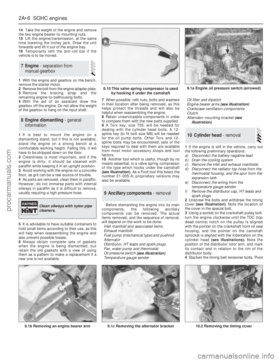
(see illustration). As a Ford tool this bears the
number 21-005-A; proprietary versions may
also be available.
Before dismantling the engine into its main
components, the following ancillary
components can be removed. The actual
items removed, and the sequence of removal,
will depend on the work to be done:
Inlet manifold and associated items
Exhaust manifold
Fuel pump (mechanical type) and pushrod
Alternator
Distributor, HT leads and spark plugs
Fan, water pump and thermostat
Oil pressure switch
(see illustration)
Temperature gauge senderOil filter and dipstick
Engine bearer arms (see illustration)
Crankcase ventilation components
Clutch
Alternator mounting bracket (see
illustration)
1If the engine is still in the vehicle, carry out
the following preliminary operations:
a)Disconnect the battery negative lead
b)Drain the cooling system
c)Remove the inlet and exhaust manifolds
d)Disconnect the radiator top hose from the
thermostat housing, and the spur from the
expansion tank
e)Disconnect the wiring from the
temperature gauge sender
f)Remove the distributor cap, HT leads and
spark plugs
2Unscrew the bolts and withdraw the timing
cover (see illustration). Note the location of
the cover in the special bolt.
3Using a socket on the crankshaft pulley bolt.
turn the engine clockwise until the TDC (top
dead centre) notch on the pulley is aligned
with the pointer on the crankshaft front oil seal
housing, and the pointer on the camshaft
sprocket is aligned with the indentation on the
cylinder head (see illustrations).Note the
position of the distributor rotor arm, and mark
its contact end in relation to the rim of the
distributor body.
4Slacken the timing belt tensioner bolts. Pivot
10Cylinder head - removal
9Ancillary components - removal
8Engine dismantling - general
information
7Engine - separation from
manual gearbox
2A•6SOHCengines
9.1a Engine oil pressure switch (arrowed)
9.1b Removing an engine bearer arm9.1c Removing the alternator bracket
8.10 This valve spring compressor is used
by hooking it under the camshaft
Clean oilways with nylon pipe
cleaners.
10.2 Removing the timing cover
procarmanuals.com
Page 110 of 255

12Extract the retaining clips and pull the
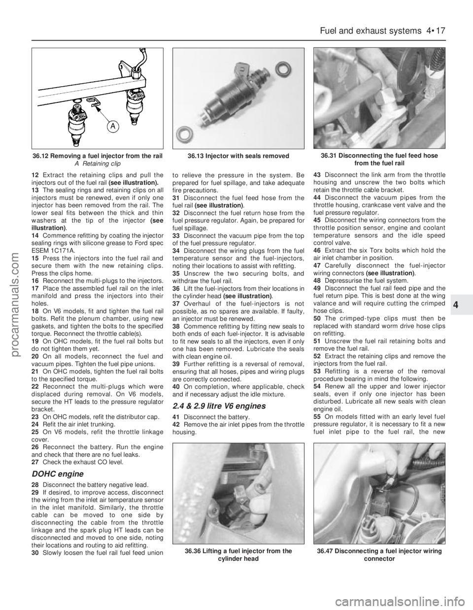
injectors out of the fuel rail(see illustration).
13The sealing rings and retaining clips on all
injectors must be renewed, even if only one
injector has been removed from the rail. The
lower seal fits between the thick and thin
washers at the tip of the injector (see
illustration).
14Commence refitting by coating the injector
sealing rings with silicone grease to Ford spec
ESEM 1C171A.
15Press the injectors into the fuel rail and
secure them with the new retaining clips.
Press the clips home.
16Reconnect the multi-plugs to the injectors.
17Place the assembled fuel rail on the inlet
manifold and press the injectors into their
holes.
18On V6 models, fit and tighten the fuel rail
bolts. Refit the plenum chamber, using new
gaskets, and tighten the bolts to the specified
torque. Reconnect the throttle cable(s).
19On OHCmodels, fit the fuel rail bolts but
do not tighten them yet.
20On all models, reconnect the fuel and
vacuum pipes. Tighten the fuel pipe unions.
21On OHCmodels, tighten the fuel rail bolts
to the specified torque.
22Reconnect the multi-plugs which were
displaced during removal. On V6 models,
secure the HT leads to the pressure regulator
bracket.
23On OHCmodels, refit the distributor cap.
24Refit the air inlet trunking.
25On V6 models, refit the throttle linkage
cover.
26Reconnect the battery. Run the engine
and check that there are no fuel leaks.
27Check the exhaust CO level.
DOHC engine
28Disconnect the battery negative lead.
29If desired, to improve access, disconnect
the wiring from the inlet air temperature sensor
in the inlet manifold. Similarly, the throttle
cable can be moved to one side by
disconnecting the cable from the throttle
linkage and the spark plug HT leads can be
disconnected and moved to one side, noting
their locations and routing to aid refitting.
30Slowly loosen the fuel rail fuel feed unionto relieve the pressure in the system. Be
prepared for fuel spillage, and take adequate
fire precautions.
31Disconnect the fuel feed hose from the
fuel rail (see illustration).
32Disconnect the fuel return hose from the
fuel pressure regulator. Again, be prepared for
fuel spillage.
33Disconnect the vacuum pipe from the top
of the fuel pressure regulator.
34Disconnect the wiring plugs from the fuel
temperature sensor and the fuel-injectors,
noting their locations to assist with refitting.
35Unscrew the two securing bolts, and
withdraw the fuel rail.
36Lift the fuel-injectors from their locations in
the cylinder head (see illustration).
37Overhaul of the fuel-injectors is not
possible, as no spares are available. If faulty,
an injector must be renewed.
38Commence refitting by fitting new seals to
both ends of each fuel-injector. It is advisable
to fit new seals to all the injectors, even if only
one has been removed. Lubricate the seals
with clean engine oil.
39Further refitting is a reversal of removal,
ensuring that all hoses, pipes and wiring plugs
are correctly connected.
40On completion, where applicable, check
and if necessary adjust the idle mixture.
2.4 & 2.9 litre V6 engines
41Disconnect the battery.
42Remove the air inlet pipes from the throttle
housing.43Disconnect the link arm from the throttle
housing and unscrew the two bolts which
retain the throttle cable bracket.
44Disconnect the vacuum pipes from the
throttle housing, crankcase vent valve and the
fuel pressure regulator.
45Disconnect the wiring connectors from the
throttle position sensor, engine and coolant
temperature sensors and the idle speed
control valve.
46Extract the six Torx bolts which hold the
air inlet chamber in position.
47Carefully disconnect the fuel-injector
wiring connectors (see illustration).
48Depressurise the fuel system.
49Disconnect the fuel rail feed pipe and the
fuel return pipe. This is best done at the wing
valance and will require cutting the crimped
hose clips.
50The crimped-type clips must then be
replaced with standard worm drive hose clips
on refitting.
51Unscrew the fuel rail retaining bolts and
remove the fuel rail.
52Extract the retaining clips and remove the
injectors from the fuel rail.
53Refitting is a reverse of the removal
procedure bearing in mind the following.
54Renew all the upper and lower injector
seals, even if only one injector has been
disturbed. Lubricate all new seals with clean
engine oil.
55On models fitted with an early level fuel
pressure regulator, it is necessary to fit a new
fuel inlet pipe to the fuel rail, the new
Fuel and exhaust systems 4•17
4
36.12 Removing a fuel injector from the rail
A Retaining clip36.13 Injector with seals removed36.31 Disconnecting the fuel feed hose
from the fuel rail
36.36 Lifting a fuel injector from the
cylinder head36.47 Disconnecting a fuel injector wiring
connector
procarmanuals.com
Page 112 of 255

24Unbolt and remove the regulator from the
fuel rail. Remove the sealing O-ring and
discard it; a new one must be used on
refitting.
25Refitting is a reverse of the removal
procedure applying a smear of clean engine oil
to the new regulator O-ring. On models
equipped with a late level regulator, ensure
that the return pipe is securely held in position
by the retaining collar.
26On completion, switch the ignition on and
off five times without cranking the engine to
pressurise the fuel system.
27With the system pressurised check all
disturbed fuel unions for signs of leakage.
1The potentiometer is located on the right-
hand side of the engine compartment, behind
the MAP sensor.
2Disconnect the battery negative lead.
3Remove the securing screw, then withdraw
the potentiometer and disconnect the wiring
plug.
4Refitting is a reversal of removal. On
completion adjust the idle mixture.1On 2.4 & 2.9 litre V6 engines, disconnect the
battery.
2Disconnect the switch wiring connector.
3Slacken and remove the switch from the
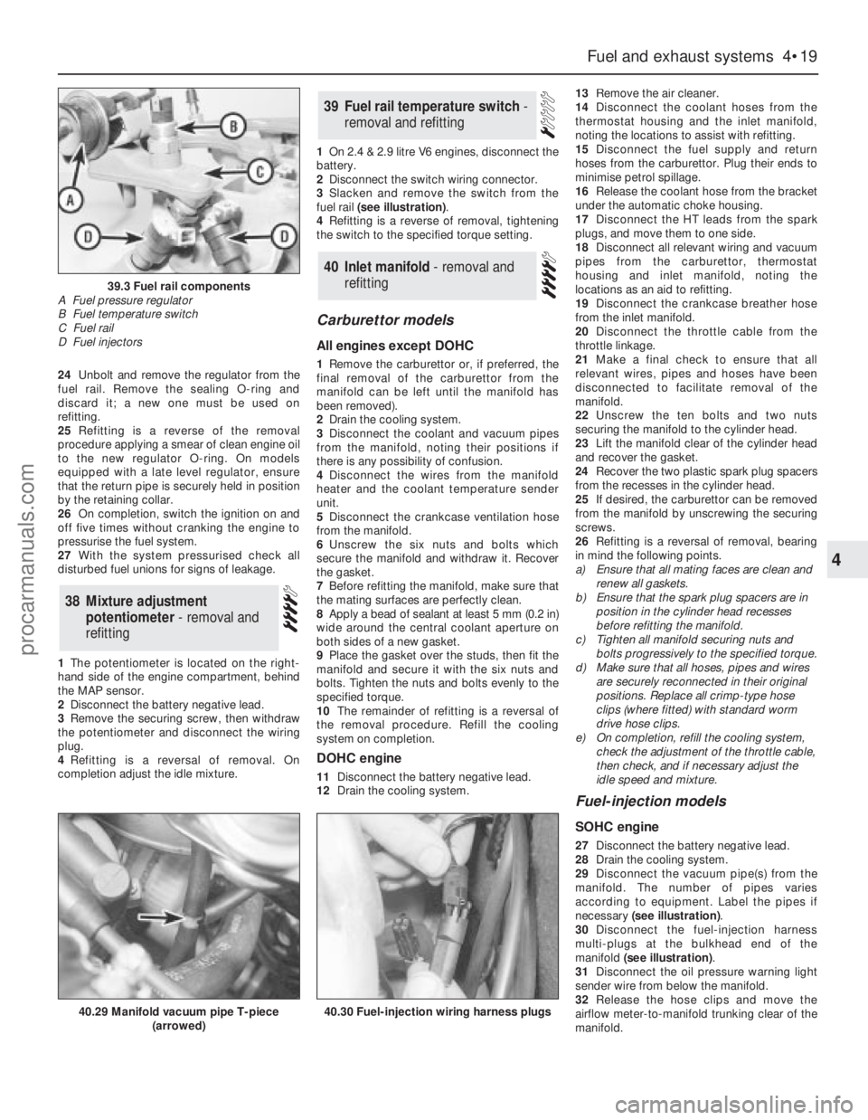
fuel rail (see illustration).
4Refitting is a reverse of removal, tightening
the switch to the specified torque setting.
Carburettor models
All engines except DOHC
1Remove the carburettor or, if preferred, the
final removal of the carburettor from the
manifold can be left until the manifold has
been removed).
2Drain the cooling system.
3Disconnect the coolant and vacuum pipes
from the manifold, noting their positions if
there is any possibility of confusion.
4Disconnect the wires from the manifold
heater and the coolant temperature sender
unit.
5Disconnect the crankcase ventilation hose
from the manifold.
6Unscrew the six nuts and bolts which
secure the manifold and withdraw it. Recover
the gasket.
7Before refitting the manifold, make sure that
the mating surfaces are perfectly clean.
8Apply a bead of sealant at least 5 mm (0.2 in)
wide around the central coolant aperture on
both sides of a new gasket.
9Place the gasket over the studs, then fit the
manifold and secure it with the six nuts and
bolts. Tighten the nuts and bolts evenly to the
specified torque.
10The remainder of refitting is a reversal of
the removal procedure. Refill the cooling
system on completion.
DOHC engine
11Disconnect the battery negative lead.
12Drain the cooling system.13Remove the air cleaner.
14Disconnect the coolant hoses from the
thermostat housing and the inlet manifold,
noting the locations to assist with refitting.
15Disconnect the fuel supply and return
hoses from the carburettor. Plug their ends to
minimise petrol spillage.
16Release the coolant hose from the bracket
under the automatic choke housing.
17Disconnect the HT leads from the spark
plugs, and move them to one side.
18Disconnect all relevant wiring and vacuum
pipes from the carburettor, thermostat
housing and inlet manifold, noting the
locations as an aid to refitting.
19Disconnect the crankcase breather hose
from the inlet manifold.
20Disconnect the throttle cable from the
throttle linkage.
21Make a final check to ensure that all
relevant wires, pipes and hoses have been
disconnected to facilitate removal of the
manifold.
22Unscrew the ten bolts and two nuts
securing the manifold to the cylinder head.
23Lift the manifold clear of the cylinder head
and recover the gasket.
24Recover the two plastic spark plug spacers
from the recesses in the cylinder head.
25If desired, the carburettor can be removed
from the manifold by unscrewing the securing
screws.
26Refitting is a reversal of removal, bearing
in mind the following points.
a)Ensure that all mating faces are clean and
renew all gaskets.
b)Ensure that the spark plug spacers are in
position in the cylinder head recesses
before refitting the manifold.
c)Tighten all manifold securing nuts and
bolts progressively to the specified torque.
d)Make sure that all hoses, pipes and wires
are securely reconnected in their original
positions. Replace all crimp-type hose
clips (where fitted) with standard worm
drive hose clips.
e)On completion, refill the cooling system,
check the adjustment of the throttle cable,
then check, and if necessary adjust the
idle speed and mixture.
Fuel-injection models
SOHC engine
27Disconnect the battery negative lead.
28Drain the cooling system.
29Disconnect the vacuum pipe(s) from the
manifold. The number of pipes varies
according to equipment. Label the pipes if
necessary (see illustration).
30Disconnect the fuel-injection harness
multi-plugs at the bulkhead end of the
manifold (see illustration).
31Disconnect the oil pressure warning light
sender wire from below the manifold.
32Release the hose clips and move the
airflow meter-to-manifold trunking clear of the
manifold.
40Inlet manifold - removal and
refitting
39Fuel rail temperature switch -
removal and refitting
38Mixture adjustment
potentiometer - removal and
refitting
Fuel and exhaust systems 4•19
4
39.3 Fuel rail components
A Fuel pressure regulator
B Fuel temperature switch
C Fuel rail
D Fuel injectors
40.29 Manifold vacuum pipe T-piece
(arrowed)40.30 Fuel-injection wiring harness plugs
procarmanuals.com