1985 FORD GRANADA wheel alignment
[x] Cancel search: wheel alignmentPage 8 of 255
to release any pressure. When pressure has
been released, carry on unscrewing the cap
and remove it.
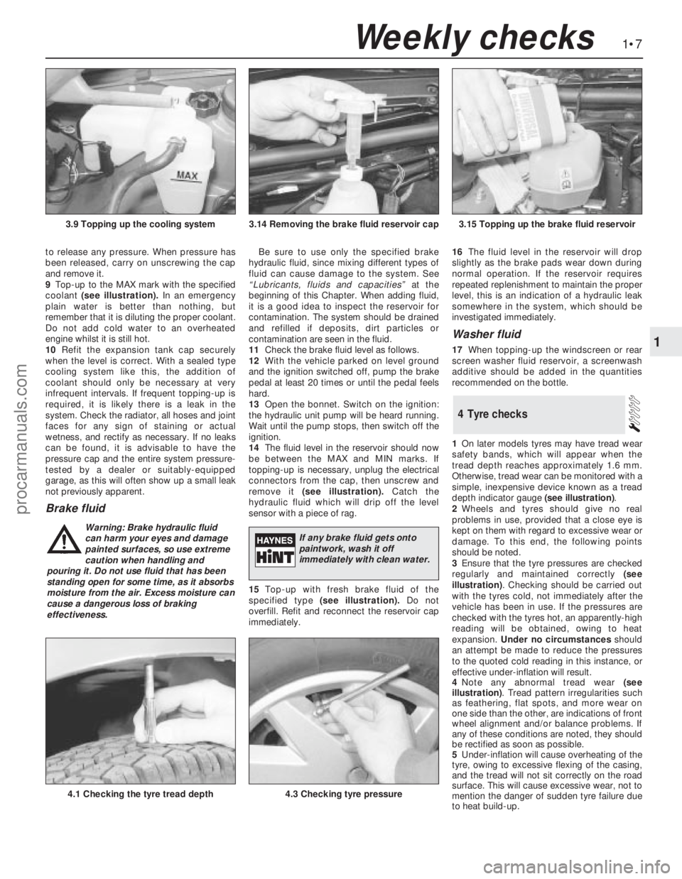
9Top-up to the MAX mark with the specified
coolant (see illustration).In an emergency
plain water is better than nothing, but
remember that it is diluting the proper coolant.
Do not add cold water to an overheated
engine whilst it is still hot.
10Refit the expansion tank cap securely
when the level is correct. With a sealed type
cooling system like this, the addition of
coolant should only be necessary at very
infrequent intervals. If frequent topping-up is
required, it is likely there is a leak in the
system. Check the radiator, all hoses and joint
faces for any sign of staining or actual
wetness, and rectify as necessary. If no leaks
can be found, it is advisable to have the
pressure cap and the entire system pressure-
tested by a dealer or suitably-equipped
garage, as this will often show up a small leak
not previously apparent.
Brake fluid
Be sure to use only the specified brake
hydraulic fluid, since mixing different types of
fluid can cause damage to the system. See
“Lubricants, fluids and capacities”at the
beginning of this Chapter. When adding fluid,
it is a good idea to inspect the reservoir for
contamination. The system should be drained
and refilled if deposits, dirt particles or
contamination are seen in the fluid.
11Check the brake fluid level as follows.
12With the vehicle parked on level ground
and the ignition switched off, pump the brake
pedal at least 20 times or until the pedal feels
hard.
13Open the bonnet. Switch on the ignition:
the hydraulic unit pump will be heard running.
Wait until the pump stops, then switch off the
ignition.
14The fluid level in the reservoir should now
be between the MAX and MIN marks. If
topping-up is necessary, unplug the electrical
connectors from the cap, then unscrew and
remove it (see illustration).Catch the
hydraulic fluid which will drip off the level
sensor with a piece of rag.
15Top-up with fresh brake fluid of the
specified type (see illustration).Do not
overfill. Refit and reconnect the reservoir cap
immediately.16The fluid level in the reservoir will drop
slightly as the brake pads wear down during
normal operation. If the reservoir requires
repeated replenishment to maintain the proper
level, this is an indication of a hydraulic leak
somewhere in the system, which should be
investigated immediately.
Washer fluid
17When topping-up the windscreen or rear
screen washer fluid reservoir, a screenwash
additive should be added in the quantities
recommended on the bottle.
1On later models tyres may have tread wear
safety bands, which will appear when the
tread depth reaches approximately 1.6 mm.
Otherwise, tread wear can be monitored with a
simple, inexpensive device known as a tread
depth indicator gauge (see illustration).
2Wheels and tyres should give no real
problems in use, provided that a close eye is
kept on them with regard to excessive wear or
damage. To this end, the following points
should be noted.
3Ensure that the tyre pressures are checked
regularly and maintained correctly (see
illustration). Checking should be carried out
with the tyres cold, not immediately after the
vehicle has been in use. If the pressures are
checked with the tyres hot, an apparently-high
reading will be obtained, owing to heat
expansion. Under no circumstancesshould
an attempt be made to reduce the pressures
to the quoted cold reading in this instance, or
effective under-inflation will result.
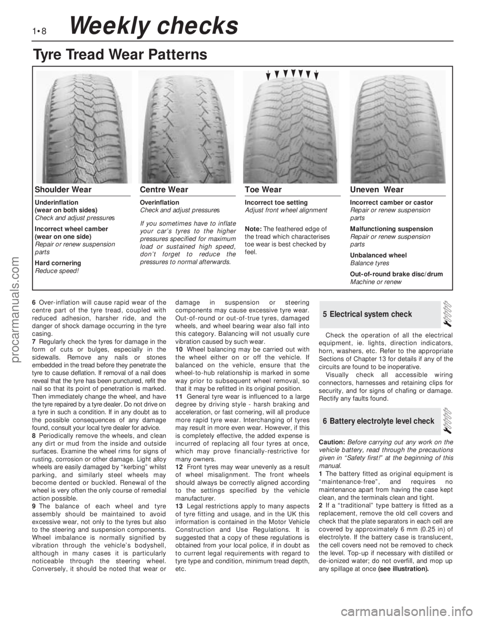
4Note any abnormal tread wear (see
illustration). Tread pattern irregularities such
as feathering, flat spots, and more wear on
one side than the other, are indications of front
wheel alignment and/or balance problems. If
any of these conditions are noted, they should
be rectified as soon as possible.
5Under-inflation will cause overheating of the
tyre, owing to excessive flexing of the casing,
and the tread will not sit correctly on the road
surface. This will cause excessive wear, not to
mention the danger of sudden tyre failure due
to heat build-up.
4Tyre checks
1•7
1
Weekly checks
3.14 Removing the brake fluid reservoir cap3.15 Topping up the brake fluid reservoir
4.1 Checking the tyre tread depth4.3 Checking tyre pressure
3.9 Topping up the cooling system
Warning: Brake hydraulic fluid
can harm your eyes and damage
painted surfaces, so use extreme
caution when handling and
pouring it. Do not use fluid that has been
standing open for some time, as it absorbs
moisture from the air. Excess moisture can
cause a dangerous loss of braking
effectiveness.If any brake fluid gets onto
paintwork, wash it off
immediately with clean water.
procarmanuals.com
Page 9 of 255
6Over-inflation will cause rapid wear of the
centre part of the tyre tread, coupled with
reduced adhesion, harsher ride, and the
danger of shock damage occurring in the tyre
casing.
7Regularly check the tyres for damage in the
form of cuts or bulges, especially in the
sidewalls. Remove any nails or stones
embedded in the tread before they penetrate the
tyre to cause deflation. If removal of a nail does
reveal that the tyre has been punctured, refit the
nail so that its point of penetration is marked.
Then immediately change the wheel, and have
the tyre repaired by a tyre dealer. Do not drive on
a tyre in such a condition. If in any doubt as to
the possible consequences of any damage
found, consult your local tyre dealer for advice.
8Periodically remove the wheels, and clean
any dirt or mud from the inside and outside
surfaces. Examine the wheel rims for signs of
rusting, corrosion or other damage. Light alloy
wheels are easily damaged by “kerbing” whilst
parking, and similarly steel wheels may
become dented or buckled. Renewal of the
wheel is very often the only course of remedial
action possible.
9The balance of each wheel and tyre
assembly should be maintained to avoid
excessive wear, not only to the tyres but also
to the steering and suspension components.
Wheel imbalance is normally signified by
vibration through the vehicle’s bodyshell,
although in many cases it is particularly
noticeable through the steering wheel.
Conversely, it should be noted that wear ordamage in suspension or steering
components may cause excessive tyre wear.
Out-of-round or out-of-true tyres, damaged
wheels, and wheel bearing wear also fall into
this category. Balancing will not usually cure
vibration caused by such wear.
10Wheel balancing may be carried out with
the wheel either on or off the vehicle. If
balanced on the vehicle, ensure that the
wheel-to-hub relationship is marked in some
way prior to subsequent wheel removal, so
that it may be refitted in its original position.
11General tyre wear is influenced to a large
degree by driving style - harsh braking and
acceleration, or fast cornering, will all produce
more rapid tyre wear. Interchanging of tyres
may result in more even wear. However, if this
is completely effective, the added expense is
incurred of replacing all four tyres at once,
which may prove financially-restrictive for
many owners.
12Front tyres may wear unevenly as a result
of wheel misalignment. The front wheels
should always be correctly aligned according
to the settings specified by the vehicle
manufacturer.
13Legal restrictions apply to many aspects
of tyre fitting and usage, and in the UK this
information is contained in the Motor Vehicle
Construction and Use Regulations. It is
suggested that a copy of these regulations is
obtained from your local police, if in doubt as
to current legal requirements with regard to
tyre type and condition, minimum tread depth,
etc.Check the operation of all the electrical
equipment, ie. lights, direction indicators,
horn, washers, etc. Refer to the appropriate
Sections of Chapter 13 for details if any of the
circuits are found to be inoperative.
Visually check all accessible wiring
connectors, harnesses and retaining clips for
security, and for signs of chafing or damage.
Rectify any faults found.
Caution: Before carrying out any work on the
vehicle battery, read through the precautions
given in “Safety first!” at the beginning of this
manual.
1The battery fitted as original equipment is
“maintenance-free”, and requires no
maintenance apart from having the case kept
clean, and the terminals clean and tight.
2If a “traditional” type battery is fitted as a
replacement, remove the old cell covers and
check that the plate separators in each cell are
covered by approximately 6 mm (0.25 in) of
electrolyte. If the battery case is translucent,
the cell covers need not be removed to check
the level. Top-up if necessary with distilled or
de-ionized water; do not overfill, and mop up
any spillage at once(see illustration).
6Battery electrolyte level check
5Electrical system check
1•8Weekly checks
Tyre Tread Wear Patterns
Shoulder Wear
Underinflation
(wear on both sides)
Check and adjust pressures
Incorrect wheel camber
(wear on one side)
Repair or renew suspension
parts
Hard cornering
Reduce speed!
Centre Wear
Overinflation
Check and adjust pressures
If you sometimes have to inflate
your car’s tyres to the higher
pressures specified for maximum
load or sustained high speed,
don’t forget to reduce the
pressures to normal afterwards.
Toe Wear
Incorrect toe setting
Adjust front wheel alignment
Note: The feathered edge of
the tread which characterises
toe wear is best checked by
feel.
Uneven Wear
Incorrect camber or castor
Repair or renew suspension
parts
Malfunctioning suspension
Repair or renew suspension
parts
Unbalanced wheel
Balance tyres
Out-of-round brake disc/drum
Machine or renew
procarmanuals.com
Page 33 of 255
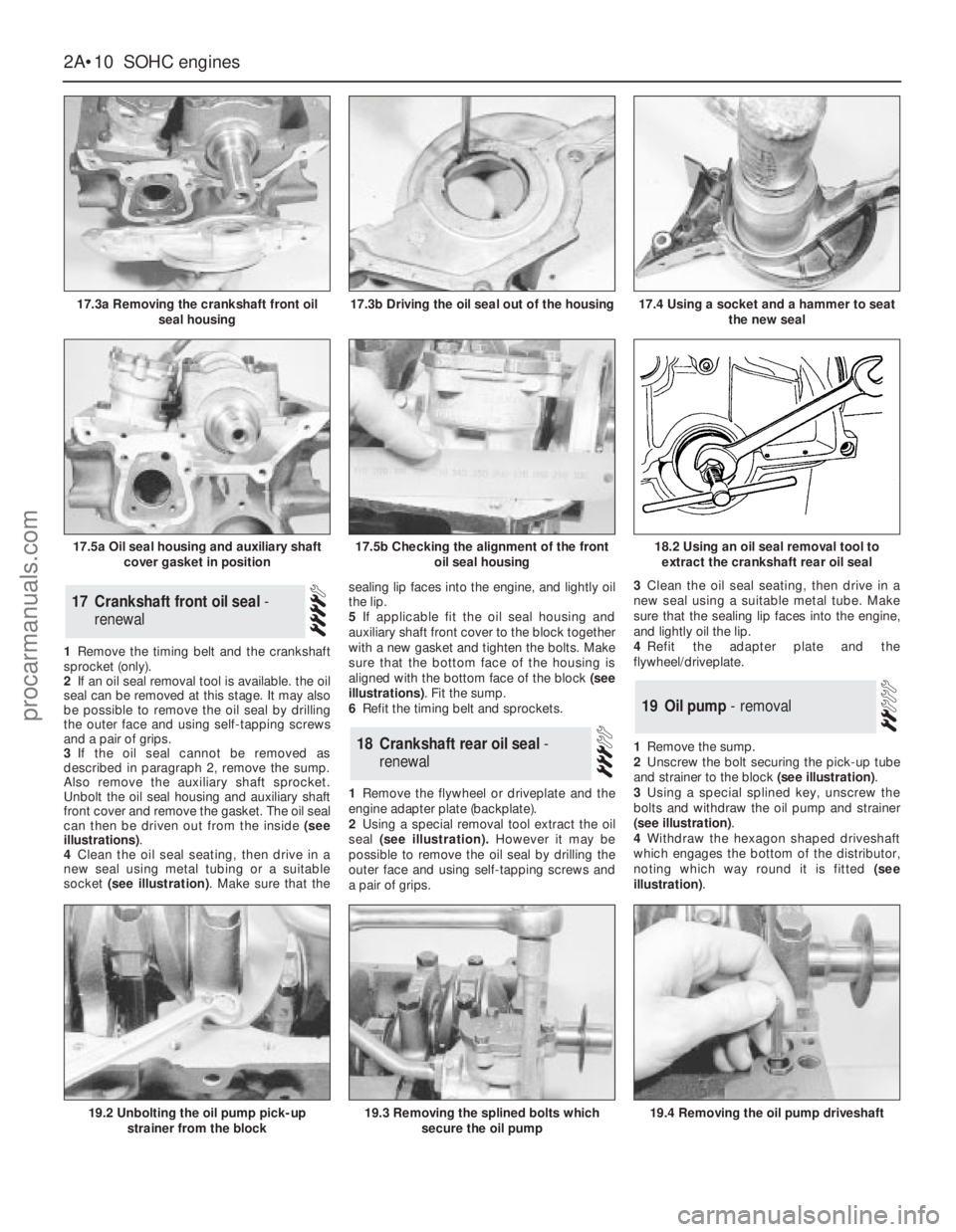
1Remove the timing belt and the crankshaft
sprocket (only).
2If an oil seal removal tool is available. the oil
seal can be removed at this stage. It may also
be possible to remove the oil seal by drilling
the outer face and using self-tapping screws
and a pair of grips.
3If the oil seal cannot be removed as
described in paragraph 2, remove the sump.
Also remove the auxiliary shaft sprocket.
Unbolt the oil seal housing and auxiliary shaft
front cover and remove the gasket. The oil seal
can then be driven out from the inside (see
illustrations).
4Clean the oil seal seating, then drive in a
new seal using metal tubing or a suitable
socket (see illustration). Make sure that thesealing lip faces into the engine, and lightly oil
the lip.
5If applicable fit the oil seal housing and
auxiliary shaft front cover to the block together
with a new gasket and tighten the bolts. Make
sure that the bottom face of the housing is
aligned with the bottom face of the block (see
illustrations). Fit the sump.
6Refit the timing belt and sprockets.
1Remove the flywheel or driveplate and the
engine adapter plate (backplate).
2Using a special removal tool extract the oil
seal (see illustration).However it may be
possible to remove the oil seal by drilling the
outer face and using self-tapping screws and
a pair of grips.3Clean the oil seal seating, then drive in a
new seal using a suitable metal tube. Make
sure that the sealing lip faces into the engine,
and lightly oil the lip.
4Refit the adapter plate and the
flywheel/driveplate.
1Remove the sump.
2Unscrew the bolt securing the pick-up tube
and strainer to the block (see illustration).
3Using a special splined key, unscrew the
bolts and withdraw the oil pump and strainer
(see illustration).
4Withdraw the hexagon shaped driveshaft
which engages the bottom of the distributor,
noting which way round it is fitted (see
illustration).
19Oil pump - removal
18Crankshaft rear oil seal -
renewal
17Crankshaft front oil seal -
renewal
2A•10SOHCengines
17.3a Removing the crankshaft front oil
seal housing
19.2 Unbolting the oil pump pick-up
strainer from the block19.3 Removing the splined bolts which
secure the oil pump19.4 Removing the oil pump driveshaft
18.2 Using an oil seal removal tool to
extract the crankshaft rear oil seal
17.3b Driving the oil seal out of the housing
17.5a Oil seal housing and auxiliary shaft
cover gasket in position17.5b Checking the alignment of the front
oil seal housing
17.4 Using a socket and a hammer to seat
the new seal
procarmanuals.com
Page 48 of 255
27Remove the starter motor.
28Remove the exhaust downpipe.
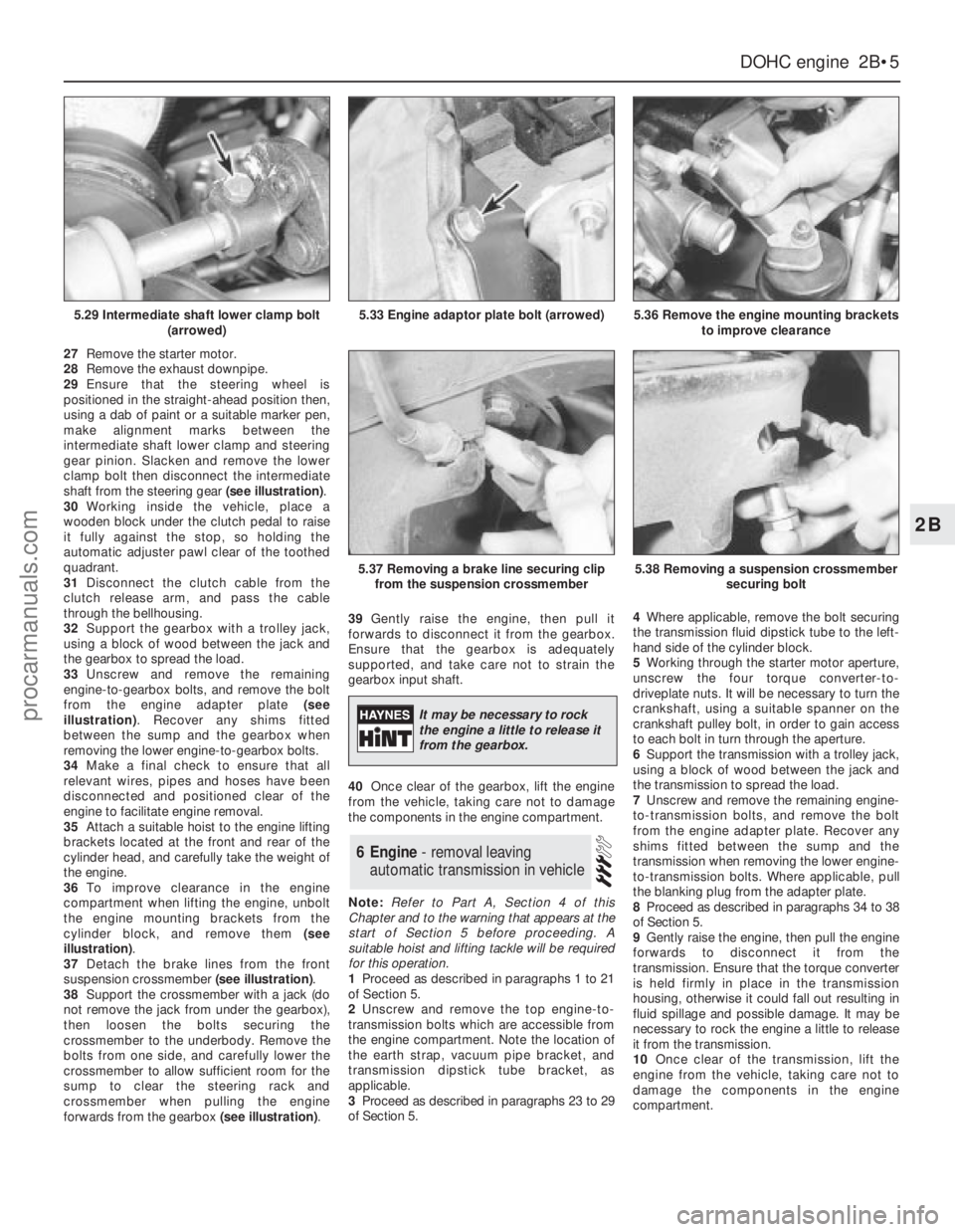
29Ensure that the steering wheel is
positioned in the straight-ahead position then,
using a dab of paint or a suitable marker pen,
make alignment marks between the
intermediate shaft lower clamp and steering
gear pinion. Slacken and remove the lower
clamp bolt then disconnect the intermediate
shaft from the steering gear (see illustration).
30Working inside the vehicle, place a
wooden block under the clutch pedal to raise
it fully against the stop, so holding the
automatic adjuster pawl clear of the toothed
quadrant.
31Disconnect the clutch cable from the
clutch release arm, and pass the cable
through the bellhousing.
32Support the gearbox with a trolley jack,
using a block of wood between the jack and
the gearbox to spread the load.
33Unscrew and remove the remaining
engine-to-gearbox bolts, and remove the bolt
from the engine adapter plate (see
illustration). Recover any shims fitted
between the sump and the gearbox when
removing the lower engine-to-gearbox bolts.
34Make a final check to ensure that all
relevant wires, pipes and hoses have been
disconnected and positioned clear of the
engine to facilitate engine removal.
35Attach a suitable hoist to the engine lifting
brackets located at the front and rear of the
cylinder head, and carefully take the weight of
the engine.
36To improve clearance in the engine
compartment when lifting the engine, unbolt
the engine mounting brackets from the
cylinder block, and remove them (see
illustration).
37Detach the brake lines from the front
suspension crossmember (see illustration).
38Support the crossmember with a jack (do
not remove the jack from under the gearbox),
then loosen the bolts securing the
crossmember to the underbody. Remove the
bolts from one side, and carefully lower the
crossmember to allow sufficient room for the
sump to clear the steering rack and
crossmember when pulling the engine
forwards from the gearbox (see illustration).39Gently raise the engine, then pull it
forwards to disconnect it from the gearbox.
Ensure that the gearbox is adequately
supported, and take care not to strain the
gearbox input shaft.
40Once clear of the gearbox, lift the engine
from the vehicle, taking care not to damage
the components in the engine compartment.
Note:Refer to Part A, Section 4 of this
Chapter and to the warning that appears at the
start of Section 5 before proceeding. A
suitable hoist and lifting tackle will be required
for this operation.
1Proceed as described in paragraphs 1 to 21
of Section 5.
2Unscrew and remove the top engine-to-
transmission bolts which are accessible from
the engine compartment. Note the location of
the earth strap, vacuum pipe bracket, and
transmission dipstick tube bracket, as
applicable.
3Proceed as described in paragraphs 23 to 29
of Section 5.4Where applicable, remove the bolt securing
the transmission fluid dipstick tube to the left-
hand side of the cylinder block.
5Working through the starter motor aperture,
unscrew the four torque converter-to-
driveplate nuts. It will be necessary to turn the
crankshaft, using a suitable spanner on the
crankshaft pulley bolt, in order to gain access
to each bolt in turn through the aperture.
6Support the transmission with a trolley jack,
using a block of wood between the jack and
the transmission to spread the load.
7Unscrew and remove the remaining engine-
to-transmission bolts, and remove the bolt
from the engine adapter plate. Recover any
shims fitted between the sump and the
transmission when removing the lower engine-
to-transmission bolts. Where applicable, pull
the blanking plug from the adapter plate.
8Proceed as described in paragraphs 34 to 38
of Section 5.
9Gently raise the engine, then pull the engine
forwards to disconnect it from the
transmission. Ensure that the torque converter
is held firmly in place in the transmission
housing, otherwise it could fall out resulting in
fluid spillage and possible damage. It may be
necessary to rock the engine a little to release
it from the transmission.
10Once clear of the transmission, lift the
engine from the vehicle, taking care not to
damage the components in the engine
compartment.
6Engine - removal leaving
automatic transmission in vehicle
DOHCengine 2B•5
2B
5.29 Intermediate shaft lower clamp bolt
(arrowed)5.33 Engine adaptor plate bolt (arrowed)5.36 Remove the engine mounting brackets
to improve clearance
5.37 Removing a brake line securing clip
from the suspension crossmember5.38 Removing a suspension crossmember
securing bolt
It may be necessary to rock
the engine a little to release it
from the gearbox.
procarmanuals.com
Page 49 of 255
Note: Refer to Part A, Section 4 of this Chapter
and to the warning that appears at the start of
Section 5 before proceeding. A hoist and lifting
tackle will be required for this operation.
1Proceed as described in paragraphs 1 to 21
of Section 5.
2Unscrew the securing bolt, and disconnect
the earth lead from the rear left-hand side of
the cylinder head.
3Unscrew the nuts securing the engine
mountings to the engine mounting brackets.
4Jack up the vehicle and support it securely
on axle stands (see “Jacking”). Ensure that
there is enough working room beneath the
vehicle.
5To improve access, disconnect the exhaust
downpipe from the manifold and remove the
exhaust system.
6Drain the engine oil into a suitable container.
7On models fitted with a catalytic converter,
release the securing clips and withdraw the
exhaust heat shield from under the vehicle for
access to the propeller shaft.
8Remove the propeller shaft.
9Where applicable, bend back the locktabs,
then unscrew the two bolts in each case
securing the two anti-roll bar mounting clamps
to the vehicle underbody. Lower the anti-roll
bar as far as possible.
10Proceed as described in paragraphs 30
and 31 of Section 5.
11Support the gearbox with a trolley jack,
using a block of wood between the jack and
the gearbox to spread the load.
12Unscrew the four nuts securing the
gearbox crossmember to the vehicle
underbody. Unscrew the central bolt securing
the crossmember to the gearbox, and remove
the crossmember. Note the position of the
earth strap, where applicable. Recover the
mounting cup, and the exhaust mounting
bracket and heat shield (as applicable).
13Lower the gearbox slightly on the jack,
then remove the circlip, and disconnect the
speedometer drive cable from the gearbox.
14Disconnect the wiring from the reversing
lamp switch, and on models with fuel-injection,
disconnect the wiring from the vehicle speed
sensor mounted in the side of the gearbox.
15Slacken and remove the two bolts and
washers (one either side) securing the gear
linkage support bracket to the gearbox.
16Using a pin punch, drive out the roll pin
securing the gearchange rod to the gear linkage.
17Attach a hoist to the engine lifting brackets
located at the front and rear of the cylinder head,
and slowly take the weight of the engine. Arrange
the lifting tackle so that the engine/gearbox
assembly will assume a steep angle of
approximately 40°to 45°as it is being removed.
18To improve clearance in the engine
compartment when lifting the engine, unboltthe engine mounting brackets from the
cylinder block, and remove them.
19Ensure that the steering wheel is positioned
in the straight-ahead position then, using a dab
of paint or a marker pen, make alignment marks
between the intermediate shaft lower clamp
and steering gear pinion. Slacken and remove
the lower clamp bolt then disconnect the
intermediate shaft from the steering gear.
20Detach the brake lines from the front
suspension crossmember.
21Support the crossmember with a jack (do not
remove the jack from under the gearbox), then
loosen the bolts securing the crossmember to the
underbody. Remove the crossmember securing
bolts, and carefully lower the crossmember to
allow sufficient room for the engine sump to clear
the steering rack and crossmember as the
engine/gearbox assembly is removed.
22Make a final check to ensure that all
relevant wires, pipes and hoses have been
disconnected to facilitate removal of the
engine/gearbox assembly.
23Raise the engine/gearbox, at the same
time lowering the trolley jack which is
supporting the gearbox.
24Place a suitable rod across the vehicle
underbody to support the gear linkage support
bracket whilst the gearbox is removed.
25Tilt the engine/gearbox assembly using
the hoist and the trolley jack, until the
assembly can be lifted from the vehicle. Take
care not to damage surrounding components.
26If the vehicle is to be moved, with the
engine/gearbox assembly removed, temporarily
refit the suspension crossmember and the anti-
roll bar to the underbody, and reconnect the
steering column to the intermediate shaft.
27To separate the engine from the gearbox,
proceed as follows.
28Remove the starter motor.
29Support the engine and gearbox
horizontally on blocks of wood.
30Unscrew the engine-to-gearbox bolts,
noting the locations of the bolts, and the
positions of the earth strap and any wiring clips
attached to the bolts. Recover any shims fitted
between the sump and the gearbox when
removing the lower engine-to-gearbox bolts.
31Unscrew the bolt from the engine adapter
plate.
32Pull the engine and gearbox apart, taking
care not to strain the gearbox input shaft. It
may be necessary to rock the units slightly to
separate them.
Note: Refer to Part A, Section 4 of this
Chapter and to the warning that appears at the
start of Section 5 before proceeding. A
suitable hoist and lifting tackle will be required
for this operation. Any suspected faults in the
automatic transmission should be referred to a
Ford dealer or automatic transmissionspecialist before removal of unit, as the
specialist fault diagnosis equipment is
designed to operate with the transmission in
the vehicle.
1Proceed as described in paragraphs 1 to 21
of Section 5.
2Unscrew the securing bolt, and disconnect
the earth lead from the rear left-hand side of
the cylinder head.
3Unscrew the nuts securing the engine
mountings to the engine mounting brackets.
4Jack up the vehicle and support it securely
on axle stands (see “Jacking”). Ensure that
there is enough working room beneath the
vehicle.
5To improve access, disconnect the exhaust
downpipe from the manifold and remove the
exhaust system .
6Drain the engine oil into a suitable container.
7On models fitted with a catalytic converter,
release the securing clips and withdraw the
exhaust heat shield from under the vehicle for
access to the propeller shaft.
8Remove the propeller shaft.
9Where applicable, bend back the locktabs,
then unscrew the two bolts in each case
securing the two anti-roll bar mounting clamps
to the vehicle underbody. Lower the anti-roll
bar as far as possible.
10Support the transmission with a trolley
jack, using a block of wood between the jack
and the transmission to spread the load.
11Unscrew the four bolts securing the
transmission crossmember to the vehicle
underbody. Unscrew the central bolt securing
the crossmember to the transmission, and
remove the crossmember. Note the position of
the earth strap, where applicable. Recover the
mounting cup, and the exhaust mounting
bracket and heat shield (as applicable).
12Lower the transmission slightly on the jack.
13Unscrew the unions and disconnect the
fluid cooler pipes from the transmission. Plug
the open ends of the pipes and the
transmission to prevent dirt ingress and fluid
leakage. Where applicable, detach the fluid
cooler pipe bracket from the engine mounting
bracket, and move it to one side.
14Remove the two clips securing the
selector rod, and detach the selector rod from
the manual selector lever, and the selector
lever on the transmission.
15Disconnect the wiring from the starter
inhibitor switch, downshift solenoid, lock-up
clutch, reversing lamp switch, and where
applicable, the 3rd/4th gearchange solenoid.
16Remove the securing screw, and
disconnect the speedometer cable (where
fitted) from the transmission extension
housing. Plug the opening in the transmission
to prevent dirt ingress.
17Proceed as described in paragraphs 17 to 26
of Section 7, substituting transmission for
gearbox and ignoring paragraph 24.
18To separate the engine from the
transmission, proceed as follows.
19Remove the starter motor.
20Support the engine and transmission
horizontally on blocks of wood.
8Engine/automatic
transmission assembly -
removal and separation
7Engine/manual gearbox
assembly - removal and
separation
2B•6DOHCengine
procarmanuals.com
Page 58 of 255
d)Disconnect the breather hose from the
camshaft cover.
e)Remove the distributor cap and HT leads,
and the rotor arm and housing. If
necessary, mark the HT leads to aid
refitting.
2Proceed as described in paragraphs 2 to 15
inclusive of Section 18.
3Examine the surfaces of the camshaft
journals and lobes and the contact surfaces of
the cam followers for wear. If wear is
excessive, considerable noise would have
been noticed from the top of the engine when
running, and new camshafts and followers
must be fitted. It is unlikely that this level of
wear will occur unless a considerable mileage
has been covered. Note that the cam followers
cannot be dismantled for renewal of individual
components.
4Check the camshaft bearing surfaces in the
cylinder head and the bearing caps for wear. If
excessive wear is evident, the only course of
action available is to renew the cylinder head
complete with bearing caps.
5Check the cam follower bores in the
cylinder head for wear. If excessive wear is
evident, the cylinder head must be renewed.
6Check the cam follower oil grooves and the
oil ports in the cylinder head for obstructions.
7Refit the cam followers and the camshafts as
described in paragraphs 27 to 55 of Section 18.
8If the engine is in the vehicle, reverse the
operations given in paragraph 1.
Refer to Part A, Section 15 of this Chapter,
noting the following points.
a)If the engine is in the car, refer to Chapter
6 when removing and refitting the clutch,
where applicable.
b)The flywheel/driveplate securing bolts
must be renewed on refitting; the new
bolts are supplied ready-coated with
thread-locking compound (see
illustration).
c)Check on the availability of new parts
before contemplating renewal of the ring
gear.Note: A suitable puller will be required to
remove the crankshaft pulley. A new
crankshaft pulley bolt and a new lower timing
chain cover gasket must be used on refitting.
1The crankshaft front oil seal is located in the
lower timing chain cover.
2If the engine is in the car, carry out the
following operations.
a)Disconnect the battery negative lead.
b)To improve access, remove the radiator. It
will be difficult to remove the crankshaft
pulley with the radiator in place.
c)On fuel-injection models, remove the air
inlet hose, plenum chamber, and air
cleaner lid as an assembly.
3Proceed as described in paragraphs 3 to 8
of Section 15.
4With the lower timing chain cover removed,
prise the old oil seal from the cover using a
screwdriver, and drive in the new seal using a
suitable metal tube. Make sure that the seal lip
faces into the engine. Take care not to
damage the timing chain cover. Note that the
seal should be fitted dry.
5Refit the lower timing chain cover as
described in paragraphs 32 to 40 of Section 15.
6If the engine is in the vehicle, reverse the
operations given in paragraph 2.
Note: New flywheel/driveplate bolts must be
used on refitting.
1Remove the flywheel/driveplate and the
engine adapter plate.
2Extract the seal using an oil seal removal tool
if available. It may also be possible to remove
the oil seal by drilling the outer face and using
self-tapping screws and a pair of grips.
3Clean the oil seal housing, then carefully
wind a thin layer of tape around the edge of
the crankshaft to protect the oil seal lip as the
seal is installed.
4Install a new oil seal. Make sure that the seal
lip faces into the engine (see illustration).5With the oil seal installed, carefully pull the
tape from the edge of the crankshaft.
6Refit the engine adapter plate and the
flywheel/driveplate.
Note: A new sump gasket will be required on
refitting, and suitable sealing compound will
be required to coat the sump and cylinder
block mating faces. Shims may be required
when mating the gearbox/transmission.
1Sump removal and refitting is far easier if
the engine is removed from the vehicle,
however if the engine is in the vehicle, proceed
as follows. If the engine has been removed
from the vehicle, proceed to paragraph 9.
2Remove the clutch or automatic
transmission, as applicable.
3Remove the flywheel/driveplate and the
engine adapter plate.
4Drain the engine oil into a suitable container.
5Ensure that the steering wheel is positioned
in the straight-ahead position then, using a
dab of paint or a marker pen, make alignment
marks between the intermediate shaft lower
clamp and steering gear pinion. Slacken and
remove the lower clamp bolt then disconnect
the intermediate shaft from the steering gear.
6Attach a suitable hoist to the engine lifting
brackets located at the front and rear of the
cylinder head, and carefully take the weight of
the engine.
7Detach the brake lines from the front
suspension crossmember.
8Support the crossmember with a jack, then
loosen the bolts securing the crossmember to
the underbody. Remove the bolts and carefully
lower the crossmember sufficiently to allow
the sump to be removed.
9If the engine has been removed, it is
preferable to keep it upright until the sump has
been removed to prevent sludge from entering
the engine internals.
10Unscrew the sump securing nuts and
bolts, and withdraw the sump from the engine.
Do not prise between the mating faces of the
sump and cylinder block. Discard the old
gasket.
11Thoroughly clean the mating faces of the
cylinder block and sump.
12Commence refitting by locating a new
gasket in the grooves in the sump.
25Sump - removal and refitting
24Crankshaft rear oil seal -
renewal
23Crankshaft front oil seal -
renewal
22Flywheel/driveplate - removal
inspection and refitting
DOHCengine 2B•15
2B
22.1 Improvised tool used to hold flywheel
when tightening securing bolts
24.4 Tool used to fit the oil seal
A Rear oil seal housing
B Special tool
A tool can be improvised using
a metal tube, a metal disc or
flat bar, and two flywheel
bolts.Draw the seal into
position using the two flywheel bolts.
If the sump is stuck, gently
tap it sideways to free it (the
sump will not move far
sideways, as it locates on
studs in the cylinder block).
procarmanuals.com
Page 72 of 255
from the top of the engine mounting brackets
(see illustrations).
29Drain the engine oil, retaining it for further
use only if it is not contaminated or due for
renewal.
30Unbolt the coolant distribution pipe bracket
from the timing cover (see illustration).
31Disconnect the leads and remove the
starter motor.
32Ensure that the front roadwheels and the
steering wheels are in the straight-ahead
position, then remove the pinch-bolt from the
steering shaft coupling and slide the coupling
down the shaft (see illustration).
33Unscrew the sump retaining nuts and
bolts. The rear bolts can only be unscrewed
using a box spanner or thin-walled socket.
34Release the brake hydraulic lines from
their support brackets by pulling out their
retaining clips.
35Unscrew the two bolts from each of the
crossmember side brackets. Lower the
crossmember just enough to be able to
remove the sump. In practice, as the car is
standing on its roadwheels, the car body
should be raised by placing two axle stands
under the front jacking points (see
illustration).
36Extract the nine bolts and remove the
timing cover complete with water pump (see
illustration). Removal of the radiator grille will
provide better access to the cover bolts.
37Check that the crankshaft and camshaft
sprocket timing marks are aligned at the
nearest point to each other (see illustration).If not, turn the crankshaft as necessary.
38Unbolt and remove the timing chain
tensioner. Take care not to allow the spring-
loaded tensioner plunger to eject (see
illustration).
39Lock the camshaft sprocket by passing a
rod through one of the holes and unscrew the
sprocket retaining bolt (see illustration).
40Remove the camshaft sprocket then
release the chain from the crankshaft sprocket
and remove the camshaft sprocket and chain
from the engine.
41If required, the crankshaft sprocket, Woodruff
key and chain guide can now be also removed.
42Clean away all old pieces of gasket from
the cylinder block and timing cover flanges.
43Remove and discard the sump gasket.
The gasket rear tabs may break off, so pickthem out of the recesses in the rear main
bearing cap using a sharp, pointed knife.
Refer to Part A, Section 15 of this Chapter.
2.8 litre engine
1Remove the sump.
2Remove the two securing bolts and remove
the oil pump complete with pick-up and
strainer.
12Oil pump - removal
11Flywheel/driveplate and
adapter plate - removal
V6 engines 2C•11
2C
10.28b Engine mounting top nut10.30 Coolant distribution pipe bracket10.32 Steering shaft coupling pinch bolt
10.37 Timing sprocket alignment marks
(arrowed)
10.36 Removing a timing cover retaining
bolt10.35 Unscrewing crossmember side
bracket mounting bolts
10.38 Timing chain tensioner assembly10.39 Slackening camshaft sprocket
retaining bolt
procarmanuals.com
Page 140 of 255
5Unscrew the hose from its union on the
caliper and remove it (see illustration).
6Refit by reversing the removal operations,
then bleed the appropriate part of the
hydraulic system (Section 2). In the case of the
front hoses, check that they are not kinked or
twisted, and that they do not contact other
components when the steering is moved from
lock to lock. Reposition the hose in the
bracket if necessary.
7To remove a rigid pipe, simply undo the
union nuts at the hydraulic unit, hose bracket
or T-piece (see illustration). Free the pipe
from any retaining clips and remove it.
8New pipes can be bought ready-made, with
the unions attached. Some garages and motor
factors will make up pipes to order, using the
old pipe as a pattern. If purchasing proprietary
pipes made of copper alloy or similar material,
follow the manufacturer’s instructions carefully
concerning bending, provision of extra clips
etc.
9Fit and secure the new pipe and tighten the
union nuts, bleed the appropriate part of the
hydraulic system (Section 2).
1The handbrake is normally self-adjusting in
use. Adjustment may be required to
compensate for cable stretch over a long
period, and is also necessary after fitting a
new cable.2Chock the front wheels, release the
handbrake and raise and support the rear of
the vehicle.
3Release the adjuster locknut from the
adjuster nut. Back off the adjuster nut,
slackening the cable until both handbrake
levers on the calipers are resting against their
stops (see illustration).
4Paint alignment marks between each
handbrake lever and the caliper body (see
illustration).
5Tighten the adjuster nut until either
handbrake lever just starts to move - as shown
by the alignment marks.
6Apply the handbrake and release it a few
times to equalise the cable runs.
7Tighten the locknut onto the adjuster nut
finger tight, then tighten a further three to six
clicks using self-locking pliers or a peg
spanner.
1Slacken the rear wheel nuts and chock the
front wheels. Raise and support the rear of the
vehicle and remove both rear wheels. Release
the handbrake.
2Slacken off the handbrake cable adjuster
locknut and adjuster nut.
3Free the cable from the equaliser yoke by
removing the circlip and clevis pin (see
illustration). Beware of self-tapping screws
protruding through the floor in this area.4Unhook the cable inner from the handbrake
levers on the calipers. Free the cable outer
from the caliper brackets (see illustration).
5Free the cable from the lower arm and
underbody brackets and remove it.
6Refit by reversing the removal operations,
but before refitting the rear wheels, adjust the
cable as described in the previous Section.
1Chock the front wheels and release the
handbrake. Raise and support the rear of the
vehicle.
2Disconnect the battery negative lead.
3Disconnect the handbrake cable equaliser
yoke by removing the circlip and clevis pin.
4Remove the centre console (Chapter 12).
5Remove the handbrake control lever boot.
6Disconnect the wiring from the handbrake
warning switch.
7Unbolt the handbrake lever and remove it,
complete with switch. Remove the switch if
necessary.
8Refit by reversing the removal operations.
1Remove the under-dash trim on the
passenger’s side.
2Push the module upwards and then swing it
forwards to release it from its clip.
25ABS module - removal and
refitting
24Handbrake control lever -
removal and refitting
23Handbrake cable - removal
and refitting
22Handbrake cable - adjustment
Braking system 10•11
10
21.5 Disconnecting the hose from the
caliper21.7 Brake pipe union T-piece (arrowed)22.3 Handbrake cable adjuster
Locknut previously backed off adjuster nut
22.4 Alignment marks painted on lever and
body23.3 Circlip (arrowed) on equaliser yoke
Note protruding screws in transmission tunnel23.4 Handbrake cable outer attached to
caliper bracket
procarmanuals.com