Page 73 of 255
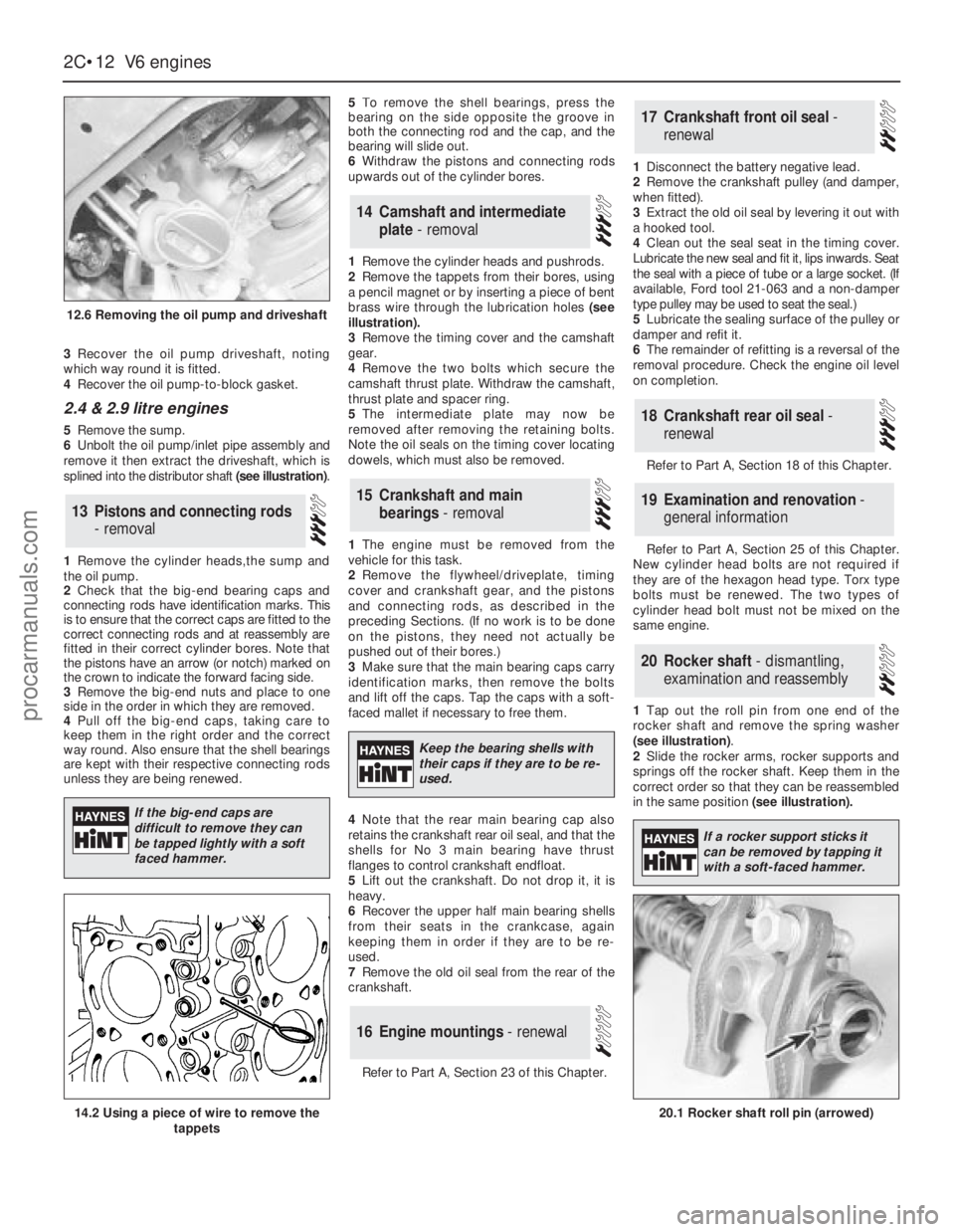
3Recover the oil pump driveshaft, noting
which way round it is fitted.
4Recover the oil pump-to-block gasket.
2.4 & 2.9 litre engines
5Remove the sump.
6Unbolt the oil pump/inlet pipe assembly and
remove it then extract the driveshaft, which is
splined into the distributor shaft (see illustration).
1Remove the cylinder heads,the sump and
the oil pump.
2Check that the big-end bearing caps and
connecting rods have identification marks. This
is to ensure that the correct caps are fitted to the
correct connecting rods and at reassembly are
fitted in their correct cylinder bores. Note that
the pistons have an arrow (or notch) marked on
the crown to indicate the forward facing side.
3Remove the big-end nuts and place to one
side in the order in which they are removed.
4Pull off the big-end caps, taking care to
keep them in the right order and the correct
way round. Also ensure that the shell bearings
are kept with their respective connecting rods
unless they are being renewed.5To remove the shell bearings, press the
bearing on the side opposite the groove in
both the connecting rod and the cap, and the
bearing will slide out.
6Withdraw the pistons and connecting rods
upwards out of the cylinder bores.
1Remove the cylinder heads and pushrods.
2Remove the tappets from their bores, using
a pencil magnet or by inserting a piece of bent
brass wire through the lubrication holes (see
illustration).
3Remove the timing cover and the camshaft
gear.
4Remove the two bolts which secure the
camshaft thrust plate. Withdraw the camshaft,
thrust plate and spacer ring.
5The intermediate plate may now be
removed after removing the retaining bolts.
Note the oil seals on the timing cover locating
dowels, which must also be removed.
1The engine must be removed from the
vehicle for this task.
2Remove the flywheel/driveplate, timing
cover and crankshaft gear, and the pistons
and connecting rods, as described in the
preceding Sections. (If no work is to be done
on the pistons, they need not actually be
pushed out of their bores.)
3Make sure that the main bearing caps carry
identification marks, then remove the bolts
and lift off the caps. Tap the caps with a soft-
faced mallet if necessary to free them.
4Note that the rear main bearing cap also
retains the crankshaft rear oil seal, and that the
shells for No 3 main bearing have thrust
flanges to control crankshaft endfloat.
5Lift out the crankshaft. Do not drop it, it is
heavy.
6Recover the upper half main bearing shells
from their seats in the crankcase, again
keeping them in order if they are to be re-
used.
7Remove the old oil seal from the rear of the
crankshaft.
Refer to Part A, Section 23 of this Chapter.1Disconnect the battery negative lead.
2Remove the crankshaft pulley (and damper,
when fitted).
3Extract the old oil seal by levering it out with
a hooked tool.
4Clean out the seal seat in the timing cover.
Lubricate the new seal and fit it, lips inwards. Seat
the seal with a piece of tube or a large socket. (If
available, Ford tool 21-063 and a non-damper
type pulley may be used to seat the seal.)
5Lubricate the sealing surface of the pulley or
damper and refit it.
6The remainder of refitting is a reversal of the
removal procedure. Check the engine oil level
on completion.
Refer to Part A, Section 18 of this Chapter.
Refer to Part A, Section 25 of this Chapter.
New cylinder head bolts are not required if
they are of the hexagon head type. Torx type
bolts must be renewed. The two types of
cylinder head bolt must not be mixed on the
same engine.
1Tap out the roll pin from one end of the
rocker shaft and remove the spring washer
(see illustration).
2Slide the rocker arms, rocker supports and
springs off the rocker shaft. Keep them in the
correct order so that they can be reassembled
in the same position (see illustration).
20Rocker shaft - dismantling,
examination and reassembly
19Examination and renovation -
general information
18Crankshaft rear oil seal -
renewal
17Crankshaft front oil seal -
renewal
16Engine mountings - renewal
15Crankshaft and main
bearings - removal
14Camshaft and intermediate
plate - removal
13Pistons and connecting rods
- removal
2C•12V6 engines
12.6 Removing the oil pump and driveshaft
20.1 Rocker shaft roll pin (arrowed)14.2 Using a piece of wire to remove the
tappets
If the big-end caps are
difficult to remove they can
be tapped lightly with a soft
faced hammer.
Keep the bearing shells with
their caps if they are to be re-
used.
If a rocker support sticks it
can be removed by tapping it
with a soft-faced hammer.
procarmanuals.com
Page 74 of 255
3Examine the rocker shaft and rocker arms for
wear. If the rocker arm surface that contacts the
valve stem is considerably worn, renew the
rocker arm. If it is worn slightly step-shaped it
may be cleaned up with a fine oil stone.
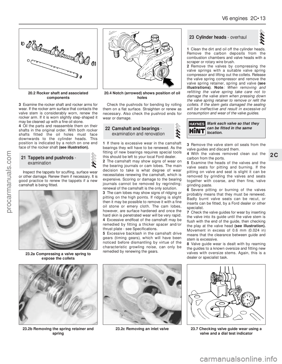
4Oil the parts and reassemble them on their
shafts in the original order. With both rocker
shafts fitted the oil holes must face
downwards to the cylinder heads. This
position is indicated by a notch on one end
face of the rocker shaft (see illustration).
Inspect the tappets for scuffing, surface wear
or other damage. Renew them if necessary. It is
good practice to renew the tappets if a new
camshaft is being fitted.Check the pushrods for bending by rolling
them on a flat surface. Straighten or renew as
necessary. Also check the pushrod ends for
wear or damage.
1If there is excessive wear in the camshaft
bearings they will have to be renewed. As the
fitting of new bearings requires special tools
this should be left to your local Ford dealer.
2The camshaft may show signs of wear on
the bearing journals or cam lobes. The main
decision to take is what degree of wear
necessitates renewing the camshaft, which is
expensive. Scoring or damage to the bearing
journals cannot be removed by regrinding;
renewal of the camshaft is the only solution.
3The cam lobes may show signs of ridging or
pitting on the high points. If ridging is slight
then it may be possible to remove it with a fine
oil stone or emery cloth. The cam lobes,
however, are surface hardened and once the
hard skin is penetrated wear will be very rapid.
4Excessive endfloat of the camshaft may be
remedied by fitting a thicker spacer and/or
thrust plate - see Specifications.
5Excessive backlash in the camshaft drive
gears (timing gears), which will have been
noticed before dismantling by virtue of the
characteristic growling noise, can only be
remedied by renewing the gears.1Clean the dirt and oil off the cylinder heads.
Remove the carbon deposits from the
combustion chambers and valve heads with a
scraper or rotary wire brush.
2Remove the valves by compressing the
valve springs with a suitable valve spring
compressor and lifting out the collets. Release
the valve spring compressor and remove the
valve spring retainer, spring and valve (see
illustrations).Note: When removing and
refitting the valve spring take care not to
damage the valve stem when pressing down
the valve spring retainer to remove or refit the
collets. If the stem gets damaged the sealing
will be ineffective and result in excessive oil
consumption and wear of the valve guides.
3Remove the valve stem oil seals from the
valve guides and discard them.
4With the valves removed clean out the
carbon from the ports.
5Examine the heads of the valves and the
valve seats for pitting and burning. If the
pitting on valve and seat is slight it can be
removed by grinding the valves and seats
together with coarse, and then fine, valve
grinding paste.
6Severe pitting or burning of the valves
probably means that they must be renewed.
Badly burnt valve seats can be recut, or
inserts can be fitted, by a Ford dealer or other
specialist.
7Check the valve guides for wear by inserting
the valve into its guide until the valve stem is
flush with the end of the guide, then checking
the play at the valve head(see illustration).
Movement in excess of 0.6 mm (0.024 in)
means that the clearance between guide and
stem is excessive.
8Valve guide wear is dealt with by reaming
the guides to a known oversize and fitting new
valves with oversize stems. Again, this is a
dealer or specialist task.
23Cylinder heads - overhaul
22Camshaft and bearings -
examination and renovation
21Tappets and pushrods -
examination
V6 engines 2C•13
2C
20.2 Rocker shaft and associated
components20.4 Notch (arrowed) shows position of oil
holes
23.2a Compressing a valve spring to
expose the collets
23.2b Removing the spring retainer and
spring23.2c Removing an inlet valve23.7 Checking valve guide wear using a
valve and a dial test indicator
Mark each valve so that they
can be fitted in the same
location.
procarmanuals.com
Page 75 of 255
9Inspect the valve springs, if possible
comparing their free length with new springs.
Renew the springs anyway if they have been in
use for 20 000 miles (32 000 km) or more.
10Use a straight-edge and feeler blades to
check that the cylinder head mating faces are
not distorted. If they are, have the heads
resurfaced by an engineering works.
11Commence reassembly by oiling a valve
stem and inserting the valve into its guide.
Cover the collet grooves with adhesive tape
and press the new valve stem oil seal down
the stem, using a suitable tube to press the
seals home. Note that the inlet valve seals are
rubber and the exhaust seals nylon. On the 2.8
litre engine, oversize exhaust valve seals must
be used when valves with oversize stems are
fitted. Remove the adhesive tape.
12Fit the valve spring and spring retainer.
Compress the spring and fit the collets, using
a dab of grease to hold them in position.
Carefully release the compressor.
13Tap the valve stem smartly with a mallet to
seat the components.
14Repeat the process on the remaining valves.
Refer to Part A, Section 28 of this Chapter.
The main bearing caps should be fitted, and
their bolts tightened to the specified torque,
when making bore measurements.
Refer to Part A, Section 29 of this Chapter.
1Refer to Part A, Section 27 of this Chapter for
the examination procedure. Note that regrinding
of this crankshaft is not permitted, so if significant
journal wear is present, a new crankshaft (and
new bearing shells) must be fitted.
2As with the SOHC engine, oversize main
bearing parent bores may be encountered.
These are marked with paint stripes on the
bearing caps, corresponding paint marks on
the bearing shells and identification codes on
the backs of the bearing shells.
3On the 2.4 litre engine, separate
thrustwashers are used to control crankshaft
endfloat. On the 2.9 litre engine, No 3 main
bearing shells have integral thrust flanges.
2.8 litre engine
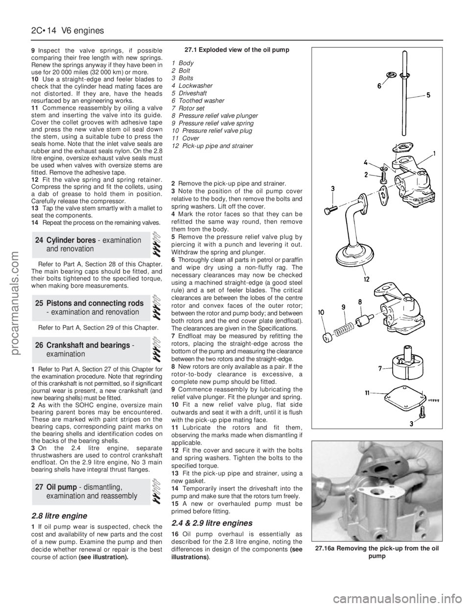
1If oil pump wear is suspected, check the
cost and availability of new parts and the cost
of a new pump. Examine the pump and then
decide whether renewal or repair is the best
course of action (see illustration).2Remove the pick-up pipe and strainer.
3Note the position of the oil pump cover
relative to the body, then remove the bolts and
spring washers. Lift off the cover.
4Mark the rotor faces so that they can be
refitted the same way round, then remove
them from the body.
5Remove the pressure relief valve plug by
piercing it with a punch and levering it out.
Withdraw the spring and plunger.
6Thoroughly clean all parts in petrol or paraffin
and wipe dry using a non-fluffy rag. The
necessary clearances may now be checked
using a machined straight-edge (a good steel
rule) and a set of feeler blades. The critical
clearances are between the lobes of the centre
rotor and convex faces of the outer rotor;
between the rotor and pump body; and between
both rotors and the end cover plate (endfloat).
The clearances are given in the Specifications.
7Endfloat may be measured by refitting the
rotors, placing the straight-edge across the
bottom of the pump and measuring the clearance
between the two rotors and the straight-edge.
8New rotors are only available as a pair. If the
rotor-to-body clearance is excessive, a
complete new pump should be fitted.
9Commence reassembly by lubricating the
relief valve plunger. Fit the plunger and spring.
10Fit a new relief valve plug, flat side
outwards and seat it with a drift, until it is flush
with the pick-up pipe mating face.
11Lubricate the rotors and fit them,
observing the marks made when dismantling if
applicable.
12Fit the cover and secure it with the bolts
and spring washers. Tighten the bolts to the
specified torque.
13Fit the pick-up pipe and strainer, using a
new gasket.
14Temporarily insert the driveshaft into the
pump and make sure that the rotors turn freely.
15A new or overhauled pump must be
primed before fitting.2.4 & 2.9 litre engines
16Oil pump overhaul is essentially as
described for the 2.8 litre engine, noting the
differences in design of the components (see
illustrations).
27Oil pump - dismantling,
examination and reassembly
26Crankshaft and bearings -
examination
25Pistons and connecting rods
- examination and renovation
24Cylinder bores - examination
and renovation
2C•14V6 engines
27.16a Removing the pick-up from the oil
pump
27.1 Exploded view of the oil pump
1 Body
2 Bolt
3 Bolts
4 Lockwasher
5 Driveshaft
6 Toothed washer
7 Rotor set
8 Pressure relief valve plunger
9 Pressure relief valve spring
10 Pressure relief valve plug
11 Cover
12 Pick-up pipe and strainer
procarmanuals.com
Page 76 of 255
Refer to Part A, Section 33 of this Chapter.
The crankcase ventilation system is very
simple. One hose joins the rear air inlet
trunking to the oil filler cap, and another hose
joins the left-hand rocker cover to the plenum
chamber. Filtered (and metered) air passes
through the oil filler cap into the engine, and is
extracted, along with any other fumes, via the
second hose. Refer to Chapter 1 for
maintenance of the system.
Refer to Part A, Section 35 of this Chapter
but disregard the reference to new cylinder
head bolts when these are of the conventional
(hexagon-headed) type. Only Torx type bolts
need to be renewed.
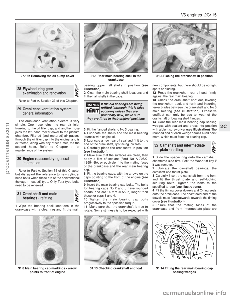
1Wipe the bearing shell locations in the
crankcase with a clean rag and fit the mainbearing upper half shells in position (see
illustration).
2Clean the main bearing shell locations and
fit the half shells in the caps.
3Fit the flanged shells to No 3 bearing.
4Lubricate the shells and the main bearing
journals with engine oil.
5Lubricate a new rear oil seal and fit it to the
end of the crankshaft, lips facing inwards.
6Carefully place the crankshaft in position
(see illustration).
7Make sure that the surfaces are clean, then
apply a film of sealant (Ford No A-70SX-
19554-BA, or equivalent) to the mating faces
of the crankcase and the rear main bearing
cap.
8Fit the bearing caps, with the arrows on the
caps pointing to the front of the engine (see
illustration).
9Insert the main bearing cap bolts. The bolts
for bearing caps No 2 and 3 have rounded
heads, and are 14 mm (0.55 in) longer than
those for caps 1 and 4.
10Tighten the main bearing cap bolts
progressively to the specified torque.
11Make sure that the crankshaft is free to
rotate. Some stiffness is to be expected withnew components, but there should be no tight
spots or binding.
12Press the crankshaft rear oil seal firmly
against the rear main bearing.
13Check the crankshaft endfloat, levering
the crankshaft back and forth and inserting
feeler blades between the crankshaft and No 3
main bearing (see illustration). Excessive
endfloat can only be due to wear of the
crankshaft or bearing shell flanges.
14Coat the rear main bearing cap sealing
wedges with sealant and press into position
with a blunt screwdriver(see illustration).The
rounded end of each wedge carries a red paint
mark, which must face the bearing cap.
1Slide the spacer ring onto the camshaft,
chamfered side first. Refit the Woodruff key if
it was removed.
2Lubricate the camshaft bearings, the
camshaft and thrust plate.
3Carefully insert the camshaft from the front
and fit the thrust plate and self-locking
securing bolts. Tighten the bolts to the
specified torque (see illustrations).
4Fit the timing cover dowels and O-ring seals
onto the crankcase. The chamfered end of the
dowels must face outwards towards the timing
cover (see illustration).
5Ensure that the mating faces of the
crankcase and front intermediate plate are
32Camshaft and intermediate
plate - refitting
31Crankshaft and main
bearings - refitting
30Engine reassembly - general
information
29Crankcase ventilation system -
general information
28Flywheel ring gear -
examination and renovation
V6 engines 2C•15
2C
31.1 Rear main bearing shell in the
crankcase31.6 Placing the crankshaft in position
31.8 Main bearing cap markings - arrow
points to front of engine31.13 Checking crankshaft endfloat31.14 Fitting the rear main bearing cap
sealing wedges
27.16b Removing the oil pump cover
If the old bearings are being
refitted (although this is false
economy unless they are
practically new) make sure
they are fitted in their original positions.
procarmanuals.com
Page 77 of 255
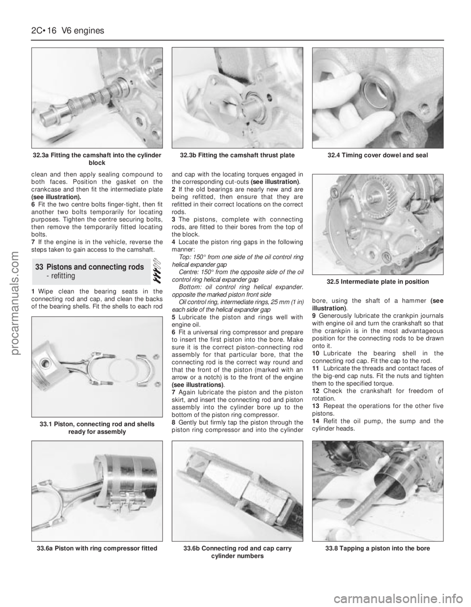
clean and then apply sealing compound to
both faces. Position the gasket on the
crankcase and then fit the intermediate plate
(see illustration).
6Fit the two centre bolts finger-tight, then fit
another two bolts temporarily for locating
purposes. Tighten the centre securing bolts,
then remove the temporarily fitted locating
bolts.
7If the engine is in the vehicle, reverse the
steps taken to gain access to the camshaft.
1Wipe clean the bearing seats in the
connecting rod and cap, and clean the backs
of the bearing shells. Fit the shells to each rodand cap with the locating torques engaged in
the corresponding cut-outs (see illustration).
2If the old bearings are nearly new and are
being refitted, then ensure that they are
refitted in their correct locations on the correct
rods.
3The pistons, complete with connecting
rods, are fitted to their bores from the top of
the block.
4Locate the piston ring gaps in the following
manner:
Top: 150°from one side of the oil control ring
helical expander gap
Centre: 150°from the opposite side of the oil
control ring helical expander gap
Bottom: oil control ring helical expander.
opposite the marked piston front side
Oil control ring, intermediate rings, 25 mm (1 in)
each side of the helical expander gap
5Lubricate the piston and rings well with
engine oil.
6Fit a universal ring compressor and prepare
to insert the first piston into the bore. Make
sure it is the correct piston-connecting rod
assembly for that particular bore, that the
connecting rod is the correct way round and
that the front of the piston (marked with an
arrow or a notch) is to the front of the engine
(see illustrations).
7Again lubricate the piston and the piston
skirt, and insert the connecting rod and piston
assembly into the cylinder bore up to the
bottom of the piston ring compressor.
8Gently but firmly tap the piston through the
piston ring compressor and into the cylinderbore, using the shaft of a hammer (see
illustration).
9Generously lubricate the crankpin journals
with engine oil and turn the crankshaft so that
the crankpin is in the most advantageous
position for the connecting rods to be drawn
onto it.
10Lubricate the bearing shell in the
connecting rod cap. Fit the cap to the rod.
11Lubricate the threads and contact faces of
the big-end cap nuts. Fit the nuts and tighten
them to the specified torque.
12Check the crankshaft for freedom of
rotation.
13Repeat the operations for the other five
pistons.
14Refit the oil pump, the sump and the
cylinder heads.
33Pistons and connecting rods
- refitting
2C•16V6 engines
32.3a Fitting the camshaft into the cylinder
block
33.6a Piston with ring compressor fitted
32.5 Intermediate plate in position
33.6b Connecting rod and cap carry
cylinder numbers33.8 Tapping a piston into the bore
33.1 Piston, connecting rod and shells
ready for assembly
32.3b Fitting the camshaft thrust plate32.4 Timing cover dowel and seal
procarmanuals.com
Page 78 of 255
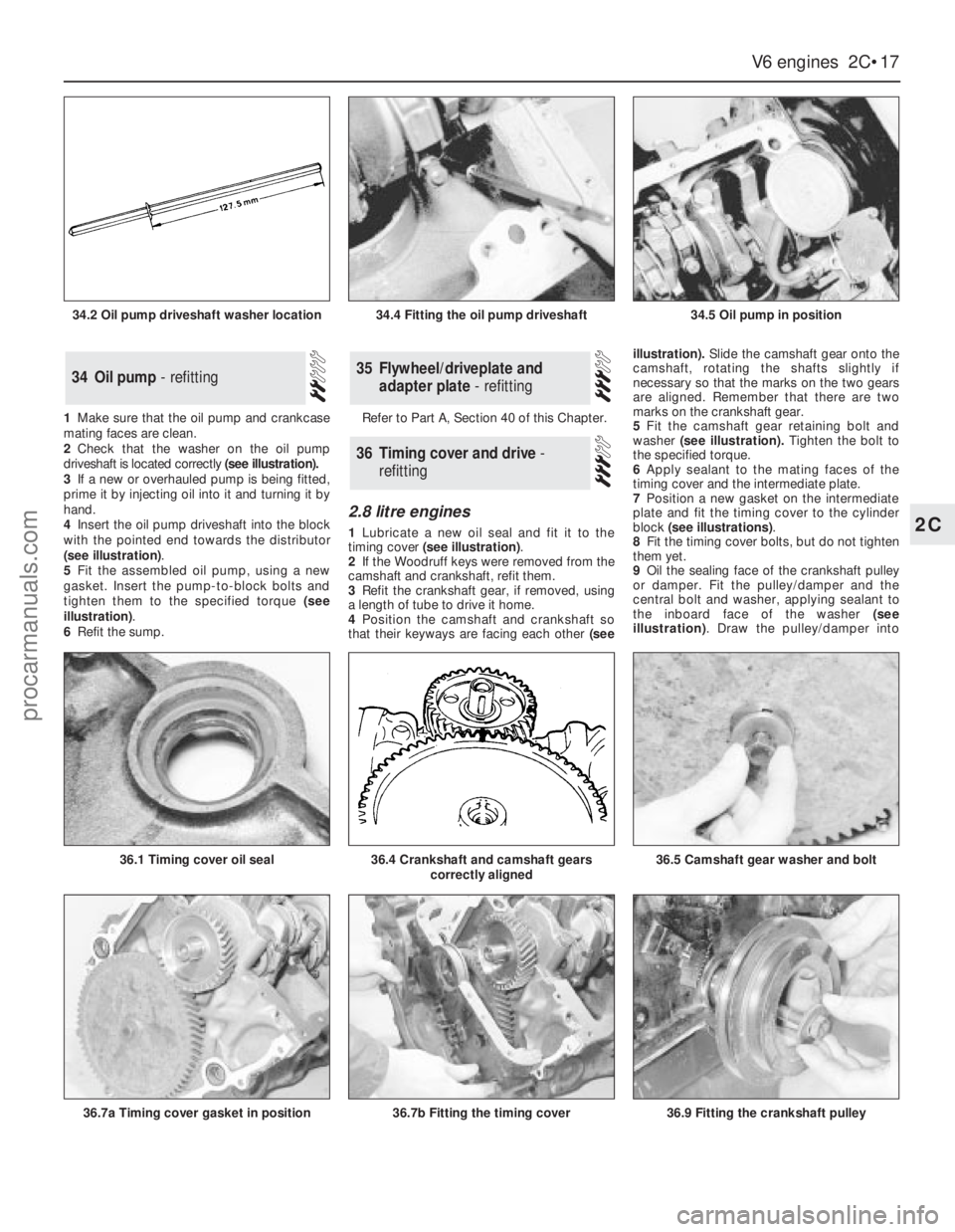
1Make sure that the oil pump and crankcase
mating faces are clean.
2Check that the washer on the oil pump
driveshaft is located correctly (see illustration).
3If a new or overhauled pump is being fitted,
prime it by injecting oil into it and turning it by
hand.
4Insert the oil pump driveshaft into the block
with the pointed end towards the distributor
(see illustration).
5Fit the assembled oil pump, using a new
gasket. Insert the pump-to-block bolts and
tighten them to the specified torque (see
illustration).
6Refit the sump.Refer to Part A, Section 40 of this Chapter.
2.8 litre engines
1Lubricate a new oil seal and fit it to the
timing cover (see illustration).
2If the Woodruff keys were removed from the
camshaft and crankshaft, refit them.
3Refit the crankshaft gear, if removed, using
a length of tube to drive it home.
4Position the camshaft and crankshaft so
that their keyways are facing each other(seeillustration).Slide the camshaft gear onto the
camshaft, rotating the shafts slightly if
necessary so that the marks on the two gears
are aligned. Remember that there are two
marks on the crankshaft gear.
5Fit the camshaft gear retaining bolt and
washer(see illustration).Tighten the bolt to
the specified torque.
6Apply sealant to the mating faces of the
timing cover and the intermediate plate.
7Position a new gasket on the intermediate
plate and fit the timing cover to the cylinder
block (see illustrations).
8Fit the timing cover bolts, but do not tighten
them yet.
9Oil the sealing face of the crankshaft pulley
or damper. Fit the pulley/damper and the
central bolt and washer, applying sealant to
the inboard face of the washer (see
illustration). Draw the pulley/damper into
36Timing cover and drive -
refitting
35Flywheel/driveplate and
adapter plate - refitting34Oil pump - refitting
V6 engines 2C•17
2C
34.2 Oil pump driveshaft washer location34.4 Fitting the oil pump driveshaft34.5 Oil pump in position
36.7a Timing cover gasket in position
36.1 Timing cover oil seal36.5 Camshaft gear washer and bolt36.4 Crankshaft and camshaft gears
correctly aligned
36.7b Fitting the timing cover36.9 Fitting the crankshaft pulley
procarmanuals.com
Page 79 of 255
place by tightening the bolt; this will centralise
the timing cover.
10Tighten the timing cover bolts evenly to
the specified torque.
11Jam the crankshaft and tighten the pulley/
damper central bolt to the specified torque.
12Refit the sump.
13If the water pump was removed from the
timing cover, refit it using a new gasket.
14If the engine is still in the vehicle, reverse
the steps taken to gain access.
2.4 & 2.9 litre engines
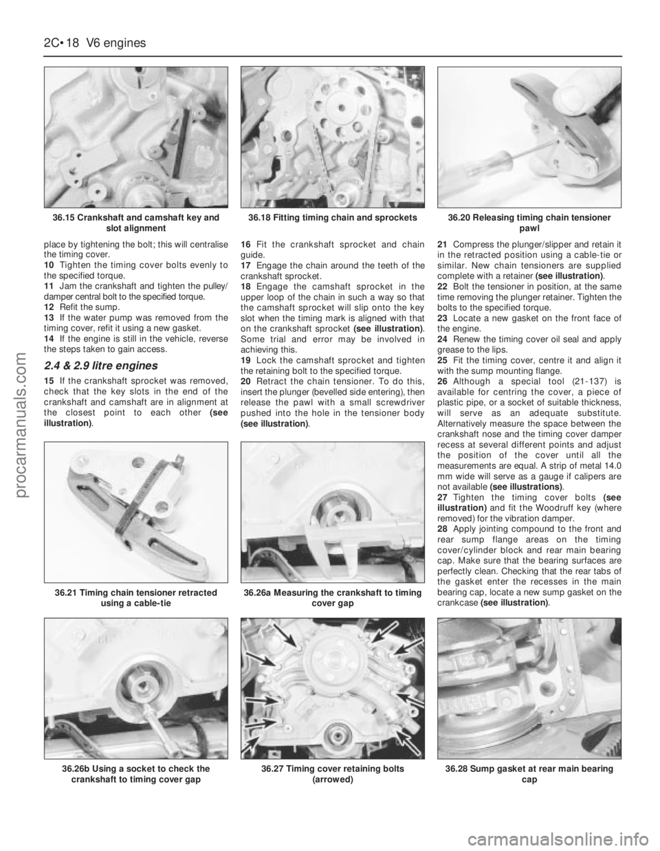
15If the crankshaft sprocket was removed,
check that the key slots in the end of the
crankshaft and camshaft are in alignment at
the closest point to each other (see
illustration).16Fit the crankshaft sprocket and chain
guide.
17Engage the chain around the teeth of the
crankshaft sprocket.
18Engage the camshaft sprocket in the
upper loop of the chain in such a way so that
the camshaft sprocket will slip onto the key
slot when the timing mark is aligned with that
on the crankshaft sprocket (see illustration).
Some trial and error may be involved in
achieving this.
19Lock the camshaft sprocket and tighten
the retaining bolt to the specified torque.
20Retract the chain tensioner. To do this,
insert the plunger (bevelled side entering), then
release the pawl with a small screwdriver
pushed into the hole in the tensioner body
(see illustration).21Compress the plunger/slipper and retain it
in the retracted position using a cable-tie or
similar. New chain tensioners are supplied
complete with a retainer (see illustration).
22Bolt the tensioner in position, at the same
time removing the plunger retainer. Tighten the
bolts to the specified torque.
23Locate a new gasket on the front face of
the engine.
24Renew the timing cover oil seal and apply
grease to the lips.
25Fit the timing cover, centre it and align it
with the sump mounting flange.
26Although a special tool (21-137) is
available for centring the cover, a piece of
plastic pipe, or a socket of suitable thickness,
will serve as an adequate substitute.
Alternatively measure the space between the
crankshaft nose and the timing cover damper
recess at several different points and adjust
the position of the cover until all the
measurements are equal. A strip of metal 14.0
mm wide will serve as a gauge if calipers are
not available (see illustrations).
27Tighten the timing cover bolts (see
illustration)and fit the Woodruff key (where
removed) for the vibration damper.
28Apply jointing compound to the front and
rear sump flange areas on the timing
cover/cylinder block and rear main bearing
cap. Make sure that the bearing surfaces are
perfectly clean. Checking that the rear tabs of
the gasket enter the recesses in the main
bearing cap, locate a new sump gasket on the
crankcase (see illustration).
2C•18V6 engines
36.15 Crankshaft and camshaft key and
slot alignment
36.26b Using a socket to check the
crankshaft to timing cover gap
36.21 Timing chain tensioner retracted
using a cable-tie36.26a Measuring the crankshaft to timing
cover gap
36.27 Timing cover retaining bolts
(arrowed)36.28 Sump gasket at rear main bearing
cap
36.18 Fitting timing chain and sprockets36.20 Releasing timing chain tensioner
pawl
procarmanuals.com
Page 80 of 255
29Fit the sump and the retaining nuts and
bolts. Tighten them progressively in two stages.
30Oil the lip of the timing cover oil seal and
the contact surface of the crankshaft damper.
31Fit the damper to the crankshaft, being
careful not to dislodge the Woodruff key. Draw
the damper into position using the retaining
bolt and washer.
32Remove the bolt and apply sealant to the
faces of the washer. Refit the bolt and washer
then jam the starter gear ring teeth and tighten
the bolt to the specified torque.
33Refit the crankshaft pulley and tighten the
retaining bolts to the specified torque.
34Refit the crossmember side brackets and
brake pipes.
35Reconnect the engine mountings and
remove the engine hoist or axle stands (see
“Jacking”).36Connect the steering shaft coupling with
the steering wheel and front roadwheels in the
straight-ahead position. Fit the pinch-bolt and
tighten it to the specified torque.
37Fit the starter motor and connect the leads.
38Bolt the coolant distributor pipe to the
timing cover.
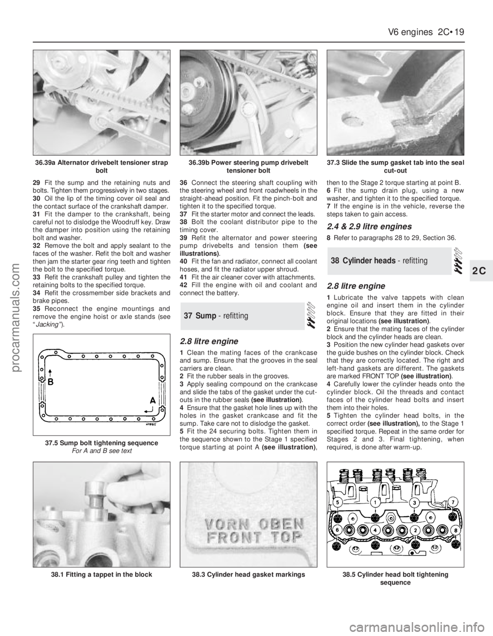
39Refit the alternator and power steering
pump drivebelts and tension them (see
illustrations).
40Fit the fan and radiator, connect all coolant
hoses, and fit the radiator upper shroud.
41Fit the air cleaner cover with attachments.
42Fill the engine with oil and coolant and
connect the battery.
2.8 litre engine
1Clean the mating faces of the crankcase
and sump. Ensure that the grooves in the seal
carriers are clean.
2Fit the rubber seals in the grooves.
3Apply sealing compound on the crankcase
and slide the tabs of the gasket under the cut-
outs in the rubber seals (see illustration).
4Ensure that the gasket hole lines up with the
holes in the gasket crankcase and fit the
sump. Take care not to dislodge the gasket.
5Fit the 24 securing bolts. Tighten them in
the sequence shown to the Stage 1 specified
torque starting at point A (see illustration),then to the Stage 2 torque starting at point B.
6Fit the sump drain plug, using a new
washer, and tighten it to the specified torque.
7If the engine is in the vehicle, reverse the
steps taken to gain access.
2.4 & 2.9 litre engines
8Refer to paragraphs 28 to 29, Section 36.
2.8 litre engine
1Lubricate the valve tappets with clean
engine oil and insert them in the cylinder
block. Ensure that they are fitted in their
original locations (see illustration).
2Ensure that the mating faces of the cylinder
block and the cylinder heads are clean.
3Position the new cylinder head gaskets over
the guide bushes on the cylinder block. Check
that they are correctly located. The right and
left-hand gaskets are different. The gaskets
are marked FRONT TOP (see illustration).
4Carefully lower the cylinder heads onto the
cylinder block. Oil the threads and contact
faces of the cylinder head bolts and insert
them into their holes.
5Tighten the cylinder head bolts, in the
correct order(see illustration),to the Stage 1
specified torque. Repeat in the same order for
Stages 2 and 3. Final tightening, when
required, is done after warm-up.
38Cylinder heads - refitting
37Sump - refitting
V6 engines 2C•19
2C
36.39a Alternator drivebelt tensioner strap
bolt36.39b Power steering pump drivebelt
tensioner bolt37.3 Slide the sump gasket tab into the seal
cut-out
38.1 Fitting a tappet in the block
37.5 Sump bolt tightening sequence
For A and B see text
38.3 Cylinder head gasket markings38.5 Cylinder head bolt tightening
sequence
procarmanuals.com
 1
1 2
2 3
3 4
4 5
5 6
6 7
7 8
8 9
9 10
10 11
11 12
12 13
13 14
14 15
15 16
16 17
17 18
18 19
19 20
20 21
21 22
22 23
23 24
24 25
25 26
26 27
27 28
28 29
29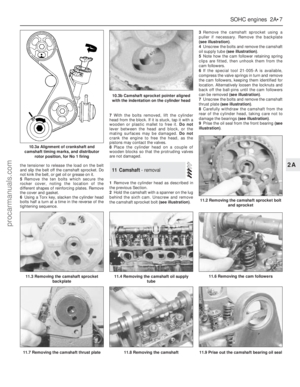 30
30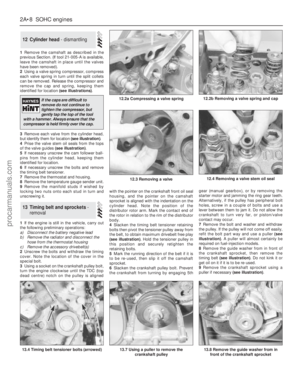 31
31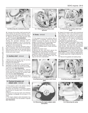 32
32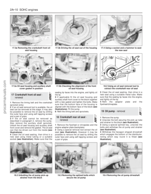 33
33 34
34 35
35 36
36 37
37 38
38 39
39 40
40 41
41 42
42 43
43 44
44 45
45 46
46 47
47 48
48 49
49 50
50 51
51 52
52 53
53 54
54 55
55 56
56 57
57 58
58 59
59 60
60 61
61 62
62 63
63 64
64 65
65 66
66 67
67 68
68 69
69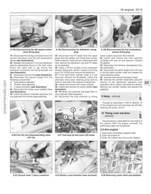 70
70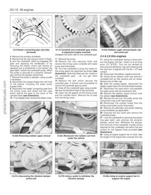 71
71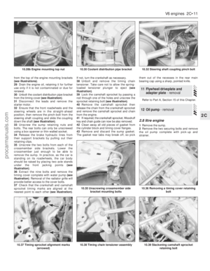 72
72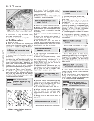 73
73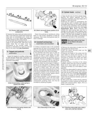 74
74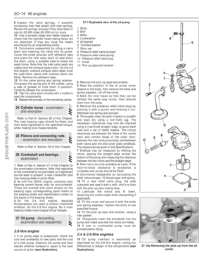 75
75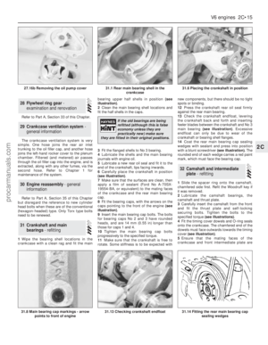 76
76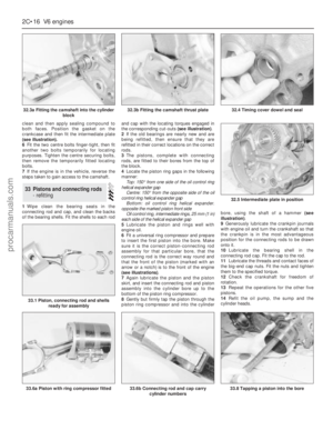 77
77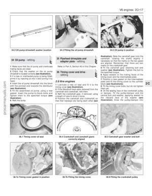 78
78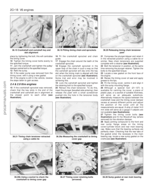 79
79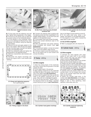 80
80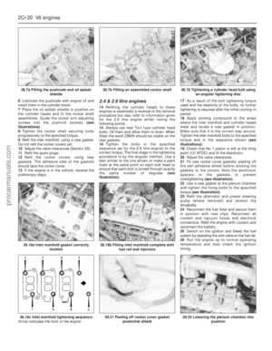 81
81 82
82 83
83 84
84 85
85 86
86 87
87 88
88 89
89 90
90 91
91 92
92 93
93 94
94 95
95 96
96 97
97 98
98 99
99 100
100 101
101 102
102 103
103 104
104 105
105 106
106 107
107 108
108 109
109 110
110 111
111 112
112 113
113 114
114 115
115 116
116 117
117 118
118 119
119 120
120 121
121 122
122 123
123 124
124 125
125 126
126 127
127 128
128 129
129 130
130 131
131 132
132 133
133 134
134 135
135 136
136 137
137 138
138 139
139 140
140 141
141 142
142 143
143 144
144 145
145 146
146 147
147 148
148 149
149 150
150 151
151 152
152 153
153 154
154 155
155 156
156 157
157 158
158 159
159 160
160 161
161 162
162 163
163 164
164 165
165 166
166 167
167 168
168 169
169 170
170 171
171 172
172 173
173 174
174 175
175 176
176 177
177 178
178 179
179 180
180 181
181 182
182 183
183 184
184 185
185 186
186 187
187 188
188 189
189 190
190 191
191 192
192 193
193 194
194 195
195 196
196 197
197 198
198 199
199 200
200 201
201 202
202 203
203 204
204 205
205 206
206 207
207 208
208 209
209 210
210 211
211 212
212 213
213 214
214 215
215 216
216 217
217 218
218 219
219 220
220 221
221 222
222 223
223 224
224 225
225 226
226 227
227 228
228 229
229 230
230 231
231 232
232 233
233 234
234 235
235 236
236 237
237 238
238 239
239 240
240 241
241 242
242 243
243 244
244 245
245 246
246 247
247 248
248 249
249 250
250 251
251 252
252 253
253 254
254


