Page 177 of 255
12•20Notes
procarmanuals.com
Page 178 of 255
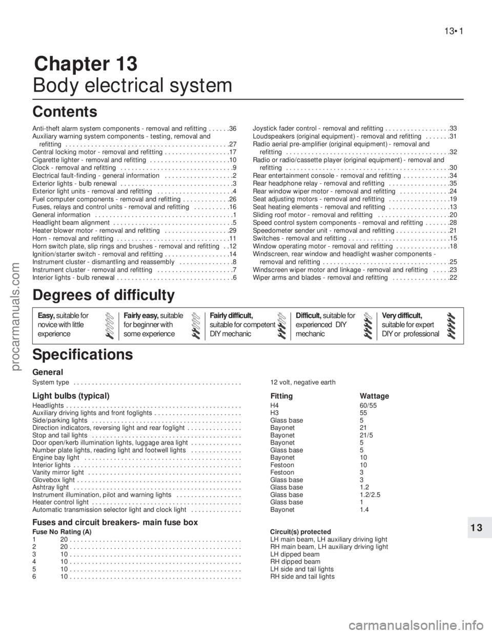
Chapter 13
Body electrical system
Anti-theft alarm system components - removal and refitting . . . . . .36
Auxiliary warning system components - testing, removal and
refitting . . . . . . . . . . . . . . . . . . . . . . . . . . . . . . . . . . . . . . . . . . . . .27
Central locking motor - removal and refitting . . . . . . . . . . . . . . . . . .17
Cigarette lighter - removal and refitting . . . . . . . . . . . . . . . . . . . . . .10
Clock - removal and refitting . . . . . . . . . . . . . . . . . . . . . . . . . . . . . . .9
Electrical fault-finding - general information . . . . . . . . . . . . . . . . . . .2
Exterior lights - bulb renewal . . . . . . . . . . . . . . . . . . . . . . . . . . . . . . .3
Exterior light units - removal and refitting . . . . . . . . . . . . . . . . . . . . .4
Fuel computer components - removal and refitting . . . . . . . . . . . . .26
Fuses, relays and control units - removal and refitting . . . . . . . . . .16
General information . . . . . . . . . . . . . . . . . . . . . . . . . . . . . . . . . . . . . .1
Headlight beam alignment . . . . . . . . . . . . . . . . . . . . . . . . . . . . . . . . .5
Heater blower motor - removal and refitting . . . . . . . . . . . . . . . . . .29
Horn - removal and refitting . . . . . . . . . . . . . . . . . . . . . . . . . . . . . . .11
Horn switch plate, slip rings and brushes - removal and refitting . .12
Ignition/starter switch - removal and refitting . . . . . . . . . . . . . . . . . .14
Instrument cluster - dismantling and reassembly . . . . . . . . . . . . . . .8
Instrument cluster - removal and refitting . . . . . . . . . . . . . . . . . . . . .7
Interior lights - bulb renewal . . . . . . . . . . . . . . . . . . . . . . . . . . . . . . . .6Joystick fader control - removal and refitting . . . . . . . . . . . . . . . . . .33
Loudspeakers (original equipment) - removal and refitting . . . . . . .31
Radio aerial pre-amplifier (original equipment) - removal and
refitting . . . . . . . . . . . . . . . . . . . . . . . . . . . . . . . . . . . . . . . . . . . . .32
Radio or radio/cassette player (original equipment) - removal and
refitting . . . . . . . . . . . . . . . . . . . . . . . . . . . . . . . . . . . . . . . . . . . . .30
Rear entertainment console - removal and refitting . . . . . . . . . . . . .34
Rear headphone relay - removal and refitting . . . . . . . . . . . . . . . . .35
Rear window wiper motor - removal and refitting . . . . . . . . . . . . . .24
Seat adjusting motors - removal and refitting . . . . . . . . . . . . . . . . .19
Seat heating elements - removal and refitting . . . . . . . . . . . . . . . . .13
Sliding roof motor - removal and refitting . . . . . . . . . . . . . . . . . . . .20
Speed control system components - removal and refitting . . . . . . .28
Speedometer sender unit - removal and refitting . . . . . . . . . . . . . . .21
Switches - removal and refitting . . . . . . . . . . . . . . . . . . . . . . . . . . . .15
Window operating motor - removal and refitting . . . . . . . . . . . . . . .18
Windscreen, rear window and headlight washer components -
removal and refitting . . . . . . . . . . . . . . . . . . . . . . . . . . . . . . . . . . .25
Windscreen wiper motor and linkage - removal and refitting . . . . .23
Wiper arms and blades - removal and refitting . . . . . . . . . . . . . . . .22
General
System type . . . . . . . . . . . . . . . . . . . . . . . . . . . . . . . . . . . . . . . . . . . . . . 12 volt, negative earth
Light bulbs (typical)Fitting Wattage
Headlights . . . . . . . . . . . . . . . . . . . . . . . . . . . . . . . . . . . . . . . . . . . . . . . . H4 60/55
Auxiliary driving lights and front foglights . . . . . . . . . . . . . . . . . . . . . . . . H3 55
Side/parking lights . . . . . . . . . . . . . . . . . . . . . . . . . . . . . . . . . . . . . . . . . Glass base 5
Direction indicators, reversing light and rear foglight . . . . . . . . . . . . . . . Bayonet 21
Stop and tail lights . . . . . . . . . . . . . . . . . . . . . . . . . . . . . . . . . . . . . . . . . Bayonet 21/5
Door open/kerb illumination lights, luggage area light . . . . . . . . . . . . . . Bayonet 5
Number plate lights, reading light and footwell lights . . . . . . . . . . . . . . Glass base 5
Engine bay light . . . . . . . . . . . . . . . . . . . . . . . . . . . . . . . . . . . . . . . . . . . Bayonet 10
Interior lights . . . . . . . . . . . . . . . . . . . . . . . . . . . . . . . . . . . . . . . . . . . . . . Festoon 10
Vanity mirror light . . . . . . . . . . . . . . . . . . . . . . . . . . . . . . . . . . . . . . . . . . Festoon 3
Glovebox light . . . . . . . . . . . . . . . . . . . . . . . . . . . . . . . . . . . . . . . . . . . . . Glass base 3
Ashtray light . . . . . . . . . . . . . . . . . . . . . . . . . . . . . . . . . . . . . . . . . . . . . . Glass base 1.2
Instrument illumination, pilot and warning lights . . . . . . . . . . . . . . . . . . Glass base 1.2/2.5
Heater control light . . . . . . . . . . . . . . . . . . . . . . . . . . . . . . . . . . . . . . . . . Glass base 1
Automatic transmission selector light and clock light . . . . . . . . . . . . . . Bayonet 1.4
Fuses and circuit breakers- main fuse box
Fuse No Rating (A) Circuit(s) protected
1 20 . . . . . . . . . . . . . . . . . . . . . . . . . . . . . . . . . . . . . . . . . . . . . . . LH main beam, LH auxiliary driving light
2 20 . . . . . . . . . . . . . . . . . . . . . . . . . . . . . . . . . . . . . . . . . . . . . . . RH main beam, LH auxiliary driving light
3 10 . . . . . . . . . . . . . . . . . . . . . . . . . . . . . . . . . . . . . . . . . . . . . . . LH dipped beam
4 10 . . . . . . . . . . . . . . . . . . . . . . . . . . . . . . . . . . . . . . . . . . . . . . . RH dipped beam
5 10 . . . . . . . . . . . . . . . . . . . . . . . . . . . . . . . . . . . . . . . . . . . . . . . LH side and tail lights
6 10 . . . . . . . . . . . . . . . . . . . . . . . . . . . . . . . . . . . . . . . . . . . . . . . RH side and tail lights
13•1
Easy,suitable for
novice with little
experienceFairly easy,suitable
for beginner with
some experienceFairly difficult,
suitable for competent
DIY mechanicDifficult,suitable for
experienced DIY
mechanicVery difficult,
suitable for expert
DIY or professional
Degrees of difficulty
Specifications Contents
13
procarmanuals.com
Page 179 of 255
13•2Body electrical system
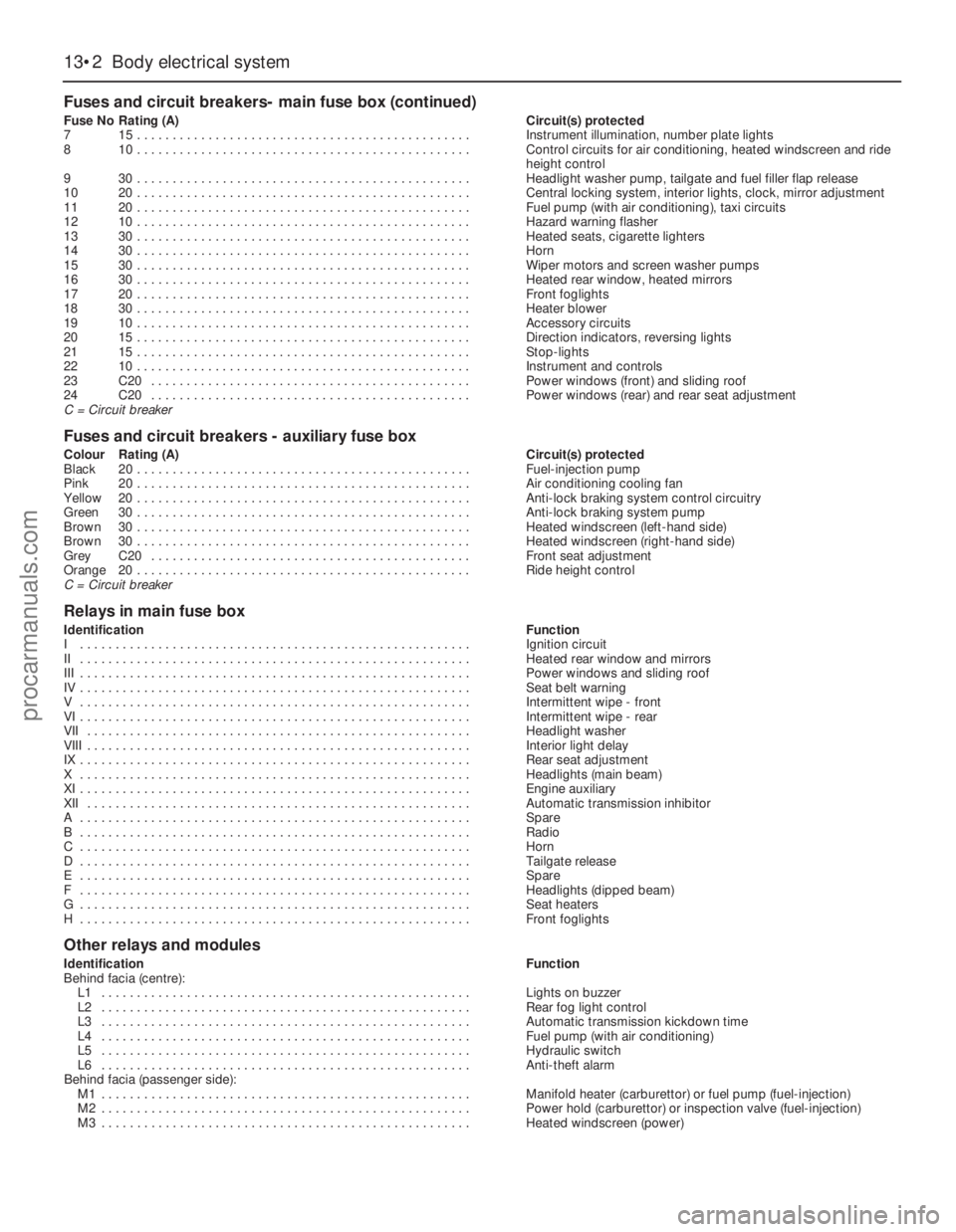
Fuses and circuit breakers- main fuse box (continued)
Fuse NoRating (A)Circuit(s) protected
715 . . . . . . . . . . . . . . . . . . . . . . . . . . . . . . . . . . . . . . . . . . . . . . .Instrument illumination, number plate lights
810 . . . . . . . . . . . . . . . . . . . . . . . . . . . . . . . . . . . . . . . . . . . . . . .Control circuits for air conditioning, heated windscreen and ride
height control
930 . . . . . . . . . . . . . . . . . . . . . . . . . . . . . . . . . . . . . . . . . . . . . . .Headlight washer pump, tailgate and fuel filler flap release
1020 . . . . . . . . . . . . . . . . . . . . . . . . . . . . . . . . . . . . . . . . . . . . . . .Central locking system, interior lights, clock, mirror adjustment
1120 . . . . . . . . . . . . . . . . . . . . . . . . . . . . . . . . . . . . . . . . . . . . . . .Fuel pump (with air conditioning), taxi circuits
1210 . . . . . . . . . . . . . . . . . . . . . . . . . . . . . . . . . . . . . . . . . . . . . . .Hazard warning flasher
1330 . . . . . . . . . . . . . . . . . . . . . . . . . . . . . . . . . . . . . . . . . . . . . . .Heated seats, cigarette lighters
1430 . . . . . . . . . . . . . . . . . . . . . . . . . . . . . . . . . . . . . . . . . . . . . . .Horn
1530 . . . . . . . . . . . . . . . . . . . . . . . . . . . . . . . . . . . . . . . . . . . . . . .Wiper motors and screen washer pumps
1630 . . . . . . . . . . . . . . . . . . . . . . . . . . . . . . . . . . . . . . . . . . . . . . .Heated rear window, heated mirrors
1720 . . . . . . . . . . . . . . . . . . . . . . . . . . . . . . . . . . . . . . . . . . . . . . .Front foglights
1830 . . . . . . . . . . . . . . . . . . . . . . . . . . . . . . . . . . . . . . . . . . . . . . .Heater blower
1910 . . . . . . . . . . . . . . . . . . . . . . . . . . . . . . . . . . . . . . . . . . . . . . .Accessory circuits
2015 . . . . . . . . . . . . . . . . . . . . . . . . . . . . . . . . . . . . . . . . . . . . . . .Direction indicators, reversing lights
2115 . . . . . . . . . . . . . . . . . . . . . . . . . . . . . . . . . . . . . . . . . . . . . . .Stop-lights
2210 . . . . . . . . . . . . . . . . . . . . . . . . . . . . . . . . . . . . . . . . . . . . . . .Instrument and controls
23C20 . . . . . . . . . . . . . . . . . . . . . . . . . . . . . . . . . . . . . . . . . . . . .Power windows (front) and sliding roof
24C20 . . . . . . . . . . . . . . . . . . . . . . . . . . . . . . . . . . . . . . . . . . . . .Power windows (rear) and rear seat adjustment
C = Circuit breaker
Fuses and circuit breakers - auxiliary fuse box
Colour Rating (A)Circuit(s) protected
Black20 . . . . . . . . . . . . . . . . . . . . . . . . . . . . . . . . . . . . . . . . . . . . . . .Fuel-injection pump
Pink20 . . . . . . . . . . . . . . . . . . . . . . . . . . . . . . . . . . . . . . . . . . . . . . .Air conditioning cooling fan
Yellow20 . . . . . . . . . . . . . . . . . . . . . . . . . . . . . . . . . . . . . . . . . . . . . . .Anti-lock braking system control circuitry
Green30 . . . . . . . . . . . . . . . . . . . . . . . . . . . . . . . . . . . . . . . . . . . . . . .Anti-lock braking system pump
Brown30 . . . . . . . . . . . . . . . . . . . . . . . . . . . . . . . . . . . . . . . . . . . . . . .Heated windscreen (left-hand side)
Brown30 . . . . . . . . . . . . . . . . . . . . . . . . . . . . . . . . . . . . . . . . . . . . . . .Heated windscreen (right-hand side)
GreyC20 . . . . . . . . . . . . . . . . . . . . . . . . . . . . . . . . . . . . . . . . . . . . .Front seat adjustment
Orange20 . . . . . . . . . . . . . . . . . . . . . . . . . . . . . . . . . . . . . . . . . . . . . . .Ride height control
C = Circuit breaker
Relays in main fuse box
IdentificationFunction
I . . . . . . . . . . . . . . . . . . . . . . . . . . . . . . . . . . . . . . . . . . . . . . . . . . . . . . .Ignition circuit
II . . . . . . . . . . . . . . . . . . . . . . . . . . . . . . . . . . . . . . . . . . . . . . . . . . . . . . .Heated rear window and mirrors
III . . . . . . . . . . . . . . . . . . . . . . . . . . . . . . . . . . . . . . . . . . . . . . . . . . . . . . .Power windows and sliding roof
IV . . . . . . . . . . . . . . . . . . . . . . . . . . . . . . . . . . . . . . . . . . . . . . . . . . . . . . .Seat belt warning
V . . . . . . . . . . . . . . . . . . . . . . . . . . . . . . . . . . . . . . . . . . . . . . . . . . . . . . .Intermittent wipe - front
VI . . . . . . . . . . . . . . . . . . . . . . . . . . . . . . . . . . . . . . . . . . . . . . . . . . . . . . .Intermittent wipe - rear
VII . . . . . . . . . . . . . . . . . . . . . . . . . . . . . . . . . . . . . . . . . . . . . . . . . . . . . .Headlight washer
VIII . . . . . . . . . . . . . . . . . . . . . . . . . . . . . . . . . . . . . . . . . . . . . . . . . . . . . .Interior light delay
IX . . . . . . . . . . . . . . . . . . . . . . . . . . . . . . . . . . . . . . . . . . . . . . . . . . . . . . .Rear seat adjustment
X . . . . . . . . . . . . . . . . . . . . . . . . . . . . . . . . . . . . . . . . . . . . . . . . . . . . . . .Headlights (main beam)
XI . . . . . . . . . . . . . . . . . . . . . . . . . . . . . . . . . . . . . . . . . . . . . . . . . . . . . . .Engine auxiliary
XII . . . . . . . . . . . . . . . . . . . . . . . . . . . . . . . . . . . . . . . . . . . . . . . . . . . . . .Automatic transmission inhibitor
A . . . . . . . . . . . . . . . . . . . . . . . . . . . . . . . . . . . . . . . . . . . . . . . . . . . . . . .Spare
B . . . . . . . . . . . . . . . . . . . . . . . . . . . . . . . . . . . . . . . . . . . . . . . . . . . . . . .Radio
C . . . . . . . . . . . . . . . . . . . . . . . . . . . . . . . . . . . . . . . . . . . . . . . . . . . . . . .Horn
D . . . . . . . . . . . . . . . . . . . . . . . . . . . . . . . . . . . . . . . . . . . . . . . . . . . . . . .Tailgate release
E . . . . . . . . . . . . . . . . . . . . . . . . . . . . . . . . . . . . . . . . . . . . . . . . . . . . . . .Spare
F . . . . . . . . . . . . . . . . . . . . . . . . . . . . . . . . . . . . . . . . . . . . . . . . . . . . . . .Headlights (dipped beam)
G . . . . . . . . . . . . . . . . . . . . . . . . . . . . . . . . . . . . . . . . . . . . . . . . . . . . . . .Seat heaters
H . . . . . . . . . . . . . . . . . . . . . . . . . . . . . . . . . . . . . . . . . . . . . . . . . . . . . . .Front foglights
Other relays and modules
IdentificationFunction
Behind facia (centre):
L1 . . . . . . . . . . . . . . . . . . . . . . . . . . . . . . . . . . . . . . . . . . . . . . . . . . . .Lights on buzzer
L2 . . . . . . . . . . . . . . . . . . . . . . . . . . . . . . . . . . . . . . . . . . . . . . . . . . . .Rear fog light control
L3 . . . . . . . . . . . . . . . . . . . . . . . . . . . . . . . . . . . . . . . . . . . . . . . . . . . .Automatic transmission kickdown time
L4 . . . . . . . . . . . . . . . . . . . . . . . . . . . . . . . . . . . . . . . . . . . . . . . . . . . .Fuel pump (with air conditioning)
L5 . . . . . . . . . . . . . . . . . . . . . . . . . . . . . . . . . . . . . . . . . . . . . . . . . . . .Hydraulic switch
L6 . . . . . . . . . . . . . . . . . . . . . . . . . . . . . . . . . . . . . . . . . . . . . . . . . . . .Anti-theft alarm
Behind facia (passenger side):
M1 . . . . . . . . . . . . . . . . . . . . . . . . . . . . . . . . . . . . . . . . . . . . . . . . . . . .Manifold heater (carburettor) or fuel pump (fuel-injection)
M2 . . . . . . . . . . . . . . . . . . . . . . . . . . . . . . . . . . . . . . . . . . . . . . . . . . . .Power hold (carburettor) or inspection valve (fuel-injection)
M3 . . . . . . . . . . . . . . . . . . . . . . . . . . . . . . . . . . . . . . . . . . . . . . . . . . . .Heated windscreen (power)
procarmanuals.com
Page 180 of 255
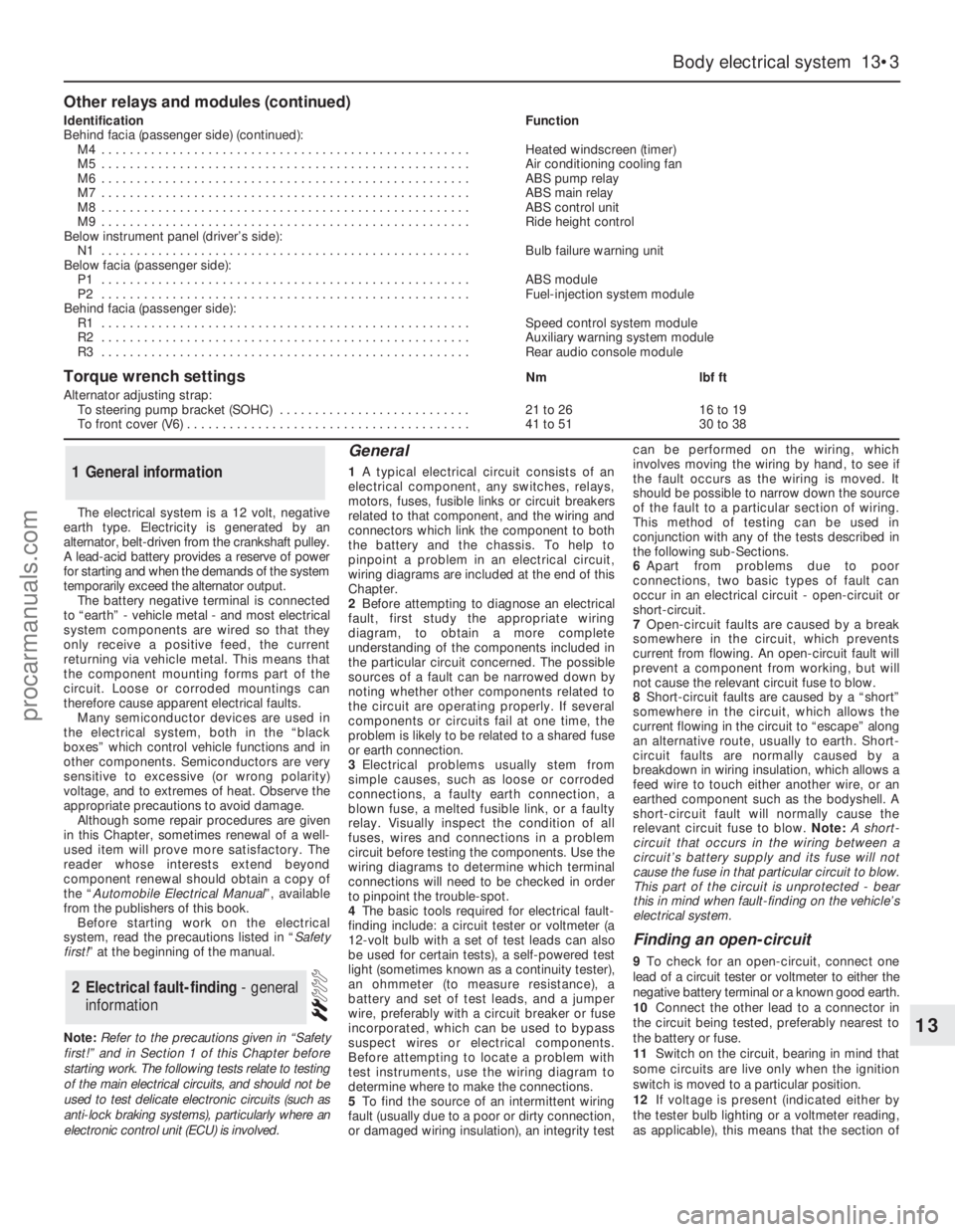
The electrical system is a 12 volt, negative
earth type. Electricity is generated by an
alternator, belt-driven from the crankshaft pulley.
A lead-acid battery provides a reserve of power
for starting and when the demands of the system
temporarily exceed the alternator output.
The battery negative terminal is connected
to “earth” - vehicle metal - and most electrical
system components are wired so that they
only receive a positive feed, the current
returning via vehicle metal. This means that
the component mounting forms part of the
circuit. Loose or corroded mountings can
therefore cause apparent electrical faults.
Many semiconductor devices are used in
the electrical system, both in the “black
boxes” which control vehicle functions and in
other components. Semiconductors are very
sensitive to excessive (or wrong polarity)
voltage, and to extremes of heat. Observe the
appropriate precautions to avoid damage.
Although some repair procedures are given
in this Chapter, sometimes renewal of a well-
used item will prove more satisfactory. The
reader whose interests extend beyond
component renewal should obtain a copy of
the “Automobile Electrical Manual”, available
from the publishers of this book.
Before starting work on the electrical
system, read the precautions listed in “Safety
first!” at the beginning of the manual.
Note:Refer to the precautions given in “Safety
first!” and in Section 1 of this Chapter before
starting work. The following tests relate to testing
of the main electrical circuits, and should not be
used to test delicate electronic circuits (such as
anti-lock braking systems), particularly where an
electronic control unit (ECU) is involved.
General
1A typical electrical circuit consists of an
electrical component, any switches, relays,
motors, fuses, fusible links or circuit breakers
related to that component, and the wiring and
connectors which link the component to both
the battery and the chassis. To help to
pinpoint a problem in an electrical circuit,
wiring diagrams are included at the end of this
Chapter.
2Before attempting to diagnose an electrical
fault, first study the appropriate wiring
diagram, to obtain a more complete
understanding of the components included in
the particular circuit concerned. The possible
sources of a fault can be narrowed down by
noting whether other components related to
the circuit are operating properly. If several
components or circuits fail at one time, the
problem is likely to be related to a shared fuse
or earth connection.
3Electrical problems usually stem from
simple causes, such as loose or corroded
connections, a faulty earth connection, a
blown fuse, a melted fusible link, or a faulty
relay. Visually inspect the condition of all
fuses, wires and connections in a problem
circuit before testing the components. Use the
wiring diagrams to determine which terminal
connections will need to be checked in order
to pinpoint the trouble-spot.
4The basic tools required for electrical fault-
finding include: a circuit tester or voltmeter (a
12-volt bulb with a set of test leads can also
be used for certain tests), a self-powered test
light (sometimes known as a continuity tester),
an ohmmeter (to measure resistance), a
battery and set of test leads, and a jumper
wire, preferably with a circuit breaker or fuse
incorporated, which can be used to bypass
suspect wires or electrical components.
Before attempting to locate a problem with
test instruments, use the wiring diagram to
determine where to make the connections.
5To find the source of an intermittent wiring
fault (usually due to a poor or dirty connection,
or damaged wiring insulation), an integrity testcan be performed on the wiring, which
involves moving the wiring by hand, to see if
the fault occurs as the wiring is moved. It
should be possible to narrow down the source
of the fault to a particular section of wiring.
This method of testing can be used in
conjunction with any of the tests described in
the following sub-Sections.
6Apart from problems due to poor
connections, two basic types of fault can
occur in an electrical circuit - open-circuit or
short-circuit.
7Open-circuit faults are caused by a break
somewhere in the circuit, which prevents
current from flowing. An open-circuit fault will
prevent a component from working, but will
not cause the relevant circuit fuse to blow.
8Short-circuit faults are caused by a “short”
somewhere in the circuit, which allows the
current flowing in the circuit to “escape” along
an alternative route, usually to earth. Short-
circuit faults are normally caused by a
breakdown in wiring insulation, which allows a
feed wire to touch either another wire, or an
earthed component such as the bodyshell. A
short-circuit fault will normally cause the
relevant circuit fuse to blow. Note: A short-
circuit that occurs in the wiring between a
circuit’s battery supply and its fuse will not
cause the fuse in that particular circuit to blow.
This part of the circuit is unprotected - bear
this in mind when fault-finding on the vehicle’s
electrical system.
Finding an open-circuit
9To check for an open-circuit, connect one
lead of a circuit tester or voltmeter to either the
negative battery terminal or a known good earth.
10Connect the other lead to a connector in
the circuit being tested, preferably nearest to
the battery or fuse.
11Switch on the circuit, bearing in mind that
some circuits are live only when the ignition
switch is moved to a particular position.
12If voltage is present (indicated either by
the tester bulb lighting or a voltmeter reading,
as applicable), this means that the section of
2Electrical fault-finding - general
information
1General information
Body electrical system 13•3
13
Other relays and modules (continued)
IdentificationFunction
Behind facia (passenger side) (continued):
M4 . . . . . . . . . . . . . . . . . . . . . . . . . . . . . . . . . . . . . . . . . . . . . . . . . . . .Heated windscreen (timer)
M5 . . . . . . . . . . . . . . . . . . . . . . . . . . . . . . . . . . . . . . . . . . . . . . . . . . . .Air conditioning cooling fan
M6 . . . . . . . . . . . . . . . . . . . . . . . . . . . . . . . . . . . . . . . . . . . . . . . . . . . .ABS pump relay
M7 . . . . . . . . . . . . . . . . . . . . . . . . . . . . . . . . . . . . . . . . . . . . . . . . . . . .ABS main relay
M8 . . . . . . . . . . . . . . . . . . . . . . . . . . . . . . . . . . . . . . . . . . . . . . . . . . . .ABS control unit
M9 . . . . . . . . . . . . . . . . . . . . . . . . . . . . . . . . . . . . . . . . . . . . . . . . . . . .Ride height control
Below instrument panel (driver’s side):
N1 . . . . . . . . . . . . . . . . . . . . . . . . . . . . . . . . . . . . . . . . . . . . . . . . . . . .Bulb failure warning unit
Below facia (passenger side):
P1 . . . . . . . . . . . . . . . . . . . . . . . . . . . . . . . . . . . . . . . . . . . . . . . . . . . .ABS module
P2 . . . . . . . . . . . . . . . . . . . . . . . . . . . . . . . . . . . . . . . . . . . . . . . . . . . .Fuel-injection system module
Behind facia (passenger side):
R1 . . . . . . . . . . . . . . . . . . . . . . . . . . . . . . . . . . . . . . . . . . . . . . . . . . . .Speed control system module
R2 . . . . . . . . . . . . . . . . . . . . . . . . . . . . . . . . . . . . . . . . . . . . . . . . . . . .Auxiliary warning system module
R3 . . . . . . . . . . . . . . . . . . . . . . . . . . . . . . . . . . . . . . . . . . . . . . . . . . . .Rear audio console module
Torque wrench settingsNmlbf ft
Alternator adjusting strap:
To steering pump bracket (SOHC) . . . . . . . . . . . . . . . . . . . . . . . . . . .21 to 2616 to 19
To front cover (V6) . . . . . . . . . . . . . . . . . . . . . . . . . . . . . . . . . . . . . . . .41 to 5130 to 38
procarmanuals.com
Page 181 of 255
the circuit between the relevant connector and
the battery is problem-free.
13Continue to check the remainder of the
circuit in the same fashion.
14When a point is reached at which no
voltage is present, the problem must lie
between that point and the previous test point
with voltage. Most problems can be traced to
a broken, corroded or loose connection.
Finding a short-circuit
15To check for a short-circuit, first disconnect
the load(s) from the circuit (loads are the
components which draw current from a circuit,
such as bulbs, motors, heating elements, etc).
16Remove the relevant fuse from the circuit,
and connect a circuit tester or voltmeter to the
fuse connections.
17Switch on the circuit, bearing in mind that
some circuits are live only when the ignition
switch is moved to a particular position.
18If voltage is present (indicated either by
the tester bulb lighting or a voltmeter reading),
this means that there is a short-circuit.
19If no voltage is present, but the fuse still
blows with the load(s) connected, this
indicates an internal fault in the load(s).
Finding an earth fault
20The battery negative terminal is connected
to “earth” - the metal of the engine/transmission
and the car body - and most systems are wired
so that they only receive a positive feed, the
current returning via the metal of the car body.
This means that the component mounting andthe body form part of that circuit. Loose or
corroded mountings can therefore cause a range
of electrical faults, ranging from total failure of a
circuit, to a puzzling partial fault. In particular,
lights may shine dimly (especially when another
circuit sharing the same earth is in operation),
motors (eg wiper motors or the radiator cooling
fan motor) may run slowly, and the operation of
one circuit may have an apparently-unrelated
effect on another. Note that on many vehicles,
earth straps are used between certain
components, such as the engine/transmission
and the body, usually where there is no metal-to-
metal contact between components, due to
flexible rubber mountings, etc.
21To check whether a component is properly
earthed, disconnect the battery, and connect
one lead of an ohmmeter to a known good
earth point. Connect the other lead to the wire
or earth connection being tested. The
resistance reading should be zero; if not,
check the connection as follows.
22If an earth connection is thought to be
faulty, dismantle the connection, and clean
back to bare metal both the bodyshell and the
wire terminal, or the component’s earth
connection mating surface. Be careful to
remove all traces of dirt and corrosion, then
use a knife to trim away any paint, so that a
clean metal-to-metal joint is made. On
reassembly, tighten the joint fasteners
securely; if a wire terminal is being refitted, use
serrated washers between the terminal and
the bodyshell, to ensure a clean and secure
connection. When the connection is remade,
prevent the onset of corrosion in the future byapplying a coat of petroleum jelly or silicone-
based grease, or by spraying on (at regular
intervals) a proprietary ignition sealer, or a
water-dispersant lubricant.
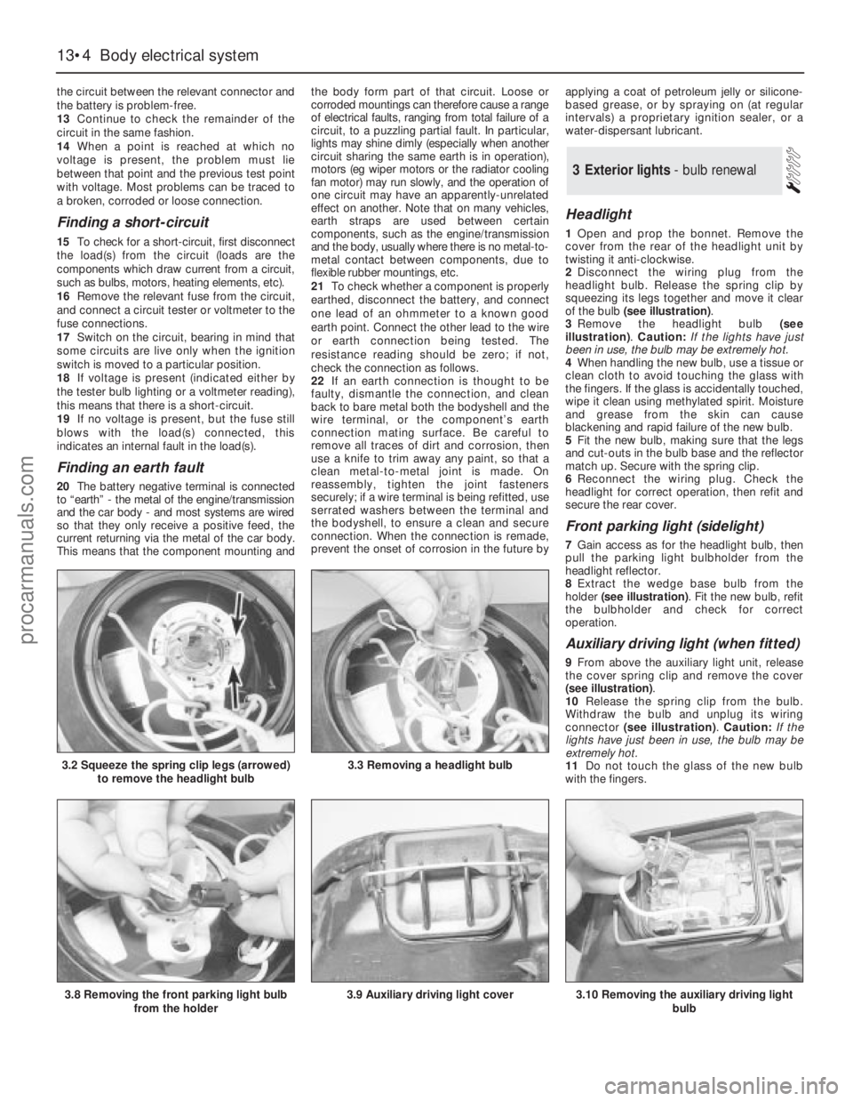
Headlight
1Open and prop the bonnet. Remove the
cover from the rear of the headlight unit by
twisting it anti-clockwise.
2Disconnect the wiring plug from the
headlight bulb. Release the spring clip by
squeezing its legs together and move it clear
of the bulb (see illustration).
3Remove the headlight bulb (see
illustration). Caution: If the lights have just
been in use, the bulb may be extremely hot.
4When handling the new bulb, use a tissue or
clean cloth to avoid touching the glass with
the fingers. If the glass is accidentally touched,
wipe it clean using methylated spirit. Moisture
and grease from the skin can cause
blackening and rapid failure of the new bulb.
5Fit the new bulb, making sure that the legs
and cut-outs in the bulb base and the reflector
match up. Secure with the spring clip.
6Reconnect the wiring plug. Check the
headlight for correct operation, then refit and
secure the rear cover.
Front parking light (sidelight)
7Gain access as for the headlight bulb, then
pull the parking light bulbholder from the
headlight reflector.
8Extract the wedge base bulb from the
holder (see illustration). Fit the new bulb, refit
the bulbholder and check for correct
operation.
Auxiliary driving light (when fitted)
9From above the auxiliary light unit, release
the cover spring clip and remove the cover
(see illustration).
10Release the spring clip from the bulb.
Withdraw the bulb and unplug its wiring
connector (see illustration). Caution: If the
lights have just been in use, the bulb may be
extremely hot.
11Do not touch the glass of the new bulb
with the fingers.
3Exterior lights - bulb renewal
13•4Body electrical system
3.2 Squeeze the spring clip legs (arrowed)
to remove the headlight bulb3.3 Removing a headlight bulb
3.8 Removing the front parking light bulb
from the holder3.9 Auxiliary driving light cover3.10 Removing the auxiliary driving light
bulb
procarmanuals.com
Page 182 of 255
12Connect the new bulb, fit it and secure it
with the spring clip.
13Check the light for correct operation, then
refit and secure the cover.
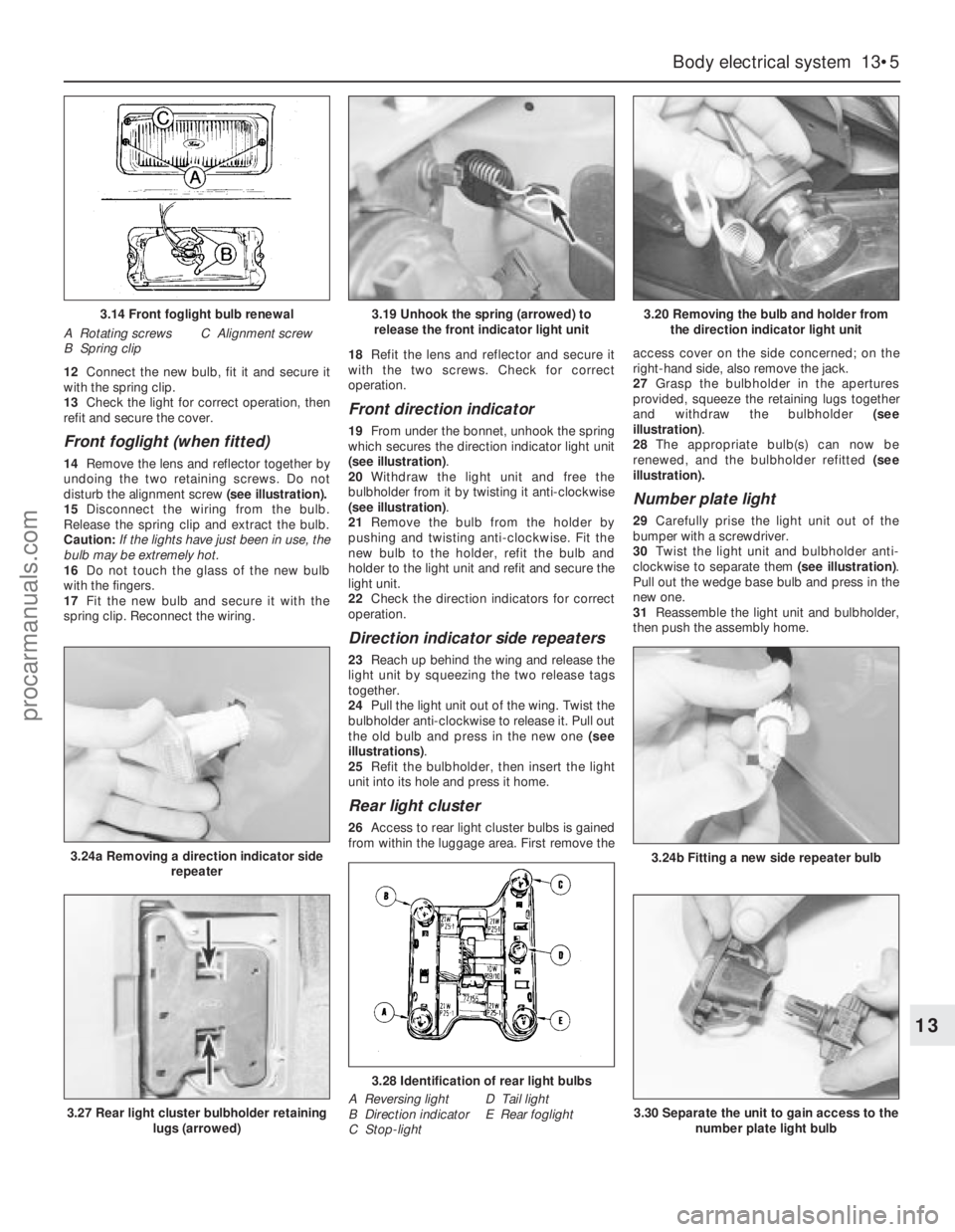
Front foglight (when fitted)
14Remove the lens and reflector together by
undoing the two retaining screws. Do not
disturb the alignment screw (see illustration).
15Disconnect the wiring from the bulb.
Release the spring clip and extract the bulb.
Caution: If the lights have just been in use, the
bulb may be extremely hot.
16Do not touch the glass of the new bulb
with the fingers.
17Fit the new bulb and secure it with the
spring clip. Reconnect the wiring.18Refit the lens and reflector and secure it
with the two screws. Check for correct
operation.
Front direction indicator
19From under the bonnet, unhook the spring
which secures the direction indicator light unit
(see illustration).
20Withdraw the light unit and free the
bulbholder from it by twisting it anti-clockwise
(see illustration).
21Remove the bulb from the holder by
pushing and twisting anti-clockwise. Fit the
new bulb to the holder, refit the bulb and
holder to the light unit and refit and secure the
light unit.
22Check the direction indicators for correct
operation.
Direction indicator side repeaters
23Reach up behind the wing and release the
light unit by squeezing the two release tags
together.
24Pull the light unit out of the wing. Twist the
bulbholder anti-clockwise to release it. Pull out
the old bulb and press in the new one (see
illustrations).
25Refit the bulbholder, then insert the light
unit into its hole and press it home.
Rear light cluster
26Access to rear light cluster bulbs is gained
from within the luggage area. First remove theaccess cover on the side concerned; on the
right-hand side, also remove the jack.
27Grasp the bulbholder in the apertures
provided, squeeze the retaining lugs together
and withdraw the bulbholder (see
illustration).
28The appropriate bulb(s) can now be
renewed, and the bulbholder refitted (see
illustration).
Number plate light
29Carefully prise the light unit out of the
bumper with a screwdriver.
30Twist the light unit and bulbholder anti-
clockwise to separate them (see illustration).
Pull out the wedge base bulb and press in the
newone.
31Reassemble the light unit and bulbholder,
then push the assembly home.
Body electrical system 13•5
13
3.14 Front foglight bulb renewal
A Rotating screws
B Spring clipC Alignment screw
3.24a Removing a direction indicator side
repeater
3.19 Unhook the spring (arrowed) to
release the front indicator light unit3.20 Removing the bulb and holder from
the direction indicator light unit
3.24b Fitting a new side repeater bulb
3.27 Rear light cluster bulbholder retaining
lugs (arrowed)
3.28 Identification of rear light bulbs
A Reversing light
B Direction indicator
C Stop-lightD Tail light
E Rear foglight3.30 Separate the unit to gain access to the
number plate light bulb
procarmanuals.com
Page 183 of 255
1For removal and refitting of the front
foglights, front direction indicators, direction
indicator repeaters and the number plate
lights, refer to the previous Section.
Headlight
2Unhook the direction indicator light unit
retaining spring. Withdraw the direction
indicator unit and allow it to hang.
3Pull out the rubber moulding from between
the base of the headlight and the bumper.
(This moulding may in fact be stuck to the
headlight surround.)
4Release the headlight surround retaininglugs, prising them carefully with a screwdriver.
Work from the outside towards the centre of
the vehicle. Remove the surround by pulling it
forwards and then sideways.
5Remove the radiator grille, secured by two
screws.
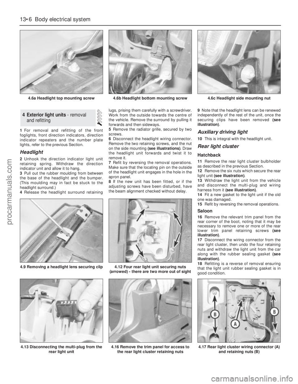
6Disconnect the headlight wiring connector.
Remove the two retaining screws, and the nut
on the side mounting (see illustrations). Draw
the headlight unit forwards and twist it to
remove it.
7Refit by reversing the removal operations.
Make sure that the locating pin on the outside
of the headlight unit engages in the hole in the
apron panel.
8If the new unit has been fitted, or if the
adjusting screws have been disturbed, have
the beam alignment checked without delay.9Note that the headlight lens can be renewed
independently of the rest of the unit, once the
securing clips have been removed (see
illustration).
Auxiliary driving light
10This is integral with the headlight unit.
Rear light cluster
Hatchback
11Remove the rear light cluster bulbholder
as described in the previous Section.
12Remove the six nuts which secure the rear
light unit (see illustration).
13Withdraw the light unit from the vehicle
and disconnect the multi-plug and wiring
harness from it (see illustration).
14Fit a new gasket to the light unit if the old
one was damaged.
15Refit by reversing the removal operations.
Saloon
16Remove the relevant trim panel from the
rear corner of the boot, noting that it may be
necessary to remove one or more of the rear
lower trim panel retaining screws (see
illustration).
17Disconnect the wiring connector from the
rear light cluster, then undo the four retaining
nuts and withdraw the light unit from the car
along with the rubber sealing gasket (see
illustration).
18Refitting is a reverse of removal ensuring
that the light unit rubber sealing gasket is in
good condition.
4Exterior light units - removal
and refitting
13•6Body electrical system
4.6a Headlight top mounting screw
4.13 Disconnecting the multi-plug from the
rear light unit
4.9 Removing a headlight lens securing clip4.12 Four rear light unit securing nuts
(arrowed) - there are two more out of sight
4.16 Remove the trim panel for access to
the rear light cluster retaining nuts4.17 Rear light cluster wiring connector (A)
and retaining nuts (B)
4.6b Headlight bottom mounting screw4.6c Headlight side mounting nut
procarmanuals.com
Page 184 of 255
Estate
19This procedure is the same as described
above for the Saloon models noting that it is
necessary to remove the luggage
compartment side trim panel to gain access to
the light cluster retaining nuts.
1It is recommended that beam adjustment be
carried out by a Ford garage using optical
alignment equipment. In an emergency,
however, the following procedure will produce
acceptable results.
2The vehicle should be normally laden and the
tyre pressures must be correct. Park the vehicle
on level ground, approximately 10 metres (33
feet) in front of a flat wall or garage door.
3Draw a vertical line on the wall or door
corresponding to the centre-line of the vehicle.
(The position of this line can be determined by
marking the centres of the windscreen and
rear window with crayon, then viewing the wall
or door from the rear of the vehicle.)
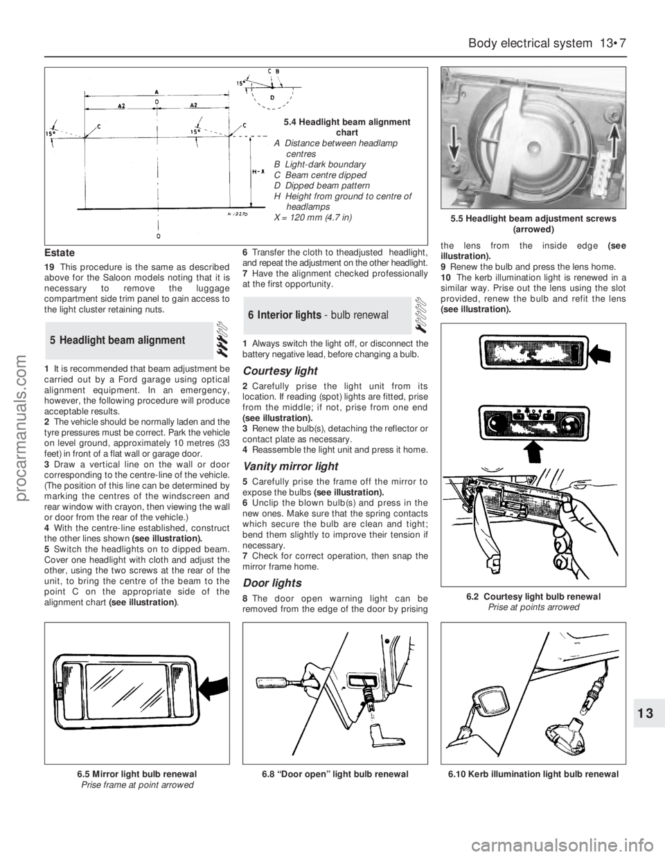
4With the centre-line established, construct
the other lines shown (see illustration).
5Switch the headlights on to dipped beam.
Cover one headlight with cloth and adjust the
other, using the two screws at the rear of the
unit, to bring the centre of the beam to the
point C on the appropriate side of the
alignment chart (see illustration).6Transfer the cloth to theadjusted headlight,
and repeat the adjustment on the other headlight.
7Have the alignment checked professionally
at the first opportunity.
1Always switch the light off, or disconnect the
battery negative lead, before changing a bulb.
Courtesy light
2Carefully prise the light unit from its
location. If reading (spot) lights are fitted, prise
from the middle; if not, prise from one end
(seeillustration).
3Renew the bulb(s), detaching the reflector or
contact plate as necessary.
4Reassemble the light unit and press it home.
Vanity mirror light
5Carefully prise the frame off the mirror to
expose the bulbs(see illustration).
6Unclip the blown bulb(s) and press in the
new ones. Make sure that the spring contacts
which secure the bulb are clean and tight;
bend them slightly to improve their tension if
necessary.
7Check for correct operation, then snap the
mirror frame home.
Door lights
8The door open warning light can be
removed from the edge of the door by prisingthe lens from the inside edge (see
illustration).
9Renew the bulb and press the lens home.
10The kerb illumination light is renewed in a
similar way. Prise out the lens using the slot
provided, renew the bulb and refit the lens
(seeillustration).
6Interior lights - bulb renewal
5Headlight beam alignment
Body electrical system 13•7
13
5.5 Headlight beam adjustment screws
(arrowed)
6.2 Courtesy light bulb renewal
Prise at points arrowed
6.8 “Door open” light bulb renewal6.5 Mirror light bulb renewal
Prise frame at point arrowed
5.4 Headlight beam alignment
chart
A Distance between headlamp
centres
B Light-dark boundary
C Beam centre dipped
D Dipped beam pattern
H Height from ground to centre of
headlamps
X = 120 mm (4.7 in)
6.10 Kerb illumination light bulb renewal
procarmanuals.com
 1
1 2
2 3
3 4
4 5
5 6
6 7
7 8
8 9
9 10
10 11
11 12
12 13
13 14
14 15
15 16
16 17
17 18
18 19
19 20
20 21
21 22
22 23
23 24
24 25
25 26
26 27
27 28
28 29
29 30
30 31
31 32
32 33
33 34
34 35
35 36
36 37
37 38
38 39
39 40
40 41
41 42
42 43
43 44
44 45
45 46
46 47
47 48
48 49
49 50
50 51
51 52
52 53
53 54
54 55
55 56
56 57
57 58
58 59
59 60
60 61
61 62
62 63
63 64
64 65
65 66
66 67
67 68
68 69
69 70
70 71
71 72
72 73
73 74
74 75
75 76
76 77
77 78
78 79
79 80
80 81
81 82
82 83
83 84
84 85
85 86
86 87
87 88
88 89
89 90
90 91
91 92
92 93
93 94
94 95
95 96
96 97
97 98
98 99
99 100
100 101
101 102
102 103
103 104
104 105
105 106
106 107
107 108
108 109
109 110
110 111
111 112
112 113
113 114
114 115
115 116
116 117
117 118
118 119
119 120
120 121
121 122
122 123
123 124
124 125
125 126
126 127
127 128
128 129
129 130
130 131
131 132
132 133
133 134
134 135
135 136
136 137
137 138
138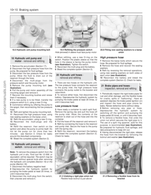 139
139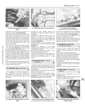 140
140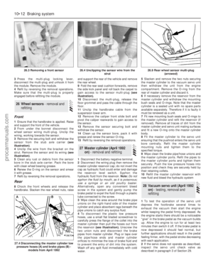 141
141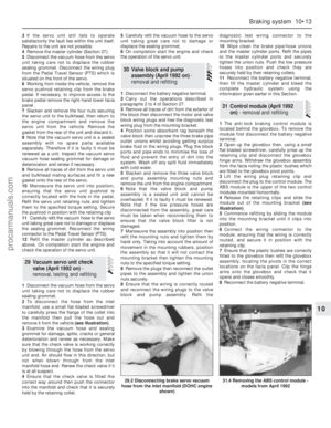 142
142 143
143 144
144 145
145 146
146 147
147 148
148 149
149 150
150 151
151 152
152 153
153 154
154 155
155 156
156 157
157 158
158 159
159 160
160 161
161 162
162 163
163 164
164 165
165 166
166 167
167 168
168 169
169 170
170 171
171 172
172 173
173 174
174 175
175 176
176 177
177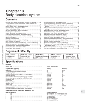 178
178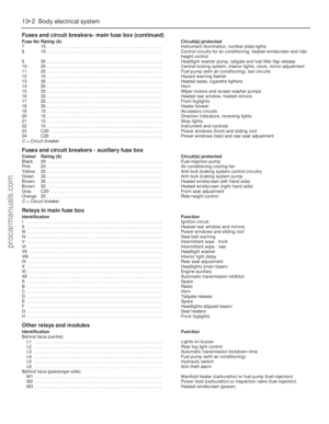 179
179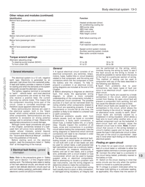 180
180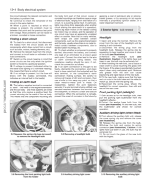 181
181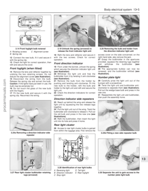 182
182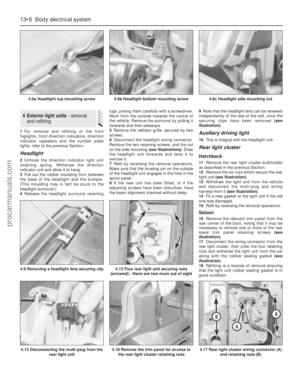 183
183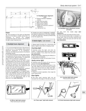 184
184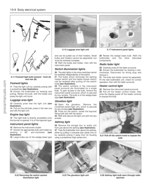 185
185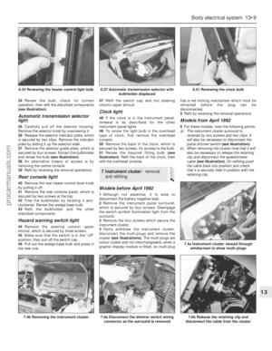 186
186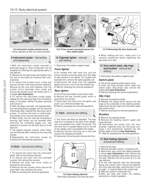 187
187 188
188 189
189 190
190 191
191 192
192 193
193 194
194 195
195 196
196 197
197 198
198 199
199 200
200 201
201 202
202 203
203 204
204 205
205 206
206 207
207 208
208 209
209 210
210 211
211 212
212 213
213 214
214 215
215 216
216 217
217 218
218 219
219 220
220 221
221 222
222 223
223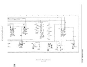 224
224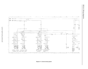 225
225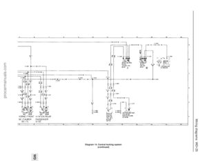 226
226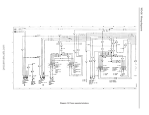 227
227 228
228 229
229 230
230 231
231 232
232 233
233 234
234 235
235 236
236 237
237 238
238 239
239 240
240 241
241 242
242 243
243 244
244 245
245 246
246 247
247 248
248 249
249 250
250 251
251 252
252 253
253 254
254