Page 17 of 255
Instruments and electrical
equipment
1Check the operation of all instruments and
electrical equipment.
2Make sure that all instruments read
correctly, and switch on all electrical
equipment in turn to check that it functions
properly.
Steering and suspension
3Check for any abnormalities in the steering,
suspension, handling or road “feel”.
4Drive the vehicle, and check that there are
no unusual vibrations or noises.
5Check that the steering feels positive, with
no excessive “sloppiness”, or roughness, and
check for any suspension noises when
cornering, or when driving over bumps.
Drivetrain
6Check the performance of the engine,
clutch, transmission and driveshafts.
7Listen for any unusual noises from the
engine, clutch and transmission.
8Make sure that the engine runs smoothly
when idling, and that there is no hesitation
when accelerating.
9Where applicable, check that the clutch
action is smooth and progressive, that the
drive is taken up smoothly, and that the pedal
travel is not excessive. Also listen for any
noises when the clutch pedal is depressed.
10Check that all gears can be engaged
smoothly, without noise, and that the gear
lever action is not abnormally vague or
“notchy”.
Check the operation and
performance of the braking system
11Make sure that the vehicle does not pull to
one side when braking, and that the wheels do
not lock prematurely when braking hard.
12Check that there is no vibration through
the steering when braking.
13Check that the handbrake operates
correctly, without excessive movement of the
lever, and that it holds the vehicle stationary
on a slope.
14Test the operation of the brake servo unit
as follows. With the engine off, depress the
footbrake four or five times to exhaust the
vacuum. Start the engine, holding the brake
pedal depressed. As the engine starts, there
should be a noticeable “give” in the brake
pedal as vacuum builds up. Allow the engine
to run for at least two minutes, and then
switch it off. If the brake pedal is depressed
now, it should be possible to detect a hiss
from the servo as the pedal is depressed. After
about four or five applications, no further
hissing should be heard, and the pedal should
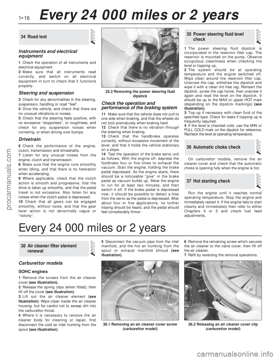
feel considerably firmer.1The power steering fluid dipstick is
incorporated in the reservoir filler cap. The
reservoir is mounted on the pump. Observe
scrupulous cleanliness when checking the
level or topping-up.
2The system should be at operating
temperature and the engine switched off.
Wipe clean around the reservoir filler cap.
Unscrew the cap, withdraw the dipstick and
wipe it with a clean lint-free rag. Reinsert the
dipstick, screw the cap home, then unscrew it
again and read the level on the dipstick. It
should be up to the MAX or upper HOT mark
(depending on the dipstick markings) (see
illustration).
3Top-up if necessary with clean fluid of the
specified type. Check for leaks if topping-up is
frequently required.
4If the level is checked cold, use the MIN or
FULL COLD mark on the dipstick for reference.
Recheck the level at operating temperature.
On carburettor models, remove the air
cleaner cover and check that the automatic
choke is opening fully when the engine is hot.
Run the engine until it reaches normal
operating temperature. Stop the engine and
immediately restart it. If the engine fails to start
cleanly and immediately then refer to either
Chapters 4 or 5 and check fuel feed
adjustments.
37Hot starting check
36Automatic choke check
35Power steering fluid level
check34Road test
Carburettor models
SOHC engines
1Remove the screws from the air cleaner
cover(see illustration).
2Release the spring clips (when fitted), then
lift off the cover (see illustration).
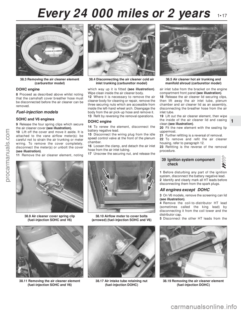
3Lift out the air cleaner element(see
illustration). Wipe clean inside the air cleaner
housing, but be careful not to sweep dirt into
the carburettor throat.
4Where it is necessary to remove the air
cleaner body for cleaning or repair, first
disconnect the cold air inlet trunking from the
spout (see illustration). 5Disconnect the vacuum pipe from the inlet
manifold, and the hot air trunking from the
spout or exhaust manifold shroud(see
illustration). 6Remove the remaining screw which secures
the air cleaner to the valve cover, then lift off
the air cleaner.
7Refit by reversing the removal operations.
38Air cleaner filter element
renewal
1•16Every 24 000 miles or 2 years
35.2 Removing the power steering fluid
dipstick
38.2 Releasing an air cleaner cover clip
(carburettor model)38.1 Removing an air cleaner cover screw
(carburettor model)
Every 24 000 miles or 2 years
procarmanuals.com
Page 18 of 255
DOHC engine
8Proceed as described above whilst noting
that the camshaft cover breather hose must
be disconnected before the air cleaner can be
removed.
Fuel-injection models
SOHC and V6 engines
9Release the four spring clips which secure
the air cleaner cover(see illustration).
10Lift off the cover and move it aside. It is
attached to the vane airflow meter(s): be
careful not to strain the air trunking or meter
wiring. To remove the cover completely,
disconnect the meter(s) or unbolt the cover
(see illustration).
11Remove the air cleaner element, notingwhich way up it is fitted (see illustration).
Wipe clean inside the air cleaner body.
12Where it is necessary to remove the air
cleaner body for cleaning or repair, remove the
three securing nuts which are accessible from
inside the left-hand wheel arch. Disengage the
body from the air pick-up hose and remove it.
13Refit by reversing the removal operations.DOHC engine
14To renewthe element, disconnect the
battery negative lead.
15Disconnect the wiring plug from the idle
speed control valve at the front of the plenum
chamber.
16Loosen the clamp, and detach the air inlet
hose from the air inlet tubing.
17Unscrew the securing nut, and release theair inlet tube from the bracket on the engine
compartment front panel (see illustration).
18Release the air cleaner lid securing clips,
then lift away the air inlet tube, plenum
chamber and air cleaner lid as an assembly,
disconnecting the breather hose from the air
inlet tube.
19Lift out the air cleaner element, then wipe
the inside of the air cleaner lid and casing
clean (see illustration).
20Fit the new element with the sealing lip
uppermost.
21Further refitting is a reversal of removal.
22To remove and refit the air cleaner
housing, refer to paragraph 12.
23Refitting is the reverse of the removal
procedure.
1Before disturbing any part of the ignition
system, disconnect the battery negative lead.
2Identify and clearly mark all HT leads before
disconnecting them from the spark plugs.
All engines except DOHC
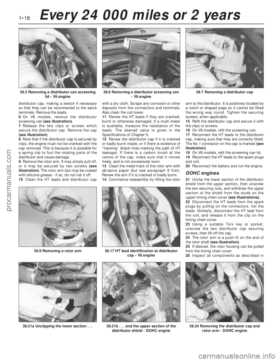
3On V6 models, remove the screening can lid
(see illustration).
4Remove the coil-to-distributor HT lead
(sometimes called the king lead) by
disconnecting it from the coil tower and the
distributor cap.
5Disconnect the other HT leads from the
39Ignition system component
check
1•17
1
Every 24 000 miles or 2 years
38.4 Disconnecting the air cleaner cold air
inlet trunking (carburettor model)38.5 Air cleaner hot air trunking and
manifold shroud (carburettor model)38.3 Removing the air cleaner element
(carburettor model)
38.17 Air intake tube retaining nut
(fuel-injection DOHC)38.19 Removing the air cleaner element
(fuel-injection DOHC)38.11 Removing the air cleaner element
(fuel-injection SOHC and V6)
38.9 Air cleaner cover spring clip
(fuel-injection SOHC and V6)38.10 Airflow meter to cover bolts
(arrowed) (fuel-injection SOHC and V6)
procarmanuals.com
Page 19 of 255
distributor cap, making a sketch if necessary
so that they can be reconnected to the same
terminals. Remove the leads.
6On V6 models, remove the distributor
screening can (see illustration).
7Release the two clips or screws which
secure the distributor cap. Remove the cap
(see illustration).
8Note that if the distributor cap is secured by
clips, the engine must not be cranked with the
cap removed. This is because it is possible for
a spring clip to foul the rotating parts of the
distributor and cause damage.
9Remove the rotor arm. It may simply pull off,
or it may be secured by two screws (see
illustration). The rotor arm tips may be coated
with silicone grease - if so, do not rub it off.
10Clean the HT leads and distributor capwith a dry cloth. Scrape any corrosion or other
deposits from the connectors and terminals.
Also clean the coil tower.
11Renew the HT leads if they are cracked,
burnt or otherwise damaged. If a multi-meter
is available, measure the resistance of the
leads. The desired value is given in the
Specifications of Chapter 5.
12Renew the distributor cap if it is cracked
or badly burnt inside, or if there is evidence of
“tracking” (black lines marking the path of HT
leakage). If there is a carbon brush at the
centre of the cap, make sure that it moves
freely, and is not excessively worn.
13Clean the metal track of the rotor arm with
abrasive paper (but see paragraph 9 first).
Renew the arm if it is cracked or badly burnt.
14Commence reassembly by fitting the rotorarm to the distributor. It is positively located by
a notch or shaped pegs so it cannot be fitted
the wrong way round. Tighten the securing
screws, when applicable.
15Refit the distributor cap and secure it with
the clips or screws.
16On V6 models, refit the screening can.
17Reconnect the HT leads to the distributor
cap, making sure that they are correctly fitted.
The No 1 connector on the cap is marked (see
illustration).
18On V6 models, refit the screening can lid.
19Reconnect the HT leads to the spark plugs
and coil.
20Reconnect the battery and run the engine.
DOHC engines
21Unclip the lower section of the distributor
shield from the upper section, then unscrew
the two securing nuts, and withdraw the upper
section of the shield from the studs on the
upper timing chain cover (see illustrations).
22Disconnect the HT leads from the spark
plugs by pulling on the connectors, not the
leads. Similarly, disconnect the HT lead from
the coil, and release it from the clip on the
timing chain cover.
23Using a suitable Torx key or socket,
unscrew the two distributor cap securing
screws, then lift off the cap.
24The rotor arm is a push-fit on the end of
the rotor shaft (see illustration).
25If desired, the rotor housing can be pulled
from the timing chain cover.
26Inspect all components as described in
1•18Every 24 000 miles or 2 years
39.6 Removing a distributor screening can
- V6 engine39.7 Removing a distributor cap39.3 Removing a distributor can screening
lid - V6 engine
39.21b . . . and the upper section of the
distributor shield - DOHC engine39.24 Removing the distributor cap and
rotor arm - DOHC engine39.21a Unclipping the lower section . . .
39.9 Removing a rotor arm39.17 HT lead identification at distributor
cap - V6 engine
procarmanuals.com
Page 20 of 255
the previous sub Section.
27Refitting is a reversal of removal, ensuring
that the rotor arm is pushed fully home on the
rotor shaft. Make sure that the HT leads are
fitted to their correct cylinders. Note that the
rotor arm will only fit in one position.
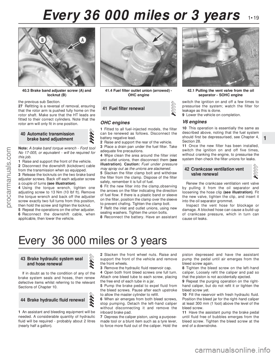
Note: A brake band torque wrench - Ford tool
No 17-005, or equivalent - will be required for
this job.
1Raise and support the front of the vehicle.
2Disconnect the downshift (kickdown) cable
from the transmission when so equipped.
3Release the locknuts on the two brake band
adjuster screws. Back off each adjuster screw
a couple of turns (see illustration).
4Using the torque wrench, tighten one
adjusting screw to 13 Nm (10 lbf ft). Remove
the torque wrench and back off the adjuster
screw exactly two full turns from this position,
then hold the screw and tighten the locknut.
5Repeat the operations on the other adjuster.
6Reconnect the downshift cable, when
applicable, then lower the vehicle.
OHC engines
1Fitted to all fuel-injected models, the filter
can be renewed as follows. Disconnect the
battery negative lead.
2Raise and support the rear of the vehicle.
3Place a drain pan under the fuel filter. Take
adequate fire precautions.
4Wipe clean the area around the filter inlet
and outlet unions, then disconnect them (see
illustration). Caution: Fuel under pressure
may spray out as the unions are slackened.
5Slacken the filter clamp bolt and withdraw
the filter from the clamp. Dispose of the filter
safely, remember it is full of fuel.
6Fit the new filter into the clamp,observing
the arrows on the filter indicating the direction
of fuel flow. If there is a plastic band or sleeve
on the filter, position the clamp over the sleeve
to prevent chafing. Tighten the clamp bolt.
7Refit the inlet and outlet unions, using new
sealing washers. Tighten the union bolts.
8Reconnect the battery. Have an assistantswitch the ignition on and off a few times to
pressurise the system; watch the filter for
leakage as this is done.
9Lower the vehicle on completion.
V6 engines
10This operation is essentially the same as
described above, noting that the fuel system
should first be depressurised, see Chapter 4,
Section 28.
11Once the new filter has been installed,
switch the ignition on and off five times,
without cranking the engine, to pressurise the
system then check the filter unions for leaks.
Renew the crankcase ventilation vent valve
by pulling it from the oil separator and
loosening the hose clip (see illustration). Fit
the new valve, tighten the clip, and insert it
into the oil separator grommet.
Inspect the vent hose for blockage or
damage. A blocked hose can cause a build-up
of crankcase pressure, which in turn can
cause oil leaks.
42Crankcase ventilation vent
valve renewal
41Fuel filter renewal
40Automatic transmission
brake band adjustment
1•19
1
Every 36 000 miles or 3 years
41.4 Fuel filter outlet union (arrowed) -
OHC engine42.1 Pulling the vent valve from the oil
separator - SOHC engine40.3 Brake band adjuster screw (A) and
locknut (B)
If in doubt as to the condition of any of the
brake system seals and hoses, then renew
defective items whilst referring to the relevant
Sections of Chapter 10.
1An assistant andbleeding equipment will be
needed. A considerable quantity of hydraulic
fluid will be required - probably about 2 litres
(nearly half a gallon).2Slacken the front wheel nuts. Raise and
support the front of the vehicle andremove
the front wheels.
3Remove the hydraulic fluid reservoir cap.
4Open both front bleed screws one full turn.
Attach one bleed tube to each screw, placing
the free end of each tube in a jar.
5Pump the brake pedal to expel fluid from
the bleed screws. Pause after each upstroke
to allow the master cylinder to refill.
6When air emerges from both bleed screws,
stop pumping. Detach the left-hand caliper
without disconnecting it and remove the
inboard brake pad.
7Depress the caliper piston, using a purpose-
made tool or a blunt item such as a tyre lever,
to force more fluid out of the caliper. Hold thepiston depressed and have the assistant
pump the pedal until air emerges from the
bleed screw again.
8Tighten the bleed screw on the left-hand
caliper. Loosely refit the caliper and pad so
that the piston is not accidentally ejected.
9Repeat the purging operation on the right-
hand caliper, but do not refit it or tighten the
bleed screw yet.
10Fill the reservoir with fresh hydraulic fluid.
Position the bleed jar for the right-hand caliper
at least 300 mm (1 foot) above the level of the
bleed screw.
11Have the assistant pump the brake pedal
until fluid free of bubbles emerges from the
bleed screw. Tighten the bleed screw at the
end of a downstroke.
44Brake hydraulic fluid renewal
43Brake hydraulic system seal
and hose renewal
Every 36 000 miles or 3 years
procarmanuals.com
Page 21 of 255
12Place a piece of wood in the caliper jaws
to limit piston travel. Keep your fingers clear of
the piston. Have the assistant depress the
brake pedal gentlyin order to move the
caliper piston out.
13With the pedal held depressed, slacken
the bleed screw on the right-hand caliper and
again depress the piston. Tighten the bleed
screw when the piston is retracted. The pedal
can now be released.
14Disconnect the bleed tube. Refit the right-hand brake pad and caliper.
15Remove the left-hand caliper and inboard
pad again. Carry out the operations described
in paragraphs 10 to 14 on the left-hand
caliper.
16Bleed the rear brakes as described in
Chapter 10.
17Refit the front wheels, lower the vehicle
and tighten the wheel nuts.
18Pump the brake pedal to bring the pads
up to the discs, then make a final check of thehydraulic fluid level. Top-up and refit the
reservoir cap.
Camshaft drivebelt renewal is
recommended as a precautionary measure.
Refer to Chapter 2, Part A, Sections 13 and 45
for the full renewal procedure.
45Camshaft drivebelt renewal -
SOHC engines
1Before proceeding, note the precautions
given in Chapter 3, Section 1.
2Disconnect the battery negative lead.
3Remove the expansion tank cap. Take
precautions against scalding if the system is
hot.
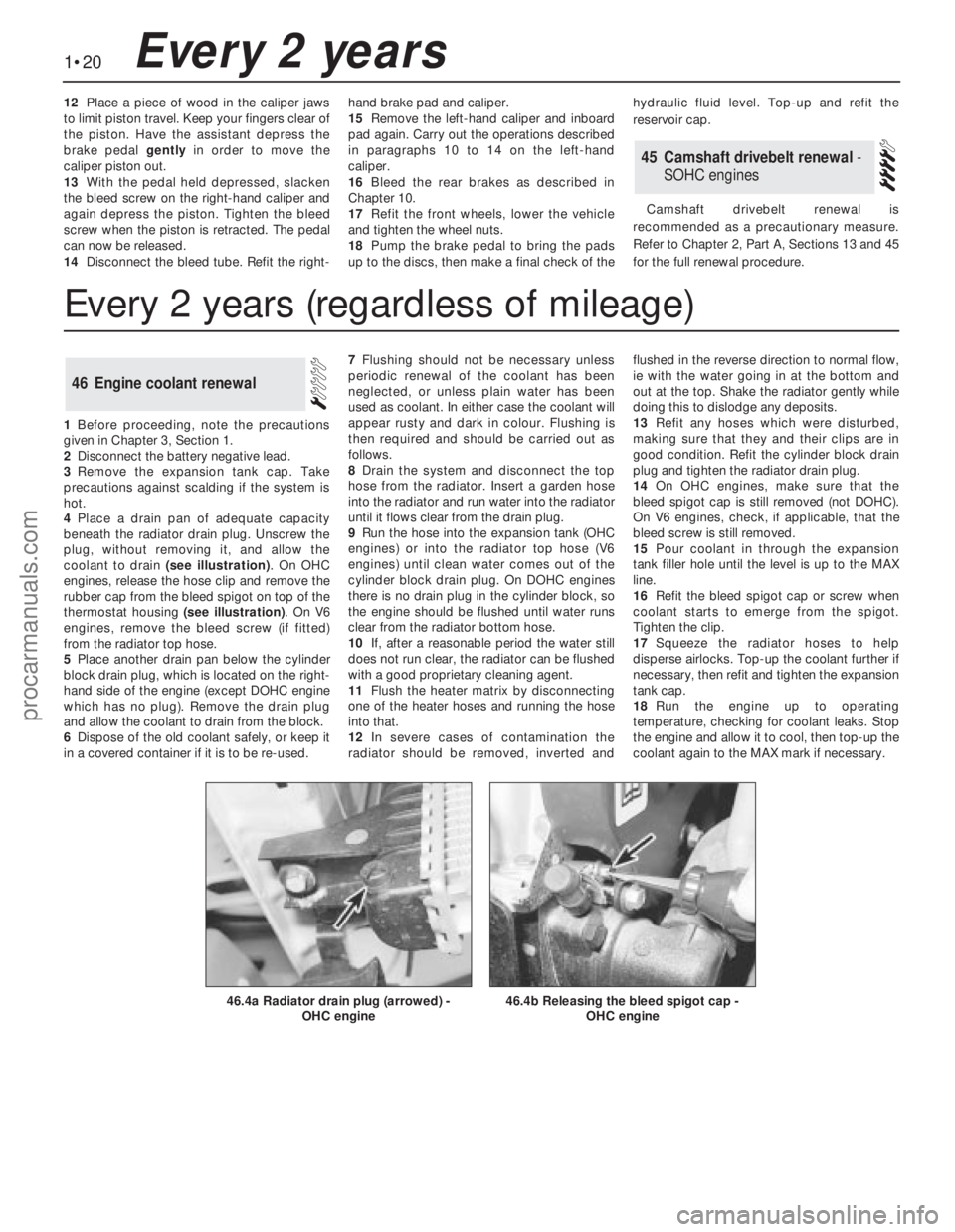
4Place a drain pan of adequate capacity
beneath the radiator drain plug. Unscrew the
plug, without removing it, and allow the
coolant to drain (see illustration). On OHC
engines, release the hose clip and remove the
rubber cap from the bleed spigot on top of the
thermostat housing (see illustration). On V6
engines, remove the bleed screw (if fitted)
from the radiator top hose.
5Place another drain pan below the cylinder
block drain plug, which is located on the right-
hand side of the engine (except DOHC engine
which has no plug). Remove the drain plug
and allow the coolant to drain from the block.
6Dispose of the old coolant safely, or keep it
in a covered container if it is to be re-used.7Flushing should not be necessary unless
periodic renewal of the coolant has been
neglected, or unless plain water has been
used as coolant. In either case the coolant will
appear rusty and dark in colour. Flushing is
then required and should be carried out as
follows.
8Drain the system and disconnect the top
hose from the radiator. Insert a garden hose
into the radiator and run water into the radiator
until it flows clear from the drain plug.
9Run the hose into the expansion tank (OHC
engines) or into the radiator top hose (V6
engines) until clean water comes out of the
cylinder block drain plug. On DOHC engines
there is no drain plug in the cylinder block, so
the engine should be flushed until water runs
clear from the radiator bottom hose.
10If, after a reasonable period the water still
does not run clear, the radiator can be flushed
with a good proprietary cleaning agent.
11Flush the heater matrix by disconnecting
one of the heater hoses and running the hose
into that.
12In severe cases of contamination the
radiator should be removed, inverted andflushed in the reverse direction to normal flow,
ie with the water going in at the bottom and
out at the top. Shake the radiator gently while
doing this to dislodge any deposits.
13Refit any hoses which were disturbed,
making sure that they and their clips are in
good condition. Refit the cylinder block drain
plug and tighten the radiator drain plug.
14On OHC engines, make sure that the
bleed spigot cap is still removed (not DOHC).
On V6 engines, check, if applicable, that the
bleed screw is still removed.
15Pour coolant in through the expansion
tank filler hole until the level is up to the MAX
line.
16Refit the bleed spigot cap or screw when
coolant starts to emerge from the spigot.
Tighten the clip.
17Squeeze the radiator hoses to help
disperse airlocks. Top-up the coolant further if
necessary, then refit and tighten the expansion
tank cap.
18Run the engine up to operating
temperature, checking for coolant leaks. Stop
the engine and allow it to cool, then top-up the
coolant again to the MAX mark if necessary.
46Engine coolant renewal
1•20Every 2 years
46.4b Releasing the bleed spigot cap -
OHC engine46.4a Radiator drain plug (arrowed) -
OHC engine
Every 2 years (regardless of mileage)
procarmanuals.com
Page 22 of 255
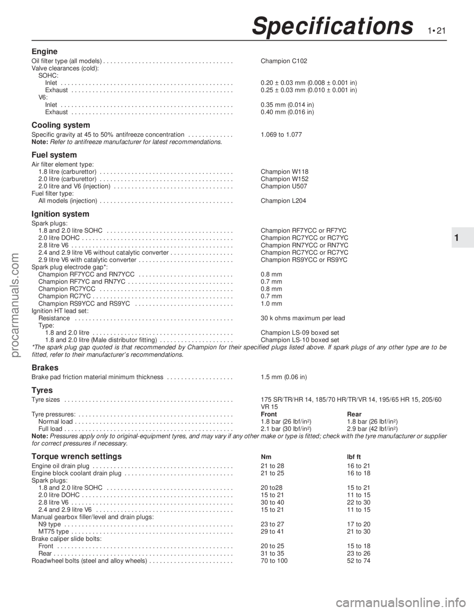
Engine
Oil filter type (all models) . . . . . . . . . . . . . . . . . . . . . . . . . . . . . . . . . . . . .Champion C102
Valve clearances (cold):
SOHC:
Inlet . . . . . . . . . . . . . . . . . . . . . . . . . . . . . . . . . . . . . . . . . . . . . . . . .0.20 ±0.03 mm (0.008 ±0.001 in)
Exhaust . . . . . . . . . . . . . . . . . . . . . . . . . . . . . . . . . . . . . . . . . . . . . .0.25 ±0.03 mm (0.010 ±0.001 in)
V6:
Inlet . . . . . . . . . . . . . . . . . . . . . . . . . . . . . . . . . . . . . . . . . . . . . . . . .0.35 mm (0.014 in)
Exhaust . . . . . . . . . . . . . . . . . . . . . . . . . . . . . . . . . . . . . . . . . . . . . .0.40 mm (0.016 in)
Cooling system
Specific gravity at 45 to 50% antifreeze concentration . . . . . . . . . . . . .1.069 to 1.077
Note:Refer to antifreeze manufacturer for latest recommendations.
Fuel system
Air filter element type:
1.8 litre (carburettor) . . . . . . . . . . . . . . . . . . . . . . . . . . . . . . . . . . . . . .Champion W118
2.0 litre (carburettor) . . . . . . . . . . . . . . . . . . . . . . . . . . . . . . . . . . . . . .Champion W152
2.0 litre and V6 (injection) . . . . . . . . . . . . . . . . . . . . . . . . . . . . . . . . . .Champion U507
Fuel filter type:
All models (injection) . . . . . . . . . . . . . . . . . . . . . . . . . . . . . . . . . . . . . .Champion L204
Ignition system
Spark plugs:
1.8 and 2.0 litre SOHC . . . . . . . . . . . . . . . . . . . . . . . . . . . . . . . . . . . .Champion RF7YCC or RF7YC
2.0 litre DOHC . . . . . . . . . . . . . . . . . . . . . . . . . . . . . . . . . . . . . . . . . . .Champion RC7YCC or RC7YC
2.8 litre V6 . . . . . . . . . . . . . . . . . . . . . . . . . . . . . . . . . . . . . . . . . . . . . .Champion RN7YCC or RN7YC
2.4 and 2.9 litre V6 without catalytic converter . . . . . . . . . . . . . . . . . .Champion RC7YCC or RC7YC
2.9 litre V6 with catalytic converter . . . . . . . . . . . . . . . . . . . . . . . . . . .Champion RS9YCC or RS9YC
Spark plug electrode gap*:
Champion RF7YCC and RN7YCC . . . . . . . . . . . . . . . . . . . . . . . . . . .0.8 mm
Champion RF7YC and RN7YC . . . . . . . . . . . . . . . . . . . . . . . . . . . . . .0.7 mm
Champion RC7YCC . . . . . . . . . . . . . . . . . . . . . . . . . . . . . . . . . . . . . .0.8 mm
Champion RC7YC . . . . . . . . . . . . . . . . . . . . . . . . . . . . . . . . . . . . . . . .0.7 mm
Champion RS9YCC and RS9YC . . . . . . . . . . . . . . . . . . . . . . . . . . . .1.0 mm
Ignition HT lead set:
Resistance . . . . . . . . . . . . . . . . . . . . . . . . . . . . . . . . . . . . . . . . . . . . .30 k ohms maximum per lead
Type:
1.8 and 2.0 litre . . . . . . . . . . . . . . . . . . . . . . . . . . . . . . . . . . . . . . . .Champion LS-09 boxed set
1.8 and 2.0 litre (Male distributor fitting) . . . . . . . . . . . . . . . . . . . . .Champion LS-10 boxed set
*The spark plug gap quoted is that recommended by Champion for their specified plugs listed above. If spark plugs of any other type are to be
fitted, refer to their manufacturer’s recommendations.
Brakes
Brake pad friction material minimum thickness . . . . . . . . . . . . . . . . . . .1.5 mm (0.06 in)
Tyres
Tyre sizes . . . . . . . . . . . . . . . . . . . . . . . . . . . . . . . . . . . . . . . . . . . . . . . .175 SR/TR/HR 14, 185/70 HR/TR/VR 14,195/65 HR 15, 205/60
VR 15
Tyre pressures: . . . . . . . . . . . . . . . . . . . . . . . . . . . . . . . . . . . . . . . . . . . .FrontRear
Normal load . . . . . . . . . . . . . . . . . . . . . . . . . . . . . . . . . . . . . . . . . . . . .1.8 bar (26 lbf/in
2)1.8 bar (26 lbf/in2)
Full load . . . . . . . . . . . . . . . . . . . . . . . . . . . . . . . . . . . . . . . . . . . . . . . .2.1 bar (30 lbf/in2)2.9 bar (42 lbf/in2)
Note:Pressures apply only to original-equipment tyres, and may vary if any other make or type is fitted; check with the tyre manufacturer or supplier
for correct pressures if necessary.
Torque wrench settingsNmlbf ft
Engine oil drain plug . . . . . . . . . . . . . . . . . . . . . . . . . . . . . . . . . . . . . . . .21 to 2816 to 21
Engine block coolant drain plug . . . . . . . . . . . . . . . . . . . . . . . . . . . . . . .21 to 2516 to 18
Spark plugs:
1.8 and 2.0 litre SOHC . . . . . . . . . . . . . . . . . . . . . . . . . . . . . . . . . . . .20 to2815 to 21
2.0 litre DOHC . . . . . . . . . . . . . . . . . . . . . . . . . . . . . . . . . . . . . . . . . . .15 to 2111 to 15
2.8 litre V6 . . . . . . . . . . . . . . . . . . . . . . . . . . . . . . . . . . . . . . . . . . . . . .30 to 4022 to 30
2.4 and 2.9 litre V6 . . . . . . . . . . . . . . . . . . . . . . . . . . . . . . . . . . . . . . .15 to 2111 to 15
Manual gearbox filler/level and drain plugs:
N9 type . . . . . . . . . . . . . . . . . . . . . . . . . . . . . . . . . . . . . . . . . . . . . . . .23 to 2717 to 20
MT75 type . . . . . . . . . . . . . . . . . . . . . . . . . . . . . . . . . . . . . . . . . . . . . .29 to 4121 to 30
Brake caliper slide bolts:
Front . . . . . . . . . . . . . . . . . . . . . . . . . . . . . . . . . . . . . . . . . . . . . . . . . .20 to 2515 to 18
Rear . . . . . . . . . . . . . . . . . . . . . . . . . . . . . . . . . . . . . . . . . . . . . . . . . . .31 to 3523 to 26
Roadwheel bolts (steel and alloy wheels) . . . . . . . . . . . . . . . . . . . . . . . .70 to 10052 to 74
1•21
1
Specifications
procarmanuals.com
Page 23 of 255
1•22Notes
procarmanuals.com
Page 24 of 255
Chapter 2 Part A:
1.8 & 2.0 litre SOHC engines
Ancillary components - refitting . . . . . . . . . . . . . . . . . . . . . . . . . . . .46
Ancillary components - removal . . . . . . . . . . . . . . . . . . . . . . . . . . . . .9
Auxiliary shaft - examination and renovation . . . . . . . . . . . . . . . . . .31
Auxiliary shaft - refitting . . . . . . . . . . . . . . . . . . . . . . . . . . . . . . . . . .41
Auxiliary shaft - removal . . . . . . . . . . . . . . . . . . . . . . . . . . . . . . . . . .14
Camshaft and cam followers - examination and renovation . . . . . .30
Camshaft - refitting . . . . . . . . . . . . . . . . . . . . . . . . . . . . . . . . . . . . . .43
Camshaft - removal . . . . . . . . . . . . . . . . . . . . . . . . . . . . . . . . . . . . .11
Compression test - description and interpretation . . . . . . . . . . . . .52
Crankcase ventilation system - general information . . . . . . . . . . . .24
Crankshaft and bearings - examination and renovation . . . . . . . . .27
Crankshaft and main bearings - refitting . . . . . . . . . . . . . . . . . . . . .36
Crankshaft and main bearings - removal . . . . . . . . . . . . . . . . . . . . .22
Crankshaft front oil seal - renewal . . . . . . . . . . . . . . . . . . . . . . . . . .17
Crankshaft rear oil seal - renewal . . . . . . . . . . . . . . . . . . . . . . . . . . .18
Cylinder block and bores - examination and renovation . . . . . . . . .28
Cylinder head - decarbonising, valve grinding and renovation . . . .34
Cylinder head - dismantling . . . . . . . . . . . . . . . . . . . . . . . . . . . . . . .12
Cylinder head - reassembly . . . . . . . . . . . . . . . . . . . . . . . . . . . . . . .42
Cylinder head - refitting . . . . . . . . . . . . . . . . . . . . . . . . . . . . . . . . . .44
Cylinder head - removal . . . . . . . . . . . . . . . . . . . . . . . . . . . . . . . . . .10
Engine and gearbox - reconnection . . . . . . . . . . . . . . . . . . . . . . . . .47
Engine dismantling - general information . . . . . . . . . . . . . . . . . . . . . .8
Engine mountings - renewal . . . . . . . . . . . . . . . . . . . . . . . . . . . . . . .23
Engine reassembly - general information . . . . . . . . . . . . . . . . . . . . .35
Engine - refitting without gearbox/transmission . . . . . . . . . . . . . . .49Engine - refitting with manual gearbox . . . . . . . . . . . . . . . . . . . . . . .48
Engine - removal leaving gearbox/transmission in vehicle . . . . . . . .5
Engine - removal with manual gearbox . . . . . . . . . . . . . . . . . . . . . . .6
Engine - separation from manual gearbox . . . . . . . . . . . . . . . . . . . . .7
Examination and renovation - general information . . . . . . . . . . . . .25
Flywheel/driveplate and adapter plate - refitting . . . . . . . . . . . . . . .40
Flywheel/driveplate and adapter plate - removal . . . . . . . . . . . . . . .15
Flywheel ring gear - examination and renovation . . . . . . . . . . . . . .33
General information . . . . . . . . . . . . . . . . . . . . . . . . . . . . . . . . . . . . . .1
Initial start-up after overhaul or major repair . . . . . . . . . . . . . . . . . .51
Major operations possible with the engine in the vehicle . . . . . . . . .2
Major operations requiring engine removal . . . . . . . . . . . . . . . . . . . .3
Methods of engine removal . . . . . . . . . . . . . . . . . . . . . . . . . . . . . . . .4
Oil filter - renewal . . . . . . . . . . . . . . . . . . . . . . . . . . . . . . . . . . . . . . .20
Oil pump - examination and renovation . . . . . . . . . . . . . . . . . . . . . .26
Oil pump - refitting . . . . . . . . . . . . . . . . . . . . . . . . . . . . . . . . . . . . . .38
Oil pump - removal . . . . . . . . . . . . . . . . . . . . . . . . . . . . . . . . . . . . . .19
Pistons and connecting rods - examination and renovation . . . . . .29
Pistons and connecting rods - refitting . . . . . . . . . . . . . . . . . . . . . .37
Pistons and connecting rods - removal . . . . . . . . . . . . . . . . . . . . . .21
Sump - refitting . . . . . . . . . . . . . . . . . . . . . . . . . . . . . . . . . . . . . . . . .39
Sump - removal . . . . . . . . . . . . . . . . . . . . . . . . . . . . . . . . . . . . . . . .16
Timing belt - examination and renovation . . . . . . . . . . . . . . . . . . . .32
Timing belt and sprockets - refitting . . . . . . . . . . . . . . . . . . . . . . . . 45
Timing belt and sprockets - removal . . . . . . . . . . . . . . . . . . . . . . . .13
Valve clearances - checking and adjustment . . . . . . . . . . . . . . . . . .50
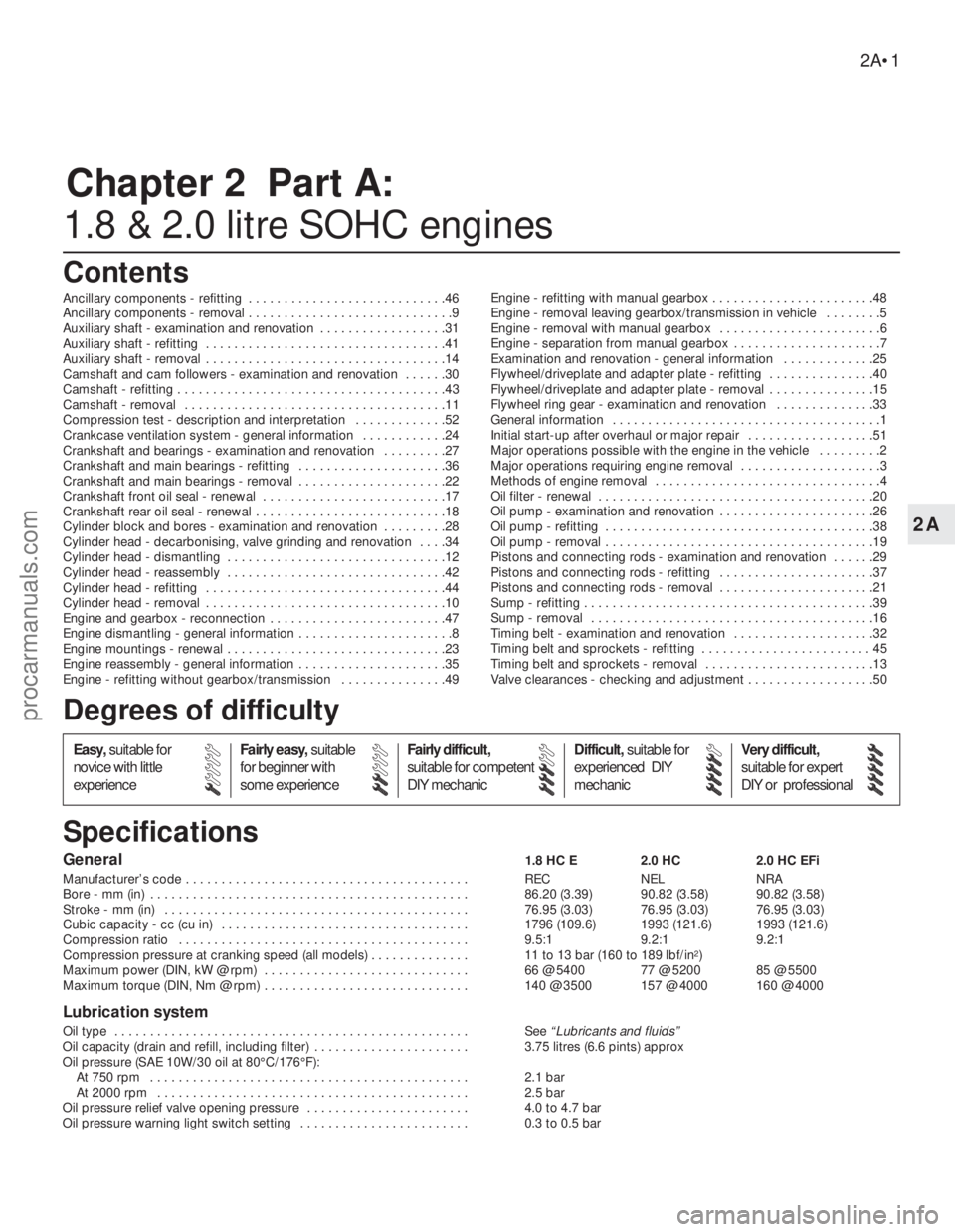
General1.8 HC E 2.0 HC 2.0 HC EFi
Manufacturer’s code . . . . . . . . . . . . . . . . . . . . . . . . . . . . . . . . . . . . . . . . REC NEL NRA
Bore - mm (in) . . . . . . . . . . . . . . . . . . . . . . . . . . . . . . . . . . . . . . . . . . . . . 86.20 (3.39) 90.82 (3.58) 90.82 (3.58)
Stroke - mm (in) . . . . . . . . . . . . . . . . . . . . . . . . . . . . . . . . . . . . . . . . . . . 76.95 (3.03) 76.95 (3.03) 76.95 (3.03)
Cubic capacity - cc (cu in) . . . . . . . . . . . . . . . . . . . . . . . . . . . . . . . . . . . 1796 (109.6) 1993 (121.6) 1993 (121.6)
Compression ratio . . . . . . . . . . . . . . . . . . . . . . . . . . . . . . . . . . . . . . . . . 9.5:1 9.2:1 9.2:1
Compression pressure at cranking speed (all models) . . . . . . . . . . . . . . 11 to 13 bar (160 to 189 lbf/in
2)
Maximum power (DIN, kW @ rpm) . . . . . . . . . . . . . . . . . . . . . . . . . . . . . 66 @ 5400 77 @ 5200 85 @ 5500
Maximum torque (DIN, Nm @ rpm) . . . . . . . . . . . . . . . . . . . . . . . . . . . . . 140 @ 3500 157 @ 4000 160 @ 4000
Lubrication system
Oil type . . . . . . . . . . . . . . . . . . . . . . . . . . . . . . . . . . . . . . . . . . . . . . . . . . See“Lubricants and fluids”
Oil capacity (drain and refill, including filter) . . . . . . . . . . . . . . . . . . . . . . 3.75 litres (6.6 pints) approx
Oil pressure (SAE 10W/30 oil at 80°C/176°F):
At 750 rpm . . . . . . . . . . . . . . . . . . . . . . . . . . . . . . . . . . . . . . . . . . . . . 2.1 bar
At 2000 rpm . . . . . . . . . . . . . . . . . . . . . . . . . . . . . . . . . . . . . . . . . . . . 2.5 bar
Oil pressure relief valve opening pressure . . . . . . . . . . . . . . . . . . . . . . . 4.0 to 4.7 bar
Oil pressure warning light switch setting . . . . . . . . . . . . . . . . . . . . . . . . 0.3 to 0.5 bar
2A•1
Easy,suitable for
novice with little
experienceFairly easy,suitable
for beginner with
some experienceFairly difficult,
suitable for competent
DIY mechanicDifficult,suitable for
experienced DIY
mechanicVery difficult,
suitable for expert
DIY or professional
Degrees of difficulty
Specifications Contents
2A
procarmanuals.com
 1
1 2
2 3
3 4
4 5
5 6
6 7
7 8
8 9
9 10
10 11
11 12
12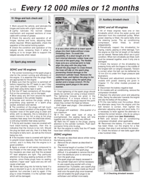 13
13 14
14 15
15 16
16 17
17 18
18 19
19 20
20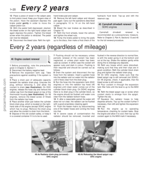 21
21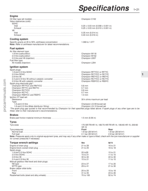 22
22 23
23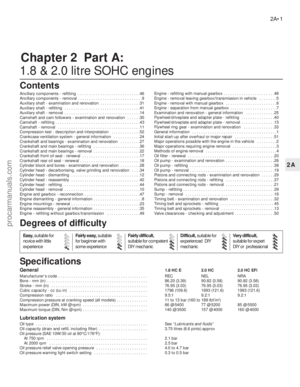 24
24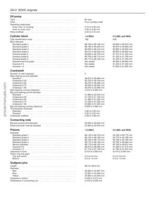 25
25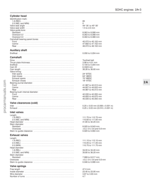 26
26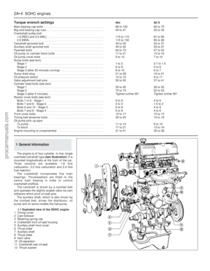 27
27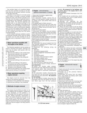 28
28 29
29 30
30 31
31 32
32 33
33 34
34 35
35 36
36 37
37 38
38 39
39 40
40 41
41 42
42 43
43 44
44 45
45 46
46 47
47 48
48 49
49 50
50 51
51 52
52 53
53 54
54 55
55 56
56 57
57 58
58 59
59 60
60 61
61 62
62 63
63 64
64 65
65 66
66 67
67 68
68 69
69 70
70 71
71 72
72 73
73 74
74 75
75 76
76 77
77 78
78 79
79 80
80 81
81 82
82 83
83 84
84 85
85 86
86 87
87 88
88 89
89 90
90 91
91 92
92 93
93 94
94 95
95 96
96 97
97 98
98 99
99 100
100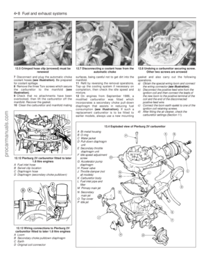 101
101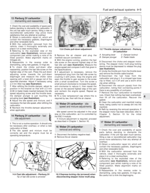 102
102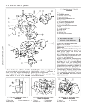 103
103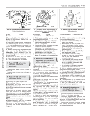 104
104 105
105 106
106 107
107 108
108 109
109 110
110 111
111 112
112 113
113 114
114 115
115 116
116 117
117 118
118 119
119 120
120 121
121 122
122 123
123 124
124 125
125 126
126 127
127 128
128 129
129 130
130 131
131 132
132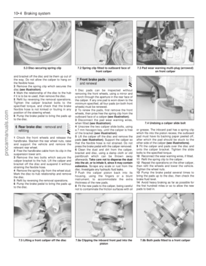 133
133 134
134 135
135 136
136 137
137 138
138 139
139 140
140 141
141 142
142 143
143 144
144 145
145 146
146 147
147 148
148 149
149 150
150 151
151 152
152 153
153 154
154 155
155 156
156 157
157 158
158 159
159 160
160 161
161 162
162 163
163 164
164 165
165 166
166 167
167 168
168 169
169 170
170 171
171 172
172 173
173 174
174 175
175 176
176 177
177 178
178 179
179 180
180 181
181 182
182 183
183 184
184 185
185 186
186 187
187 188
188 189
189 190
190 191
191 192
192 193
193 194
194 195
195 196
196 197
197 198
198 199
199 200
200 201
201 202
202 203
203 204
204 205
205 206
206 207
207 208
208 209
209 210
210 211
211 212
212 213
213 214
214 215
215 216
216 217
217 218
218 219
219 220
220 221
221 222
222 223
223 224
224 225
225 226
226 227
227 228
228 229
229 230
230 231
231 232
232 233
233 234
234 235
235 236
236 237
237 238
238 239
239 240
240 241
241 242
242 243
243 244
244 245
245 246
246 247
247 248
248 249
249 250
250 251
251 252
252 253
253 254
254


