Page 25 of 255
2A•2SOHCengines
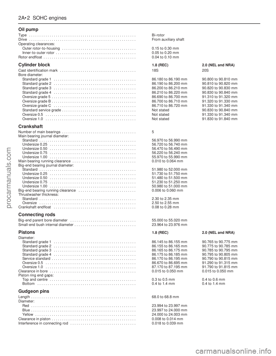
Oil pump
Type . . . . . . . . . . . . . . . . . . . . . . . . . . . . . . . . . . . . . . . . . . . . . . . . . . . .Bi-rotor
Drive . . . . . . . . . . . . . . . . . . . . . . . . . . . . . . . . . . . . . . . . . . . . . . . . . . . .From auxiliary shaft
Operating clearances:
Outer rotor-to-housing . . . . . . . . . . . . . . . . . . . . . . . . . . . . . . . . . . . .0.15 to 0.30 mm
Inner-to-outer rotor . . . . . . . . . . . . . . . . . . . . . . . . . . . . . . . . . . . . . . .0.05 to 0.20 mm
Rotor endfloat . . . . . . . . . . . . . . . . . . . . . . . . . . . . . . . . . . . . . . . . . . . . .0.04 to 0.10 mm
Cylinder block1.8 (REC)2.0 (NEL and NRA)
Cast identification mark . . . . . . . . . . . . . . . . . . . . . . . . . . . . . . . . . . . . .18S20S
Bore diameter:
Standard grade 1 . . . . . . . . . . . . . . . . . . . . . . . . . . . . . . . . . . . . . . . .86.180 to 86.190 mm90.800 to 90.810 mm
Standard grade 2 . . . . . . . . . . . . . . . . . . . . . . . . . . . . . . . . . . . . . . . .86.190 to 86.200 mm90.810 to 90.820 mm
Standard grade 3 . . . . . . . . . . . . . . . . . . . . . . . . . . . . . . . . . . . . . . . .86.200 to 86.210 mm90.820 to 90.830 mm
Standard grade 4 . . . . . . . . . . . . . . . . . . . . . . . . . . . . . . . . . . . . . . . .86.210 to 86.220 mm90.830 to 90.840 mm
Oversize grade 5 . . . . . . . . . . . . . . . . . . . . . . . . . . . . . . . . . . . . . . . . .86.690 to 86.700 mm91.310 to 91.320 mm
Oversize grade B . . . . . . . . . . . . . . . . . . . . . . . . . . . . . . . . . . . . . . . . .86.700 to 86.710 mm91.320 to 91.330 mm
Oversize grade C . . . . . . . . . . . . . . . . . . . . . . . . . . . . . . . . . . . . . . . .86.710 to 86.720 mm91.330 to 91.340 mm
Standard service grade . . . . . . . . . . . . . . . . . . . . . . . . . . . . . . . . . . . .Not stated90.830 to 90.840 mm
Oversize 0.5 . . . . . . . . . . . . . . . . . . . . . . . . . . . . . . . . . . . . . . . . . . . .Not stated91.330 to 91.340 mm
Oversize 1.0 . . . . . . . . . . . . . . . . . . . . . . . . . . . . . . . . . . . . . . . . . . . .Not stated91.830 to 91.840 mm
Crankshaft
Number of main bearings . . . . . . . . . . . . . . . . . . . . . . . . . . . . . . . . . . . .5
Main bearing journal diameter:
Standard . . . . . . . . . . . . . . . . . . . . . . . . . . . . . . . . . . . . . . . . . . . . . . .56.970 to 56.990 mm
Undersize 0.25 . . . . . . . . . . . . . . . . . . . . . . . . . . . . . . . . . . . . . . . . . .56.720 to 56.740 mm
Undersize 0.50 . . . . . . . . . . . . . . . . . . . . . . . . . . . . . . . . . . . . . . . . . .56.470 to 56.490 mm
Undersize 0.75 . . . . . . . . . . . . . . . . . . . . . . . . . . . . . . . . . . . . . . . . . .56.220 to 56.240 mm
Undersize 1.00 . . . . . . . . . . . . . . . . . . . . . . . . . . . . . . . . . . . . . . . . . .55.970 to 55.990 mm
Main bearing running clearance . . . . . . . . . . . . . . . . . . . . . . . . . . . . . . .0.010 to 0.064 mm
Big-end bearing journal diameter:
Standard . . . . . . . . . . . . . . . . . . . . . . . . . . . . . . . . . . . . . . . . . . . . . . .51.980 to 52.000 mm
Undersize 0.25 . . . . . . . . . . . . . . . . . . . . . . . . . . . . . . . . . . . . . . . . . .51.730 to 51.750 mm
Undersize 0.50 . . . . . . . . . . . . . . . . . . . . . . . . . . . . . . . . . . . . . . . . . .51.480 to 51.500 mm
Undersize 0.75 . . . . . . . . . . . . . . . . . . . . . . . . . . . . . . . . . . . . . . . . . .51.230 to 51.250 mm
Undersize 1.00 . . . . . . . . . . . . . . . . . . . . . . . . . . . . . . . . . . . . . . . . . .50.980 to 51.000 mm
Big-end bearing running clearance . . . . . . . . . . . . . . . . . . . . . . . . . . . .0.006 to 0.060 mm
Thrustwasher thickness:
Standard . . . . . . . . . . . . . . . . . . . . . . . . . . . . . . . . . . . . . . . . . . . . . . .2.30 to 2.35 mm
Oversize . . . . . . . . . . . . . . . . . . . . . . . . . . . . . . . . . . . . . . . . . . . . . . .2.50 to 2.55 mm
Crankshaft endfloat . . . . . . . . . . . . . . . . . . . . . . . . . . . . . . . . . . . . . . . .0.08 to 0.28 mm
Connecting rods
Big-end parent bore diameter . . . . . . . . . . . . . . . . . . . . . . . . . . . . . . . .55.000 to 55.020 mm
Small-end bush internal diameter . . . . . . . . . . . . . . . . . . . . . . . . . . . . . .23.964 to 23.976 mm
Pistons1.8 (REC)2.0 (NEL and NRA)
Diameter:
Standard grade 1 . . . . . . . . . . . . . . . . . . . . . . . . . . . . . . . . . . . . . . . .86.145 to 86.155 mm90.765 to 90.775 mm
Standard grade 2 . . . . . . . . . . . . . . . . . . . . . . . . . . . . . . . . . . . . . . . .86.155 to 86.165 mm90.775 to 90.785 mm
Standard grade 3 . . . . . . . . . . . . . . . . . . . . . . . . . . . . . . . . . . . . . . . .86.165 to 86.175 mm90.785 to 90.795 mm
Standard grade 4 . . . . . . . . . . . . . . . . . . . . . . . . . . . . . . . . . . . . . . . .86.175 to 86.185 mm90.795 to 90.805 mm
Service standard . . . . . . . . . . . . . . . . . . . . . . . . . . . . . . . . . . . . . . . . .86.170 to 86.195 mm90.790 to 90.815 mm
Oversize 0.5 . . . . . . . . . . . . . . . . . . . . . . . . . . . . . . . . . . . . . . . . . . . .86.670 to 86.695 mm91.290 to 91.315 mm
Oversize 1.0 . . . . . . . . . . . . . . . . . . . . . . . . . . . . . . . . . . . . . . . . . . . .87.170 to 87.195 mm91.790 to 91.815 mm
Clearance in bore . . . . . . . . . . . . . . . . . . . . . . . . . . . . . . . . . . . . . . . . . .0.015 to 0.050 mm0.015 to 0.050 mm
Piston ring end gaps:
Top and centre . . . . . . . . . . . . . . . . . . . . . . . . . . . . . . . . . . . . . . . . . .0.3 to 0.5 mm0.4 to 0.6 mm
Bottom . . . . . . . . . . . . . . . . . . . . . . . . . . . . . . . . . . . . . . . . . . . . . . . .0.4 to 1.4 mm0.4 to 1.4 mm
Gudgeon pins
Length . . . . . . . . . . . . . . . . . . . . . . . . . . . . . . . . . . . . . . . . . . . . . . . . . . .68.0 to 68.8 mm
Diameter:
Red . . . . . . . . . . . . . . . . . . . . . . . . . . . . . . . . . . . . . . . . . . . . . . . . . . .23.994 to 23.997 mm
Blue . . . . . . . . . . . . . . . . . . . . . . . . . . . . . . . . . . . . . . . . . . . . . . . . . . .23.997 to 24.000 mm
Yellow . . . . . . . . . . . . . . . . . . . . . . . . . . . . . . . . . . . . . . . . . . . . . . . . .24.000 to 24.003 mm
Clearance in piston . . . . . . . . . . . . . . . . . . . . . . . . . . . . . . . . . . . . . . . . .0.008 to 0.014 mm
Interference in connecting rod . . . . . . . . . . . . . . . . . . . . . . . . . . . . . . . .0.018 to 0.039 mm
procarmanuals.com
Page 26 of 255
SOHCengines 2A•3
2A
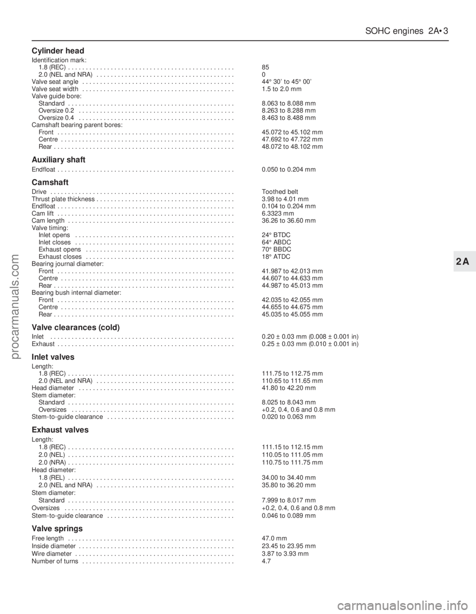
Cylinder head
Identification mark:
1.8 (REC) . . . . . . . . . . . . . . . . . . . . . . . . . . . . . . . . . . . . . . . . . . . . . . .85
2.0 (NEL and NRA) . . . . . . . . . . . . . . . . . . . . . . . . . . . . . . . . . . . . . . .0
Valve seat angle . . . . . . . . . . . . . . . . . . . . . . . . . . . . . . . . . . . . . . . . . . .44°30’ to 45°00’
Valve seat width . . . . . . . . . . . . . . . . . . . . . . . . . . . . . . . . . . . . . . . . . . .1.5 to 2.0 mm
Valve guide bore:
Standard . . . . . . . . . . . . . . . . . . . . . . . . . . . . . . . . . . . . . . . . . . . . . . .8.063 to 8.088 mm
Oversize 0.2 . . . . . . . . . . . . . . . . . . . . . . . . . . . . . . . . . . . . . . . . . . . .8.263 to 8.288 mm
Oversize 0.4 . . . . . . . . . . . . . . . . . . . . . . . . . . . . . . . . . . . . . . . . . . . .8.463 to 8.488 mm
Camshaft bearing parent bores:
Front . . . . . . . . . . . . . . . . . . . . . . . . . . . . . . . . . . . . . . . . . . . . . . . . . .45.072 to 45.102 mm
Centre . . . . . . . . . . . . . . . . . . . . . . . . . . . . . . . . . . . . . . . . . . . . . . . . .47.692 to 47.722 mm
Rear . . . . . . . . . . . . . . . . . . . . . . . . . . . . . . . . . . . . . . . . . . . . . . . . . . .48.072 to 48.102 mm
Auxiliary shaft
Endfloat . . . . . . . . . . . . . . . . . . . . . . . . . . . . . . . . . . . . . . . . . . . . . . . . . .0.050 to 0.204 mm
Camshaft
Drive . . . . . . . . . . . . . . . . . . . . . . . . . . . . . . . . . . . . . . . . . . . . . . . . . . . .Toothed belt
Thrust plate thickness . . . . . . . . . . . . . . . . . . . . . . . . . . . . . . . . . . . . . . .3.98 to 4.01 mm
Endfloat . . . . . . . . . . . . . . . . . . . . . . . . . . . . . . . . . . . . . . . . . . . . . . . . . .0.104 to 0.204 mm
Cam lift . . . . . . . . . . . . . . . . . . . . . . . . . . . . . . . . . . . . . . . . . . . . . . . . . .6.3323 mm
Cam length . . . . . . . . . . . . . . . . . . . . . . . . . . . . . . . . . . . . . . . . . . . . . . .36.26 to 36.60 mm
Valve timing:
Inlet opens . . . . . . . . . . . . . . . . . . . . . . . . . . . . . . . . . . . . . . . . . . . . .24°BTDC
Inlet closes . . . . . . . . . . . . . . . . . . . . . . . . . . . . . . . . . . . . . . . . . . . . .64°ABDC
Exhaust opens . . . . . . . . . . . . . . . . . . . . . . . . . . . . . . . . . . . . . . . . . .70°BBDC
Exhaust closes . . . . . . . . . . . . . . . . . . . . . . . . . . . . . . . . . . . . . . . . . .18°ATDC
Bearing journal diameter:
Front . . . . . . . . . . . . . . . . . . . . . . . . . . . . . . . . . . . . . . . . . . . . . . . . . .41.987 to 42.013 mm
Centre . . . . . . . . . . . . . . . . . . . . . . . . . . . . . . . . . . . . . . . . . . . . . . . . .44.607 to 44.633 mm
Rear . . . . . . . . . . . . . . . . . . . . . . . . . . . . . . . . . . . . . . . . . . . . . . . . . . .44.987 to 45.013 mm
Bearing bush internal diameter:
Front . . . . . . . . . . . . . . . . . . . . . . . . . . . . . . . . . . . . . . . . . . . . . . . . . .42.035 to 42.055 mm
Centre . . . . . . . . . . . . . . . . . . . . . . . . . . . . . . . . . . . . . . . . . . . . . . . . .44.655 to 44.675 mm
Rear . . . . . . . . . . . . . . . . . . . . . . . . . . . . . . . . . . . . . . . . . . . . . . . . . . .45.035 to 45.055 mm
Valve clearances (cold)
Inlet . . . . . . . . . . . . . . . . . . . . . . . . . . . . . . . . . . . . . . . . . . . . . . . . . . . .0.20 ±0.03 mm (0.008 ±0.001 in)
Exhaust . . . . . . . . . . . . . . . . . . . . . . . . . . . . . . . . . . . . . . . . . . . . . . . . . .0.25 ±0.03 mm (0.010 ±0.001 in)
Inlet valves
Length:
1.8 (REC) . . . . . . . . . . . . . . . . . . . . . . . . . . . . . . . . . . . . . . . . . . . . . . .111.75 to 112.75 mm
2.0 (NEL and NRA) . . . . . . . . . . . . . . . . . . . . . . . . . . . . . . . . . . . . . . .110.65 to 111.65 mm
Head diameter . . . . . . . . . . . . . . . . . . . . . . . . . . . . . . . . . . . . . . . . . . . .41.80 to 42.20 mm
Stem diameter:
Standard . . . . . . . . . . . . . . . . . . . . . . . . . . . . . . . . . . . . . . . . . . . . . . .8.025 to 8.043 mm
Oversizes . . . . . . . . . . . . . . . . . . . . . . . . . . . . . . . . . . . . . . . . . . . . . .+0.2, 0.4, 0.6 and 0.8 mm
Stem-to-guide clearance . . . . . . . . . . . . . . . . . . . . . . . . . . . . . . . . . . . .0.020 to 0.063 mm
Exhaust valves
Length:
1.8 (REC) . . . . . . . . . . . . . . . . . . . . . . . . . . . . . . . . . . . . . . . . . . . . . . .111.15 to 112.15 mm
2.0 (NEL) . . . . . . . . . . . . . . . . . . . . . . . . . . . . . . . . . . . . . . . . . . . . . . .110.05 to 111.05 mm
2.0 (NRA) . . . . . . . . . . . . . . . . . . . . . . . . . . . . . . . . . . . . . . . . . . . . . . .110.75 to 111.75 mm
Head diameter:
1.8 (REL) . . . . . . . . . . . . . . . . . . . . . . . . . . . . . . . . . . . . . . . . . . . . . . .34.00 to 34.40 mm
2.0 (NEL and NRA) . . . . . . . . . . . . . . . . . . . . . . . . . . . . . . . . . . . . . . .35.80 to 36.20 mm
Stem diameter:
Standard . . . . . . . . . . . . . . . . . . . . . . . . . . . . . . . . . . . . . . . . . . . . . . .7.999 to 8.017 mm
Oversizes . . . . . . . . . . . . . . . . . . . . . . . . . . . . . . . . . . . . . . . . . . . . . . . .+0.2, 0.4, 0.6 and 0.8 mm
Stem-to-guide clearance . . . . . . . . . . . . . . . . . . . . . . . . . . . . . . . . . . . .0.046 to 0.089 mm
Valve springs
Free length . . . . . . . . . . . . . . . . . . . . . . . . . . . . . . . . . . . . . . . . . . . . . . .47.0 mm
Inside diameter . . . . . . . . . . . . . . . . . . . . . . . . . . . . . . . . . . . . . . . . . . . .23.45 to 23.95 mm
Wire diameter . . . . . . . . . . . . . . . . . . . . . . . . . . . . . . . . . . . . . . . . . . . . .3.87 to 3.93 mm
Number of turns . . . . . . . . . . . . . . . . . . . . . . . . . . . . . . . . . . . . . . . . . . .4.7
procarmanuals.com
Page 27 of 255
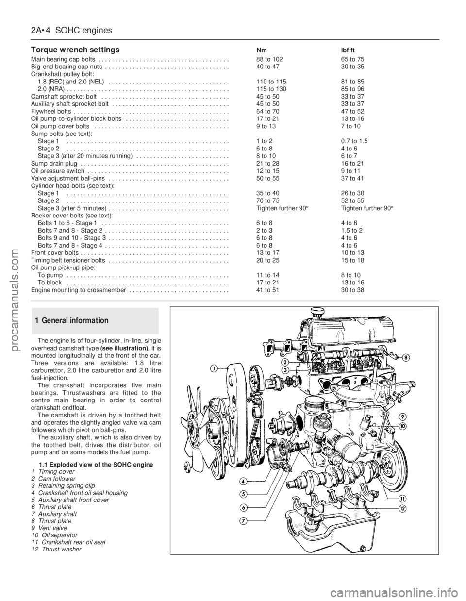
The engine is of four-cylinder, in-line, single
overhead camshaft type (see illustration). It is
mounted longitudinally at the front of the car.
Three versions are available: 1.8 litre
carburettor, 2.0 litre carburettor and 2.0 litre
fuel-injection.
The crankshaft incorporates five main
bearings. Thrustwashers are fitted to the
centre main bearing in order to control
crankshaft endfloat.
The camshaft is driven by a toothed belt
and operates the slightly angled valve via cam
followers which pivot on ball-pins.
The auxiliary shaft, which is also driven by
the toothed belt, drivesthe distributor, oil
pump and on some models the fuel pump.
1General information
2A•4SOHCengines
Torque wrench settingsNmlbf ft
Main bearing cap bolts . . . . . . . . . . . . . . . . . . . . . . . . . . . . . . . . . . . . . .88 to 10265 to 75
Big-end bearing cap nuts . . . . . . . . . . . . . . . . . . . . . . . . . . . . . . . . . . . .40 to 4730 to 35
Crankshaft pulley bolt:
1.8 (REC) and 2.0 (NEL) . . . . . . . . . . . . . . . . . . . . . . . . . . . . . . . . . . .110 to 11581 to 85
2.0 (NRA) . . . . . . . . . . . . . . . . . . . . . . . . . . . . . . . . . . . . . . . . . . . . . . .115 to 13085 to 96
Camshaft sprocket bolt . . . . . . . . . . . . . . . . . . . . . . . . . . . . . . . . . . . . .45 to 5033 to 37
Auxiliary shaft sprocket bolt . . . . . . . . . . . . . . . . . . . . . . . . . . . . . . . . . .45 to 5033 to 37
Flywheel bolts . . . . . . . . . . . . . . . . . . . . . . . . . . . . . . . . . . . . . . . . . . . . .64 to 7047 to 52
Oil pump-to-cylinder block bolts . . . . . . . . . . . . . . . . . . . . . . . . . . . . . .17 to 2113 to 16
Oil pump cover bolts . . . . . . . . . . . . . . . . . . . . . . . . . . . . . . . . . . . . . . .9 to 137 to 10
Sump bolts (see text):
Stage 1 . . . . . . . . . . . . . . . . . . . . . . . . . . . . . . . . . . . . . . . . . . . . . . .1 to 20.7 to 1.5
Stage 2 . . . . . . . . . . . . . . . . . . . . . . . . . . . . . . . . . . . . . . . . . . . . . . .6 to 84 to 6
Stage 3 (after 20 minutes running) . . . . . . . . . . . . . . . . . . . . . . . . . . .8 to 106 to 7
Sump drain plug . . . . . . . . . . . . . . . . . . . . . . . . . . . . . . . . . . . . . . . . . . .21 to 2816 to 21
Oil pressure switch . . . . . . . . . . . . . . . . . . . . . . . . . . . . . . . . . . . . . . . . .12 to 159 to 11
Valve adjustment ball-pins . . . . . . . . . . . . . . . . . . . . . . . . . . . . . . . . . . .50 to 5537 to 41
Cylinder head bolts (see text):
Stage 1 . . . . . . . . . . . . . . . . . . . . . . . . . . . . . . . . . . . . . . . . . . . . . . .35 to 4026 to 30
Stage 2 . . . . . . . . . . . . . . . . . . . . . . . . . . . . . . . . . . . . . . . . . . . . . . .70 to 7552 to 55
Stage 3 (after 5 minutes) . . . . . . . . . . . . . . . . . . . . . . . . . . . . . . . . . . .Tighten further 90°Tighten further 90°
Rocker cover bolts (see text):
Bolts 1 to 6 - Stage 1 . . . . . . . . . . . . . . . . . . . . . . . . . . . . . . . . . . . . .6 to 84 to 6
Bolts 7 and 8 - Stage 2 . . . . . . . . . . . . . . . . . . . . . . . . . . . . . . . . . . . .2 to 31.5 to 2
Bolts 9 and 10 - Stage 3 . . . . . . . . . . . . . . . . . . . . . . . . . . . . . . . . . . .6 to 84 to 6
Bolts 7 and 8 - Stage 4 . . . . . . . . . . . . . . . . . . . . . . . . . . . . . . . . . . . .6 to 84 to 6
Front cover bolts . . . . . . . . . . . . . . . . . . . . . . . . . . . . . . . . . . . . . . . . . . .13 to 1710 to 13
Timing belt tensioner bolts . . . . . . . . . . . . . . . . . . . . . . . . . . . . . . . . . . .20 to 2515 to 18
Oil pump pick-up pipe:
To pump . . . . . . . . . . . . . . . . . . . . . . . . . . . . . . . . . . . . . . . . . . . . . . .11 to 148 to 10
To block . . . . . . . . . . . . . . . . . . . . . . . . . . . . . . . . . . . . . . . . . . . . . . .17 to 2113 to 16
Engine mounting to crossmember . . . . . . . . . . . . . . . . . . . . . . . . . . . . .41 to 5130 to 38
1.1 Exploded view of the SOHC engine
1 Timing cover
2 Cam follower
3 Retaining spring clip
4 Crankshaft front oil seal housing
5 Auxiliary shaft front cover
6 Thrust plate
7 Auxiliary shaft
8 Thrust plate
9 Vent valve
10 Oil separator
11 Crankshaft rear oil seal
12 Thrust washer
procarmanuals.com
Page 28 of 255
The cylinder head is of crossflow design
with the inlet manifold mounted on the left-
hand side and the exhaust manifold mounted
on the right-hand side.
Lubrication is by means of a bi-rotor pump
which draws oil through a strainer located
inside the sump, and forces it through a full-
flow filter into the engine oil galleries where it
is distributed to the crankshaft, camshaft and
auxiliary shaft. The big-end bearings are
supplied with oil via internal drillings in the
crankshaft.The undersides of the pistons are
supplied with oil from drillings in the big-ends.
The distributor shaft is intermittently supplied
with oil from the drilled auxiliary shaft. The
camshaft and cam followers are supplied with
oil via a drilled spray tube from the centre
camshaft bearing.
A semi-closed crankcase ventilation system
is employed whereby piston blow-by gases
are drawn into the inlet manifold via an oil
separator and on carburettor models a control
valve.
The following operations can be carried out
without removing the engine, although the
work may be easier and quicker with the
engine removed:
a)Removal and refitting of the cylinder head
b)Removal and refitting of the camshaft
(after removing the cylinder head)
c)Removal and refitting of the timing belt
and sprockets
d)Removal and refitting of the sump and oil
pump
e)Removal and refitting of the pistons,
connecting rods and big-end bearings
f)Renewal of the engine mountings
g)Renewal of the crankshaft oil seals
h)Removal and refitting of the auxiliary shaft
j)Removal and refitting of the flywheel
The engine must be removed from the
vehicle for the following operations:
a)Renewal of the crankshaft main bearings
b)Removal and refitting of the crankshaft
The engine may be lifted out either on its
own or together with the gearbox. Unless work
is also necessary on the gearbox it is
recommended that the engine is removed on
its own. Where automatic transmission is
fitted, the engine should be removed on its
own owing to the additional weight. If the
engine and gearbox are removed together,
they will have to be tilted at a very steep angle;
make sure that the range of the lifting tackle is
adequate.1Disconnect the battery negative lead.
2Remove the bonnet.
3On carburettor models, remove the air
cleaner. On fuel-injection models, remove the
air cleaner cover, vane airflow meter and air
inlet trunking.
4If a splash guard is fitted, remove it.
5Release the securing clips and bolts and
remove the upper half of the fan shroud. On
carburettor models remove the lower half of
the shroud too.
6Drain the cooling system.
7Disconnect the radiator top and bottom
hoses from the thermostat housing and water
pump. Disconnect the top hose spur from the
expansion tank and unclip it.
8Disconnect the heater hoses from the water
pump and from the inlet manifold or automatic
choke housing. Unclip the hoses.
9On models with power steering, remove the
steering pump.
10Disconnect the vacuum pipe(s) from the
inlet manifold, labelling them if there is any
possibility of confusion.
11Disconnect the following wiring, as
applicable:
a)Alternator
b)Temperature gauge sender
c)Engine management temperature sensor
d)Distributor
e)Oil pressure switch
f)Automatic choke and thermo-switch
g)Carburettor stepper motor
h)Fuel-injection system sub-harness
j)Inlet manifold heater
12Disconnect the HT lead from the coil.
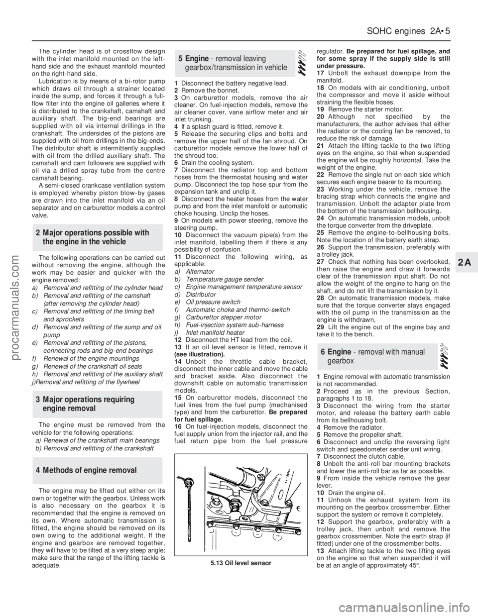
13If an oil level sensor is fitted, remove it
(see illustration).
14Unbolt the throttle cable bracket,
disconnect the inner cable and move the cable
and bracket aside. Also disconnect the
downshift cable on automatic transmission
models.
15On carburettor models, disconnect the
fuel lines from the fuel pump (mechanised
type) and from the carburettor. Be prepared
for fuel spillage.
16On fuel-injection models, disconnect the
fuel supply union from the injector rail, and the
fuel return pipe from the fuel pressureregulator. Be prepared for fuel spillage, and
for some spray if the supply side is still
under pressure.
17Unbolt the exhaust downpipe from the
manifold.
18On models with air conditioning, unbolt
the compressor and move it aside without
straining the flexible hoses.
19Remove the starter motor.
20Although not specified by the
manufacturers, the author advises that either
the radiator or the cooling fan be removed, to
reduce the risk of damage.
21Attach the lifting tackle to the two lifting
eyes on the engine, so that when suspended
the engine will be roughly horizontal. Take the
weight of the engine.
22Remove the single nut on each side which
secures each engine bearer to its mounting.
23Working under the vehicle, remove the
bracing strap which connects the engine and
transmission. Unbolt the adapter plate from
the bottom of the transmission bellhousing.
24On automatic transmission models, unbolt
the torque converter from the driveplate.
25Remove the engine-to-bellhousing bolts.
Note the location of the battery earth strap.
26Support the transmission, preferably with
a trolley jack.
27Check that nothing has been overlooked,
then raise the engine and draw it forwards
clear of the transmission input shaft. Do not
allow the weight of the engine to hang on the
shaft, and do not lift the transmission by it.
28On automatic transmission models, make
sure that the torque converter stays engaged
with the oil pump in the transmission as the
engine is withdrawn,
29Lift the engine out of the engine bay and
take it to the bench.
1Engine removal with automatic transmission
is not recommended.
2Proceed as in the previous Section,
paragraphs 1 to 18.
3Disconnect the wiring from the starter
motor, and release the battery earth cable
from its bellhousing bolt.
4Remove the radiator.
5Remove the propeller shaft.
6Disconnect and unclip the reversing light
switch and speedometer sender unit wiring.
7Disconnect the clutch cable.
8Unbolt the anti-roll bar mounting brackets
and lower the anti-roll bar as far as possible.
9From inside the vehicle remove the gear
lever.
10Drain the engine oil.
11Unhook the exhaust system from its
mounting on the gearbox crossmember. Either
support the system or remove it completely.
12Support the gearbox, preferably with a
trolley jack, then unbolt and remove the
gearbox crossmember. Note the earth strap (if
fitted) under one of the crossmember bolts.
13Attach lifting tackle to the two lifting eyes
on the engine so that when suspended it will
be at an angle of approximately 45°.
6Engine - removal with manual
gearbox
5Engine - removal leaving
gearbox/transmission in vehicle
4Methods of engine removal
3Major operations requiring
engine removal
2Major operations possible with
the engine in the vehicle
SOHCengines 2A•5
2A
5.13 Oil level sensor
procarmanuals.com
Page 29 of 255
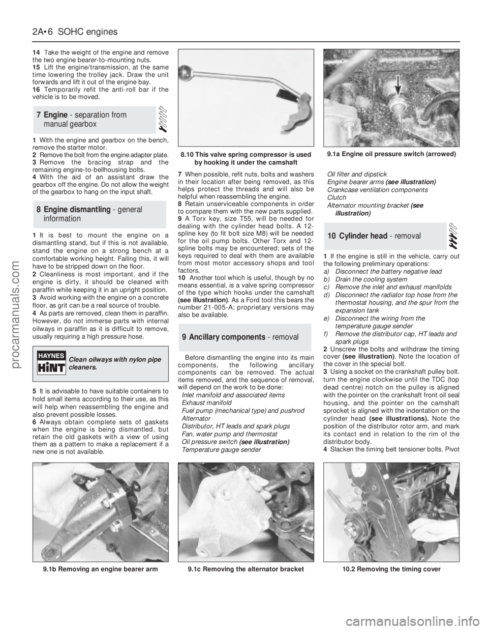
14Take the weight of the engine and remove
the two engine bearer-to-mounting nuts.
15Lift the engine/transmission, at the same
time lowering the trolley jack. Draw the unit
forwards and lift it out of the engine bay.
16Temporarily refit the anti-roll bar if the
vehicle is to be moved.
1With the engine and gearbox on the bench,
remove the starter motor.
2Remove the bolt from the engine adapter plate.
3Remove the bracing strap and the
remaining engine-to-bellhousing bolts.
4With the aid of an assistant draw the
gearbox off the engine. Do not allow the weight
of the gearbox to hang on the input shaft.
1It is best to mount the engine on a
dismantling stand, but if this is not available,
stand the engine on a strong bench at a
comfortable working height. Failing this, it will
have to be stripped down on the floor.
2Cleanliness is most important, and if the
engine is dirty, it should be cleaned with
paraffin while keeping it in an upright position.
3Avoid working with the engine on a concrete
floor, as grit can be a real source of trouble.
4As parts are removed, clean them in paraffin.
However, do not immerse parts with internal
oilways in paraffin as it is difficult to remove,
usually requiring a high pressure hose.
5It is advisable to have suitable containers to
hold small items according to their use, as this
will help when reassembling the engine and
also prevent possible losses.
6Always obtain complete sets of gaskets
when the engine is being dismantled, but
retain the old gaskets with a view of using
them as a pattern to make a replacement if a
new one is not available.7When possible, refit nuts, bolts and washers
in their location after being removed, as this
helps protect the threads and will also be
helpful when reassembling the engine.
8Retain unserviceable components in order
to compare them with the new parts supplied.
9A Torx key, size T55, will be needed for
dealing with the cylinder head bolts. A 12-
spline key (to fit bolt size M8) will be needed
for the oil pump bolts. Other Torx and 12-
spline bolts may be encountered; sets of the
keys required to deal with them are available
from most motor accessory shops and tool
factors.
10Another tool which is useful, though by no
means essential, is a valve spring compressor
of the type which hooks under the camshaft
(see illustration). As a Ford tool this bears the
number 21-005-A; proprietary versions may
also be available.
Before dismantling the engine into its main
components, the following ancillary
components can be removed. The actual
items removed, and the sequence of removal,
will depend on the work to be done:
Inlet manifold and associated items
Exhaust manifold
Fuel pump (mechanical type) and pushrod
Alternator
Distributor, HT leads and spark plugs
Fan, water pump and thermostat
Oil pressure switch
(see illustration)
Temperature gauge senderOil filter and dipstick
Engine bearer arms (see illustration)
Crankcase ventilation components
Clutch
Alternator mounting bracket (see
illustration)
1If the engine is still in the vehicle, carry out
the following preliminary operations:
a)Disconnect the battery negative lead
b)Drain the cooling system
c)Remove the inlet and exhaust manifolds
d)Disconnect the radiator top hose from the
thermostat housing, and the spur from the
expansion tank
e)Disconnect the wiring from the
temperature gauge sender
f)Remove the distributor cap, HT leads and
spark plugs
2Unscrew the bolts and withdraw the timing
cover (see illustration). Note the location of
the cover in the special bolt.
3Using a socket on the crankshaft pulley bolt.
turn the engine clockwise until the TDC (top
dead centre) notch on the pulley is aligned
with the pointer on the crankshaft front oil seal
housing, and the pointer on the camshaft
sprocket is aligned with the indentation on the
cylinder head (see illustrations).Note the
position of the distributor rotor arm, and mark
its contact end in relation to the rim of the
distributor body.
4Slacken the timing belt tensioner bolts. Pivot
10Cylinder head - removal
9Ancillary components - removal
8Engine dismantling - general
information
7Engine - separation from
manual gearbox
2A•6SOHCengines
9.1a Engine oil pressure switch (arrowed)
9.1b Removing an engine bearer arm9.1c Removing the alternator bracket
8.10 This valve spring compressor is used
by hooking it under the camshaft
Clean oilways with nylon pipe
cleaners.
10.2 Removing the timing cover
procarmanuals.com
Page 30 of 255
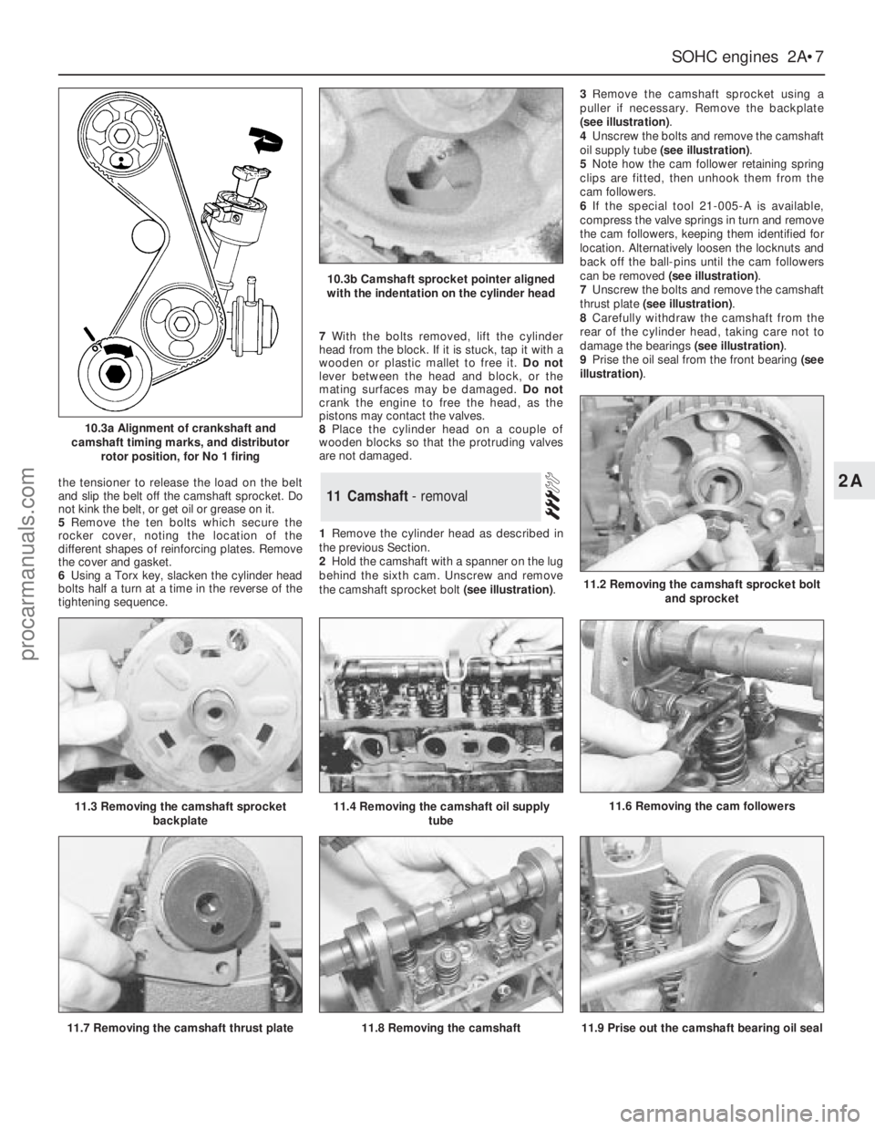
the tensioner to release the load on the belt
and slip the belt off the camshaft sprocket. Do
not kink the belt, or get oil or grease on it.
5Remove the ten bolts which secure the
rocker cover, noting the location of the
different shapes of reinforcing plates. Remove
the cover and gasket.
6Using a Torx key, slacken the cylinder head
bolts half a turn at a time in the reverse of the
tightening sequence.7With the bolts removed, lift the cylinder
head from the block. If it is stuck, tap it with a
wooden or plastic mallet to free it. Do not
lever between the head and block, or the
mating surfaces may be damaged. Do not
crank the engine to free the head, as the
pistons may contact the valves.
8Place the cylinder head on a couple of
wooden blocks so that the protruding valves
are not damaged.
1Remove the cylinder head as described in
the previous Section.
2Hold the camshaft with a spanner on the lug
behind the sixth cam. Unscrew and remove
the camshaft sprocket bolt (see illustration).3Remove the camshaft sprocket using a
puller if necessary. Remove the backplate
(see illustration).
4Unscrew the bolts and remove the camshaft
oil supply tube (see illustration).
5Note how the cam follower retaining spring
clips are fitted, then unhook them from the
cam followers.
6If the special tool 21-005-A is available,
compress the valve springs in turn and remove
the cam followers, keeping them identified for
location. Alternatively loosen the locknuts and
back off the ball-pins until the cam followers
can be removed (see illustration).
7Unscrew the bolts and remove the camshaft
thrust plate (see illustration).
8Carefully withdraw the camshaft from the
rear of the cylinder head, taking care not to
damage the bearings (see illustration).
9Prise the oil seal from the front bearing (see
illustration).11Camshaft - removal
SOHCengines 2A•7
2A
10.3a Alignment of crankshaft and
camshaft timing marks, and distributor
rotor position, for No 1 firing
10.3b Camshaft sprocket pointer aligned
with the indentation on the cylinder head
11.6 Removing the cam followers
11.2 Removing the camshaft sprocket bolt
and sprocket
11.3 Removing the camshaft sprocket
backplate11.4 Removing the camshaft oil supply
tube
11.9 Prise out the camshaft bearing oil seal11.7 Removing the camshaft thrust plate11.8 Removing the camshaft
procarmanuals.com
Page 31 of 255
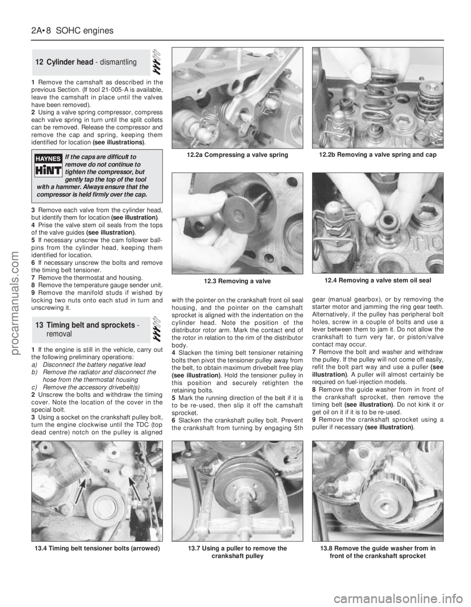
1Remove the camshaft as described in the
previous Section. (If tool 21-005-A is available,
leave the camshaft in place until the valves
have been removed).
2Using a valve spring compressor, compress
each valve spring in turn until the split collets
can be removed. Release the compressor and
remove the cap and spring, keeping them
identified for location (see illustrations).
3Remove each valve from the cylinder head,
but identify them for location (see illustration).
4Prise the valve stem oil seals from the tops
of the valve guides (see illustration).
5If necessary unscrew the cam follower ball-
pins from the cylinder head, keeping them
identified for location.
6If necessary unscrew the bolts and remove
the timing belt tensioner.
7Remove the thermostat and housing.
8Remove the temperature gauge sender unit.
9Remove the manifold studs if wished by
locking two nuts onto each stud in turn and
unscrewing it.
1If the engine is still in the vehicle, carry out
the following preliminary operations:
a)Disconnect the battery negative lead
b)Remove the radiator and disconnect the
hose from the thermostat housing
c)Remove the accessory drivebelt(s)
2Unscrew the bolts and withdraw the timing
cover. Note the location of the cover in the
special bolt.
3Using a socket on the crankshaft pulley bolt,
turn the engine clockwise until the TDC (top
dead centre) notch on the pulley is alignedwith the pointer on the crankshaft front oil seal
housing, and the pointer on the camshaft
sprocket is aligned with the indentation on the
cylinder head. Note the position of the
distributor rotor arm. Mark the contact end of
the rotor in relation to the rim of the distributor
body.
4Slacken the timing belt tensioner retaining
bolts then pivot the tensioner pulley away from
the belt, to obtain maximum drivebelt free play
(see illustration). Hold the tensioner pulley in
this position and securely retighten the
retaining bolts.
5Mark the running direction of the belt if it is
to be re-used, then slip it off the camshaft
sprocket.
6Slacken the crankshaft pulley bolt. Prevent
the crankshaft from turning by engaging 5thgear (manual gearbox), or by removing the
starter motor and jamming the ring gear teeth.
Alternatively, if the pulley has peripheral bolt
holes, screw in a couple of bolts and use a
lever between them to jam it. Do not allow the
crankshaft to turn very far, or piston/valve
contact may occur.
7Remove the bolt and washer and withdraw
the pulley. If the pulley will not come off easily,
refit the bolt part way and use a puller (see
illustration). A puller will almost certainly be
required on fuel-injection models.
8Remove the guide washer from in front of
the crankshaft sprocket, then remove the
timing belt (see illustration). Do not kink it or
get oil on it if it is to be re-used.
9Remove the crankshaft sprocket using a
puller if necessary (see illustration).
13Timing belt and sprockets -
removal
12Cylinder head - dismantling
2A•8SOHCengines
12.2a Compressing a valve spring
13.4 Timing belt tensioner bolts (arrowed)13.7 Using a puller to remove the
crankshaft pulley
12.4 Removing a valve stem oil seal
13.8 Remove the guide washer from in
front of the crankshaft sprocket
12.2b Removing a valve spring and cap
12.3 Removing a valve
If the caps are difficult to
remove do not continue to
tighten the compressor, but
gently tap the top of the tool
with a hammer. Always ensure that the
compressor is held firmly over the cap.
procarmanuals.com
Page 32 of 255
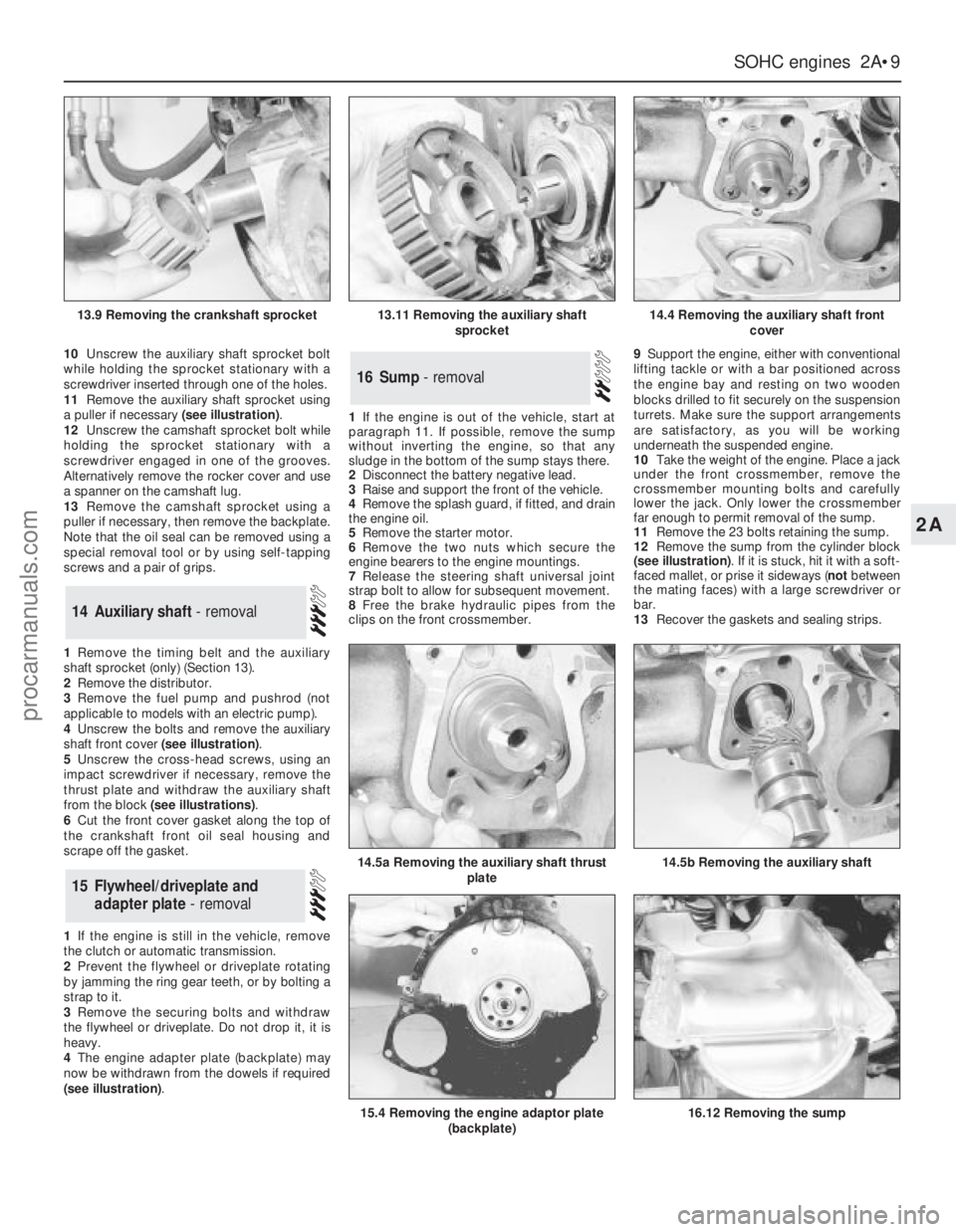
10Unscrew the auxiliary shaft sprocket bolt
while holding the sprocket stationary with a
screwdriver inserted through one of the holes.
11Remove the auxiliary shaft sprocket using
a puller if necessary (see illustration).
12Unscrew the camshaft sprocket bolt while
holding the sprocket stationary with a
screwdriver engaged in one of the grooves.
Alternatively remove the rocker cover and use
a spanner on the camshaft lug.
13Remove the camshaft sprocket using a
puller if necessary, then remove the backplate.
Note that the oil seal can be removed using a
special removal tool or by using self-tapping
screws and a pair of grips.
1Remove the timing belt and the auxiliary
shaft sprocket (only) (Section 13).
2Remove the distributor.
3Remove the fuel pump and pushrod (not
applicable to models with an electric pump).
4Unscrew the bolts and remove the auxiliary
shaft front cover (see illustration).
5Unscrew the cross-head screws, using an
impact screwdriver if necessary, remove the
thrust plate and withdraw the auxiliary shaft
from the block (see illustrations).
6Cut the front cover gasket along the top of
the crankshaft front oil seal housing and
scrape off the gasket.
1If the engine is still in the vehicle, remove
the clutch or automatic transmission.
2Prevent the flywheel or driveplate rotating
by jamming the ring gear teeth, or by bolting a
strap to it.
3Remove the securing bolts and withdraw
the flywheel or driveplate. Do not drop it, it is
heavy.
4The engine adapter plate (backplate) may
now be withdrawn from the dowels if required
(see illustration).1If the engine is out of the vehicle, start at
paragraph 11. If possible, remove the sump
without inverting the engine, so that any
sludge in the bottom of the sump stays there.
2Disconnect the battery negative lead.
3Raise and support the front of the vehicle.
4Remove the splash guard, if fitted, and drain
the engine oil.
5Remove the starter motor.
6Remove the two nuts which secure the
engine bearers to the engine mountings.
7Release the steering shaft universal joint
strap bolt to allow for subsequent movement.
8Free the brake hydraulic pipes from the
clips on the front crossmember.9Support the engine, either with conventional
lifting tackle or with a bar positioned across
the engine bay and resting on two wooden
blocks drilled to fit securely on the suspension
turrets. Make sure the support arrangements
are satisfactory, as you will be working
underneath the suspended engine.
10Take the weight of the engine. Place a jack
under the front crossmember, remove the
crossmember mounting bolts and carefully
lower the jack. Only lower the crossmember
far enough to permit removal of the sump.
11Remove the 23 bolts retaining the sump.
12Remove the sump from the cylinder block
(see illustration). If it is stuck, hit it with a soft-
faced mallet, or prise it sideways (notbetween
the mating faces) with a large screwdriver or
bar.
13Recover the gaskets and sealing strips.
16Sump - removal
15Flywheel/driveplate and
adapter plate - removal
14Auxiliary shaft - removal
SOHCengines 2A•9
2A
13.9 Removing the crankshaft sprocket13.11 Removing the auxiliary shaft
sprocket14.4 Removing the auxiliary shaft front
cover
14.5b Removing the auxiliary shaft14.5a Removing the auxiliary shaft thrust
plate
15.4 Removing the engine adaptor plate
(backplate)16.12 Removing the sump
procarmanuals.com
 1
1 2
2 3
3 4
4 5
5 6
6 7
7 8
8 9
9 10
10 11
11 12
12 13
13 14
14 15
15 16
16 17
17 18
18 19
19 20
20 21
21 22
22 23
23 24
24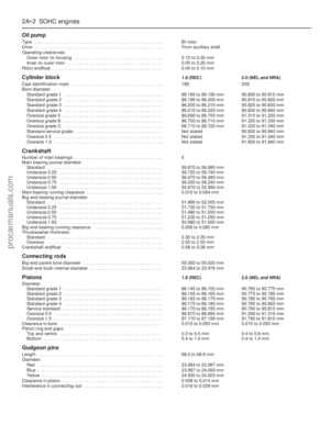 25
25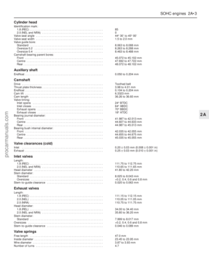 26
26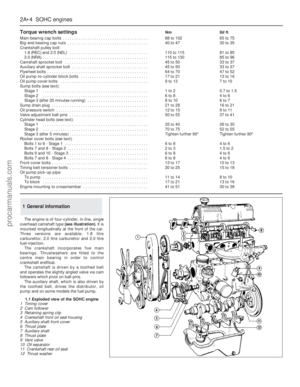 27
27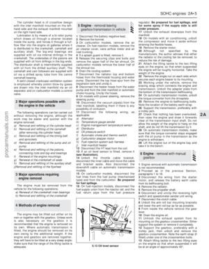 28
28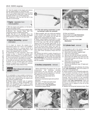 29
29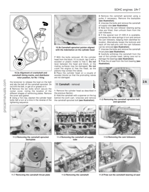 30
30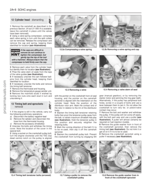 31
31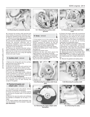 32
32 33
33 34
34 35
35 36
36 37
37 38
38 39
39 40
40 41
41 42
42 43
43 44
44 45
45 46
46 47
47 48
48 49
49 50
50 51
51 52
52 53
53 54
54 55
55 56
56 57
57 58
58 59
59 60
60 61
61 62
62 63
63 64
64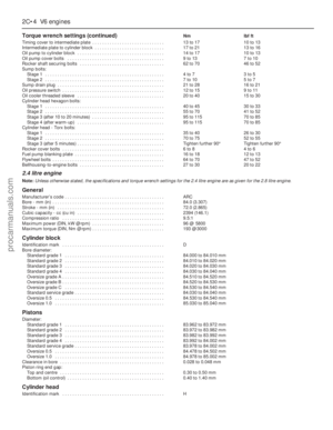 65
65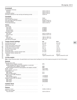 66
66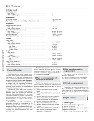 67
67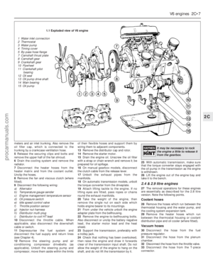 68
68 69
69 70
70 71
71 72
72 73
73 74
74 75
75 76
76 77
77 78
78 79
79 80
80 81
81 82
82 83
83 84
84 85
85 86
86 87
87 88
88 89
89 90
90 91
91 92
92 93
93 94
94 95
95 96
96 97
97 98
98 99
99 100
100 101
101 102
102 103
103 104
104 105
105 106
106 107
107 108
108 109
109 110
110 111
111 112
112 113
113 114
114 115
115 116
116 117
117 118
118 119
119 120
120 121
121 122
122 123
123 124
124 125
125 126
126 127
127 128
128 129
129 130
130 131
131 132
132 133
133 134
134 135
135 136
136 137
137 138
138 139
139 140
140 141
141 142
142 143
143 144
144 145
145 146
146 147
147 148
148 149
149 150
150 151
151 152
152 153
153 154
154 155
155 156
156 157
157 158
158 159
159 160
160 161
161 162
162 163
163 164
164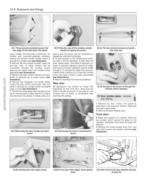 165
165 166
166 167
167 168
168 169
169 170
170 171
171 172
172 173
173 174
174 175
175 176
176 177
177 178
178 179
179 180
180 181
181 182
182 183
183 184
184 185
185 186
186 187
187 188
188 189
189 190
190 191
191 192
192 193
193 194
194 195
195 196
196 197
197 198
198 199
199 200
200 201
201 202
202 203
203 204
204 205
205 206
206 207
207 208
208 209
209 210
210 211
211 212
212 213
213 214
214 215
215 216
216 217
217 218
218 219
219 220
220 221
221 222
222 223
223 224
224 225
225 226
226 227
227 228
228 229
229 230
230 231
231 232
232 233
233 234
234 235
235 236
236 237
237 238
238 239
239 240
240 241
241 242
242 243
243 244
244 245
245 246
246 247
247 248
248 249
249 250
250 251
251 252
252 253
253 254
254


