Page 361 of 425
CD Player and Air Conditioning System-8
Step 6: Display “06”(set the temperature zone)
Press down “Temp+” switch
Display the detection code of mode/
temperature damper executor
Press down “Te mp+” switch
Step 7: display
“07”(set the temperature zone)
Action of the executor mechanism
:
M ode damper: wind to the person
Circulation damper: internal circulation
Te mperature damper: cold end
Wind amount: the maximum
Compressor: enabled Note: X is a digital number without specific meaning; the code
number
is displayed in the outside temperature display zone.
d isplay
“08”
C
Code number Code Meaning
0x0 Temperature damper executor works normally
0x1 Detection for temperature damper executor is in progress.
0x2 Temperature damper executor failure
00x Mode damper executor works normally
01x Detection for mode damper executor is in progress.
02x Mode damper executor failure
Page 362 of 425
CD Player and Air Conditioning System-9
Step 9: display “09”
Action of the executor mechanism:
Mode damper: wind to the person and the fee
Circulation damper: internal circulation
Temperature damper: in the middle
W ind amount: bigger
Compressor: enabled
Action of the executor mechanism
:
M ode damper: wind to the feet and defrost
Circulation damper: external circulation
Te
m perature damper: in the middle Wind amount: small
Compressor: off
display
“
10”(set the temperature zone)
Action of the executor mechanism
:
M
ode damper: wind to the person and the feet
Circulation damper: external circulation
Te mperature damper: hot end
Wind amount: medium
Compressor: enabled
Press down
“Temp+” switch
Press
down
“Temp+” switch
Page 363 of 425

CD Player and Air Conditioning System-10
Refrigeration of air conditioner failed
T rou ble Des crip tion s Ana l ysis o f the Cause
1.No pick -up o f com pressor 1.
fuse burned down , com presso r’s r elay dama ge
d
2. pressu re sw itch contac t d isco nn ected, short c ircu itor open circ uit o f the
ro utin
g
3. open circ ui t o f clutch’ s w indi ng
4. sw itch burned down
5. ma ster relay b urne d d ow
n
6.
s lid e o f the clut ch
7. beltof the c om presso r b roke ortoo l oose
8. comp ressor failur
e
9. sens or failur e(ju dg ed by read ing t he failu recode
)
10. insu ffic ient cold me dia, lowe r system p ress ur e(< 0 .97M Pa
)
11. system pressu re abov e 1 .37M Pa
12. water t em peratu re of the e ngine t oo high
13. V oltag e o f the clut ch below 7
V
2. Pick -up o f Com pressor 1.
norm
ally -ope n c ontact of the c om presso r’s r elay stuc k a nd seriou s leaka ge
of system cold me dia, system runn ing s hortof cold me di
a
2. no wind from the b lowe
r
R e frig eratio n of
ai r c ondition in
g
syst emfaile
d
3.no wind from the b lowe
r 1.
fuse burned down
2. mo tor b rush ofthe b lowe r dam aged
3. sw itch ofthe b lowe r dam aged
4. comi ng off o f d istrib utio n w ire c onnector s o r circu itdisc
onne cted
5. speed-ad justin g m odule d amaged
6. no wind from the b lowe r w hen a t high s peed, h igh- sp ee d r elay dama ge
d
Press down “Temp+” switch
Step 11: display “11”(set the temperature zone)
Action of the executor mechanism
:
M ode damper: defrost
Circulation damper: external circulation
Te mperature damper: cold end
Wind amount: the minimum
Compressor: off
Attention: during the inspection period fr om step 7 to step 11, the controlle r
will for cibly transit the output signal based on
the code number displayed on the integrated display screen to the functioned executor; the inspection must be done with
such
m ethods as visual inspection, listening to abnormal sound or touching the air vent by hand so as to judge whether
there is any improper operation.
T rouble Diagnosis and T roubleshooting of A i r Conditioning System
Air cooling system
Page 364 of 425

CD Player and Air Conditioning System-11
b .Insufficient refrigeration output
T rou ble D escrip tion s Ana l ysis o f the Cause
I nad equate
re fri g eratio
n 1.
wind amount
is no rm al 1.
comp ress or wo rks n orma ll
y
(1 ) low- leve l p ressu reathigh -pressu reand l ow -pressu reside
s
a. bloc k o f exp ansion valv
e
b. op enness of expa nsion v alve too n arro
w
(2 ) h igh- leve l p ressu reathigh -pressu reand l ow -pressu reside
s
a. failur e t o h igh- vo ltag e p ip
elin e,flow not smooth
b. ma lfun ctio n o f the rm o resisto
r
c. op
enne ssof expa nsion v alve too w ide
d. too m uch r efrige ration oi
l
e. too m uch r efrige rant
f. po or heat diss ipatio n o f the cond ense
r
(3 ) p ress ure a t high- vo ltag e s ide t oo lo
w
a. low- pr
essu repipe line dama ged
b. bloc k o f low -pressu repipe lin
e
(4 )pressu reatlow- pr
essu reside too l ow
a. the e vapo rato r f rosted
b. bloc k o f expansion valv
e
c. low- pr
essu repipe line not smo oth
d. ma lfun ctio n o f the rm o resisto
r
(5 )pressu re at low- pr
essu re side some time norm al, s ometim es with negative pressu re,
mo istu re and i ce bloc k i n a irco oling s yste
m
(6 )neg ative p ress ur e a t low -pressu reside , p ressu reathigh -pressu reside too l ow , block ofai
r
co oling s yste
m
(7 )pressu reatlow- pr
essu reside too l ow , pressu reathigh -pressu reside too h i gh
a. intern al bloc k o f drier of f lui d r eservo ir
b. bloc k o f high- pr essu re pipe lin
e
(8 )pressu reatlow- pr
essu reside too h igh, pressu re athigh -press ure s ide t oo low
a. leak ag e o f the comp resso
r
b. dama ged v alve ofcomp resso
r
(9 )poo r h eat r ad iation ofcond enser d ue tosm all w ind a mo unt from t hecond ensing blow er
2. comp ress or wo rks i mp rope rl
y
(1 )int erna l m alfu nc tion ofcomp ress or
(2 )belt o f com pr
esso r too loos e o r slidi ng
(3 )fai lu re of elec trom agnetic c lutc
h
a. low vol tage ofpowe r suppl
y
b. mu tual interfer en ce ofthe s tato r and roto
r
c. ma lfun ctio n o f amp lifier s tabi lizi ng the i dle s peed
d. circ uit d isco nn ected, comi ng off o f the joi n ts
e. po or operatio n o f the sw itch and r elay
f. sh ort c ircu itan d o pen c ircu itof the r outing
g. po or earthi ng
3. othe r c ause
s
ba d s ealin g o f w agon
Page 365 of 425

CD Player and Air Conditioning System-12
e .Precautions for the overhaul of air cooling system
When the air cooling system encounters the trouble, the cause for such trouble shall be analyzed inlightof trouble varieties,
followed with the examination and report work.
c. T he c ooling system some time s w orks wh ile some time s refus es towo rk.
T rou ble Des cri p tion s Ana l ysis o f the C ause
1.comp ress or wo rks n orma l l y 1.
ice b lock i nthe c ool i ng s yste
m
2. failu reof therma l resisto r o r tem perature sens ing b ul
b
3. poor contac t o f A /Cswitch
4. cond ensing blow erdama ge
d
T he c ooling system
so me time s p rodu ce
s
re f ri g eratio n e f f ect whil
e
so me time s not
.
comp resso r w orks i mprop erl y 1.s
lid e o f the clut ch
2. comi ng off o f the clut ch ’ s wind i n
g
3. poor earthi ng ofclut ch ’ s wind i n
g
d. N oise o f the air c oolin g s ystem
T r ou ble Des cription s Ana l ysis o f the C ause
No ise o f the air c ooling system too
lo ud N o
ise t oo l oud (1
) b elt t oo
loos e or w orn t oo mu ch
(2 ) f asteni ng screw o f mounting h olde r o f the comp resso
r
lo os en ed
(3 ) m ounti n g h olde r o f the comp resso r dam aged
(4 ) i nter na l p arts of the c om pr
esso r dam aged
(5 ) t oo mu chref ri g eratio n o ilor none
(6 ) .
slid e o f the clut ch
(7 ) . B e aring o f the clut ch runni ngshort o f o i lor dama ge
d
(8 ) . mo tor b earing ofthe b lowe r dam aged
(9 ) h olde r o f the blow erbrok en or
loos ened
(1 0) blad e o f the blow erbrok en or
loos ened
(1 1) . F rict io n o f the blow er’ s blad e w ith o ther comp onents
Page 366 of 425

CD Player and Air Conditioning System-13
1 .CC6460K air conditioning system is designed with SD7V16 compressor, whose refrigeration oil type as
specified is SP-10P AG; hence application of other type of refrigeration oil may damage the parts and compo
nents of the compressor. When the
air conditioning system goes through maintenance and replacement of
parts, it should be added with new refrigeration oil, whose volume is listed as follows: the evaporator and
condenser: 30ml; the drier: 20ml; the pipeline: 10ml.
Addition of refrigeration oil can be available with two methods: The direct addition and the vacuum suction
2 .D irect addition method
a. remove the oil filler plug and fill with the specified SP-10P AG refrigeration oil.
b. observe through the hole of oil filter plug and rotate front plate of clutch to make the piston connecting rod right positio n in the
center of the hole of oil filter plug.
c. insert the dipstick along the right side of piston connecting rod till the top of dipstick touches the case of the compresso
r
d. pull out the dipstick and examine the graduations (grooves) of refrigeration oil, the readings shall be within the range of 4-6
scales
.
e. screw firmly the oil filter plug with the fastening torque of 14.7± 4.9N
.m
3. Vacuum suction method:
Firstly pump out the refrigerating system to the vacuum of 0.2x10⁵Pa, and then fill with the specified 0.2x10 5 Pa refrigeration oil;
the detailed steps are as follows:
a. switch off the high-pressure manual valve and the auxiliary valve.
b. dismantle the high-pressure side hose from the manifold pressure gauge and insert it into the oil cu
p
c. open the auxiliary valve and have the refrigeration oil sucked into the refrigerating system from the oil cup.
d. when the refrigeration oil in the oil cup is almost pumped out to the vacuum, then immediately turn off the auxiliary valve
to
prevent the air from being sucked into the system
.
e. secure the hose adapter at high-pressure side to the manifold pressure gauge, start the vacuum pump and turn on the high-
pressure manual valve, then turn on the auxiliary valve to pump the system to the vacuum state of 0.2x10
5Pa, keep such state
for 15mins so as to discharge out the air flowing into the system along with the oil.
V ol ume of Refrigeration Oil Addition and its Methods
2.ai r h eating system
T r oubl e Cau ses o f the trouble
H e ati n g n otsuppl i ed or
no t s
uf f i cientl y suppl i ed 1.
blow erof air c ondition erf ai l u re 2.relay o f the blow erdamage
d
3. heati n g w ater pipe bloc k e d 4 . coo ling water p i pe b lock ed
5. col d/h ot damp erexecutor damage d 6. ins
uf f i cien t c oo ling l iqu id
N o rotation ofblow er 1.
f use burned
down orpoor contac t o f the switch
2. mo tor o f the blowe r burne d d ow
n
3. op en circ uit o f h igh- sp eed relay o f the blow er
4. speed-ad j usti n g m odule d am aged
5. short c ircu it
leak age o f w ater W ater p ipe o f ai rhe ati n g a ged, inse cu re j oi nt
O v erhe at 1.
speed-ad j usti n g r esi sto r o f the f an d am aged
2. col d/h ot damp erexecutor damaged
I nsu f f i cien t h otair
vo lume f or d efro stin
g 1.
mode executor dama ge
d
2. f al li n g o f fof the d riv e ro
d
3. damp ernot in p osi ti o
n
4. air v ent b l ock ed
5. inad equa te heatin g s
upply
6. inst
alla tion ofwind tunn elno t fi t
7. circ uit d i sco nn ecte
d
Page 367 of 425

CD Player and Air Conditioning System-14
Pumping Out of A i r Conditioning System to the Vacuum and Addition of Refrigeration Oil
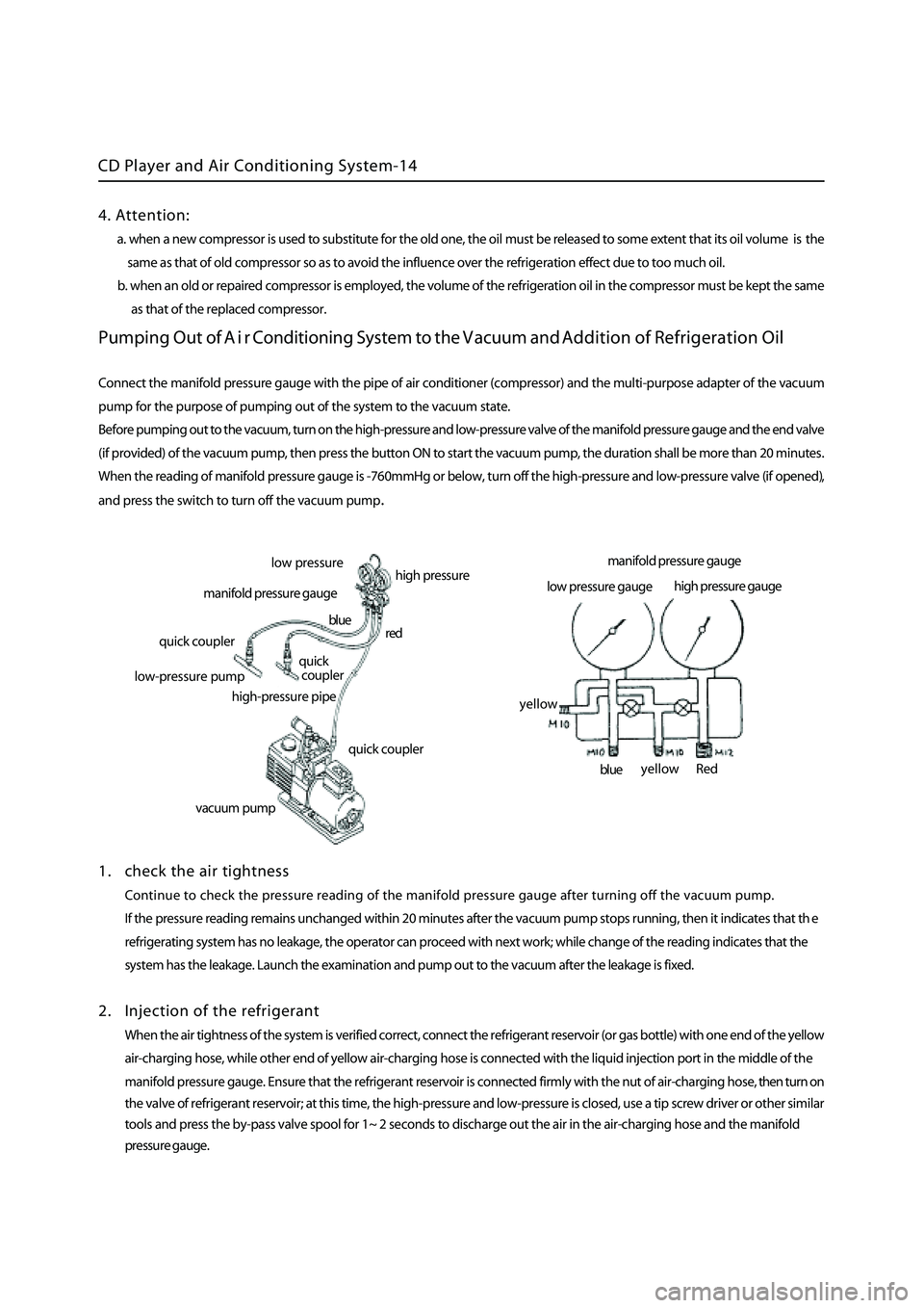
Connect the manifold pressure gauge with the pipe of air conditioner (compressor) and the multi-purpose adapter of the vacuum
pump for the purpose of pumping out of the system to the vacuum state.
Before pumping out to the vacuum, turn on the high-pressure and low-pressure valve of the
manifold pressure gauge and the end valve
(if provided) of the vacuum pump, then press the button ON to start the vacuum pump, the duration shall be more than 20 minutes
.
When the reading of manifold pressure gauge is -760mmHg or below, turn off the high-pressure and low-pressure valve (if opened)
,
and press the switch to turn off the vacuum pum
p.
1 . check the air tightness
Continue to check the pressure reading of the manifold pressure gauge after turning off the vacuum pump.
If the pressure reading remains unchanged within 20 minutes after the vacuum pump stops running, then it indicates that th
e
refrigerating system has no leakage, the operator can proceed with next work; while change of the reading indicates that the
system has the leakage. Launch the examination and pump out to the vacuum after the leakage is fixed.
2 . Injection of the refrigerant
When the air tightness of the system is verified correct, connect the refrigerant reservoir (or gas bottle) with one end of the yellow
a ir-charging hose, while other end of yellow air-charging hose is connected with the liquid injection port in the middle of the
manifold pressure gauge. Ensure that the refrigerant reservoir is connected firmly with the nut of air-charging hose, then turn on
the valve of refrigerant reservoir; at this time, the high-pressure and low-pressure is closed, use a tip screw driver or other
similar
tools and press the by-pass valve spool for 1~ 2 seconds to discharge out the air in the air-charging hose and the manifold
pressure gauge.
low p ressure
high pressure
manifold pressure gauge
quick coupler
l ow-pressure pump
high-pressure pipe
quick coupler
quick
coupler
red
blue
vacuum pum
p
manifold pressure gauge
low pressure gauge high
pressure gauge
Red
blue
yellow
yellow
4. Attention:
a. when a new compressor is used to substitute for the old one, the oil must be released to some extent that its oil volume is the
same as that of old compressor so as to avoid the influence over the refrigeration effect due to too much oil.
b. when an old or repaired compressor is employed, the volume of the refrigeration oil in the compressor must be kept the sam
e
as that of the replaced
compressor.
Page 368 of 425

CD Player and Air Conditioning System-15
Turn on the high-pressure valve on the manifold pressure gauge and inject the refrigerant to the system from high-pressure pipeline.
At this time, the attention shall be given to the readings of high-pressure meter and low-pressure meter, and make sure that these two
pressure all go up. If the refrigerant is being injected while the pressure does not go up, then the joints of the pipeline may be loosened
or the seals damaged, inject the refrigerant once more after finding out the cause and the fixing. When the increase of pressure stops,
turn off the high-pressure valve of the manifold pressure gauge and then start the engine
.
Operate the switch in a way as follows:
Turn the switch of air conditioner to “ON”
Regulate the temperature controller to the coolest position,
Enable the air conveying to the maximum,
Select the internal air circulation between the internal/external air circulation,
During this process, the door and windows will be all opened.
Adjust the engine’s speed to the specified free running speed.
Erect the refrigerant reservoir or gas bottle (have the refrigerant injected into the refrigerating system in a gas state), turn on the
low-pressure valve of the manifold pressure gauge.
When the compressor is at work, please do not turn on the high-pressure valve.
Before checking the refrigeration level, please confirm the injection volume of the refrigerant specified for air conditioning system.
When injecting the refrigerant, carefully observe the high-pressure side of the manifold pressure gauge and the flow condition of
the refrigerant (clear, foaming or turbid), all these could be viewed through the inspection window, by which the moment of stop
injecting the refrigerant can be reasonably judged(turning off the low-pressure valve).
air washingoff
off
tip screw driverred
yellow blue
refrigerant reservoirhigh-pressure low-pressure
off
low-pressure pipe
high-pressure pipe
refrigerant reservoiryellowred blueon