Page 9 of 425
Preface
Table of Contents
Instruction How to use the manual
Chapter 1 Overview of the entire car (parameters)
Chapter 2 Fuel supply system and exhaust air system
Chapter 3 Clutch
Chapter 4 Transmission
Chapter 5 Automatic transmission
Chapter 6 Driving shaft
Chapter 7 Suspension and vehicle axle
Chapter 8 Brake (ABS)
Chapter 9 Steering
Chapter 10 Car body electric appliance
Chapter 11 CD player and air-conditioning system
Chapter 12 Safety airbag
Annex:
Important components guarantee and requirement
List of non-metal material consumption
Special tools
D Important working components and tightening torque
E Electric wiring diagram
Page 10 of 425

Overview of the entire car-1
Chapter 1
Overview of the entire car
Basic parameter....................................................... 2
Engine..................................................................... 4
Air inlet system........................................................ 5
Exhaust air system................................................... 5
Fuel supply system................................................... 5
Cooling system........................................................ 5
Clutch..................................................................... 5
Transmission............................................................ 6
Drive shaft............................................................... 6
Front shaft/axle........................................................ 6
Rear axle................................................................. 6
Wheel tyre............................................................... 6
Suspension.............................................................. 7
Frame..................................................................... 7
Steering system........................................................ 7
Brake system........................................................... 8
Car body................................................................. 9
Electrical system.................................................... 10
Air-conditioning system …………………..............12
Page 11 of 425

Basic parameter
The basic parameters of the complete vehicle of CC6460K and CC6460KY estate car should be in accordance with the regulation
in Table 1.
Basic parameters of the complete vehicle of CC6460K and CC6460KY
Item CC6460K CC6460KY
Dimension parameter(no-load)(mm)
L 4620
W 1800
H 1710(car
body)/1755(with
tail fin and
luggage carrier) 1700(car body)/1765(with tail fin
and luggage carrier)
Axle tread 2700
Wheel tread: front/rear 1515/1520
Front suspension 850
Rear suspension 1070
weight parameter:
Loading weight(kg) 5 person × 65kg/person + 150kg
Complete weight(kg) 1720 1830
Max. total weight(kg) 2195 2305
No-load axial load distribution: front/rear(kg) 890/830 980/850
full-load axial load distribution: front/rear(kg) 980/1215 1070/1235
Traffic ability parameter
Min. turning diameter(m) ≤13
Min. ground clearance (mm) ≥180 ≥175
Approach angle(°) ≥28(no-load)
departure angle(°) ≥27.5(no-load)
Dynamic parameter:
Min. stable speed of direct step(km/h) ≤25
30km/h~100km/h acceleration time of direct step(s) ≤32
acceleration time from 1 step starting to 100km/h(s) ≤20
Max. speed(km/h) ≥160
Max. Climbing capability(%) ≥35
Economical character:
Slipping distance in initial speed of 50km/h(m) ≥500
Traveling fuel consumption in 90km/h constant speed (L/100km) ≤10.19
Traveling fuel consumption in 120km/h constant speed (L/100km) ≤13.24
Under simulated urban and suburb comprehensive operating
condition(L/100km) ≤11.9 ≤12.5
Braking characteristics:
Traveling braking distance in 50km/h braking initial speed (m) ≤19(no-load), ≤20(full-load)
Emergency braking distance in 50km/h braking initial speed(m) ≤38
Slop e stop braking(%) ≥20(no-load), ≥18(full-load)
Page 12 of 425
Overview of the entire car-3
Stability:
Max. side rotary stable angle in no-load and static(°) ≥35
Operating stabilit y(miniture0 Na
n≥60 and N
Z≥60
Smooth characteristic:
Weighted mean square value of acceleration
σ
w(m/s2
) ≤0.6883
Equivalent mean value L
eq(dB)
≤116.5
Decreased comfortable limitation T
CD(h)
≥1.2
Basic parameters of the complete vehicle of CC6460K and CC6460KY (continued)
Item CC6460K CC6460KY
Tightness:
Dust-proof tightness M(%) ≥95
Rain-proof tightness(miniature) ≥93
Noise:
Exterior noise of accelerating travel dB(A) ≤74
Interior noise of 50km/h constant speed travel dB(A) ≤79
Noise around ear of diver dB(A) ≤90
Emission:
Meet Europe II emission standard CO≤2.2g/km, (HC+NOx)≤0.5 g/km
Low idle-speed emission of pollutant: (750±50)r/min CO≤0.1%, HC≤50ppm
High idle-speed emission of pollutant: (2000±50)r/min CO≤0.07%, HC≤50ppm
Page 13 of 425

Engine
For the structure and main technical parameter of engine see Table 2.
Table 2 Structure and main technical parameter of engine
Serial No. Item Specification and parameter
1 model 4G64S4M
2 style 4-cylinder, straight-line, water-cooling, single top
cam shaft, 4-stroke engine
3 Fuel oil supply method Multi-point fuel oil injection(MPI)
4 Measuring method of inlet capacity Speed compact style
5 Combustion room style Single-slope roof
6 Cylinder diameter × stroke(mm) 86.5×100
7 Total displacement (L) 2.351
8 Compression ratio 9.5:1
9 Max. power and corresponding speed (kW/r/min) 93/5250
10 Max. torque and corresponding speed (N·m/rpm) 190/2500
11 Min. fuel consumption (g/kW·h) ≤254
12 Idle stable speed(r/min) 750±30
13 Idle-speed control Electronic closed loop control
14 Mean piston speed(m/s) 17.5
15 Mean effective pressure (kPa) 1036
1 6 C y l i n d e r c o m p r e s s i o n p r e s s u r e : i n 250r/min (kPa) 1 3 2 0
17 Ignition sequence and control 1-3-4-2; without distributor block, electronic
controlled direct ignition
18 Spark plug gap(mm) 1.0~1.1
19 Spark plug model BKR5E-11 or K16PR-U11 or RC10YC4
BKR6E-11 or K20PR-U11 or RC8
20 Manufacturer of spark plug NGK or DENSO or Xiang huo ju
21 Valve clearance(mm) 0(hydraulic column )
22 Port timing: Opened inlet/closed inlet
Opened outlet/closed outlet 18 °before upper stop point/ 53 °after lower stop
point
50°before lower stop point/ 18 °after upper stop
point
23 Lubrication method Combined method of pressure and splash
24 Pressure of engine oil of main oil channel, in idle
speed of 3000rpm (kPa) (≥78.5)/(245-490)
25 Max. engine oil temperature(℃) 130
26 Consumption ratio of engine oil(g/kW·h) 2
Page 14 of 425

Overview of the entire car-5
The friction, disc, single-diaphragm spring clutch, hydraulic control mechanism. The external diameter of friction disc D=225mm,
internal diameter d=150mm, material is F810.
Adjustment of clutch pedal:
1. Measure the height of clutch pedal (from pedal pad surface to floor) and free stroke of clutch pedal (fork bar pin clearance).
Standard height of clutch pedal: flush with the brake pedal, free stroke of clutch pedal is 5-15mm;
2. Readjust the free stroke of pedal after adjust the height of pedal; rotate the push bar to the standard value, then fix the bolt
and nut;
3. If the free stroke of clutch pedal is not within standard value, it should rotate the adjusting bolt to standard value, then fix
the bolt and nut. Do not move the push bar to main cylinder when adjust the free stroke of pedal;
4. If the free stroke of clutch pedal and clearance between the clutch pedal and floor when the clutch is disengaged de not
consist with the standard, this may by caused by the air in hydraulic system and failure of main cylinder or clutch. It can
discharge the air of system or dissemble and inspect the main cylinder or clutch.
Table 2 Structure and main technical parameter of engine(continued)
Serial No. Item Specification and parameter
27 Consumption ratio of engine oil and fuel oil
(%) ≤0.8
28 Cooling method Closed forced water cooling
29 Starting method Electric motor
30 Net weight(kg) 167
31 Outline dimension: L×W×H (mm) 730×653×667
32 Idle-speed emission CO(%)/HC(ppm) ≤0.5/≤100
33 Emission control degree of operating
condition regulation With three unique catalytic converter, air-fuel
ratio closed loop control, the equipped light
car meets the standard of GB 18352.2-
2001
Air inlet system
Dry-type air cleaner.
Exhaust air system
Primary muffler, with two-stage three-way catalyst device.
Fuel supply system
Adjustment of accelerator pedal
The stroke of accelerator pedal is 155mm; adjust the adjusting nut on wire bracket if it does not consist with the standard.
The fuel tank is plastic tank with capacity of 67L; the oil supply control is the mechanical pedal oil control and
internal-type electric fuel pump; the type of fuel evaporation is the activated carbon can and electric valve control.
Cooling system
Forced circulation water cooling, electric fan and aluminum tube radiator.
Clutch
Page 15 of 425

Front shaft/axle
CC6460K wagon has the two-cross arm, independent suspension, breakaway front axle.
CC6460KY wagon has the two-cross arm, independent suspension, breakaway steering drive axle , hyperbolic gear single-stage main
reducer, plain bevel gear differential mechanism, universal drive semiaxle, Birfield ball-joint, main reduction ratio i
0=4.55, Max. input
torque is 900N
m.
Rear axle
Non-breakaway drive axle, integral stamping-welded axle housing, hyperbolic gear single-stage main reducer, plain bevel gear differential
mechanism, semi-floating semiaxle, main reduction ratio i
0=4.55, Max. input torque is 900Nm.
Wheel and tyre
The type, specification and main parameter of wheel and tyre see Table 4.
Table 4 Type, specification and main parameter of wheel and tyre
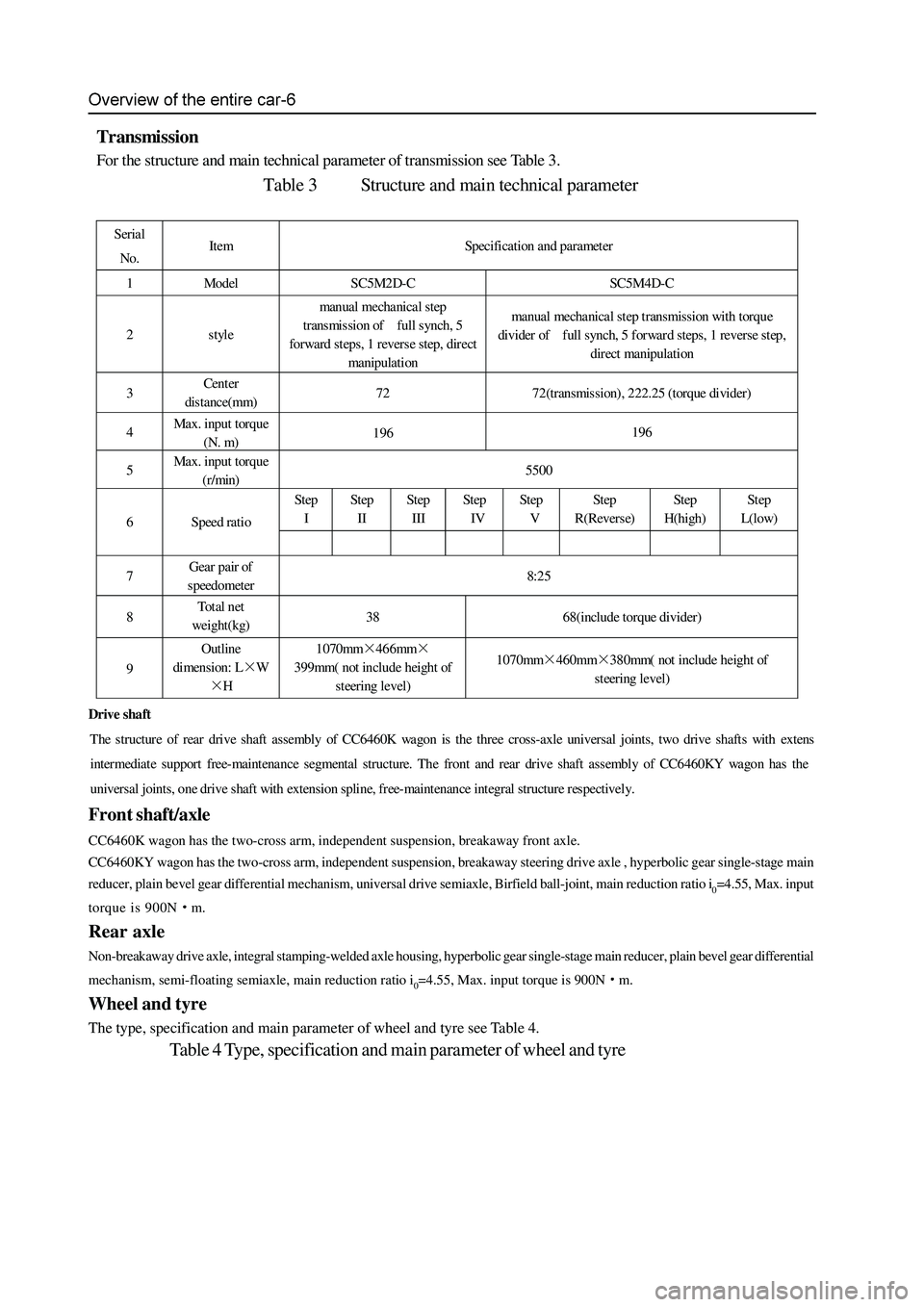
Transmission
For the structure and main technical parameter of transmission see Table 3.
Table 3 Structure and main technical parameter
Serial
No. Item Specification and parameter
1 Model SC5M2D-C SC5M4D-C
2 style manual mechanical step
transmission of full synch, 5
forward steps, 1 revers e step, direct
manipulation manual mechanical step transmission with torque
divider of full synch, 5 forward steps, 1 reverse step,
direct manipulation
3 Cent er
distance(mm) 72 72(transmission), 222.25 (torque divider)
4 Max. input torque
(N. m) 196 196
5 Max. input torque
(r/min) 5500
Step
I Step
II Step
III St ep
IV Step
V Step
R(Reverse) Step
H(high) St ep
L(low)
6 Speed ratio
7 Gear pair of
speedometer 8:25
8 To t a l n et
weight(kg) 38 68(include torque divider)
9 Outline
dimension: L×W
×H 1070mm×466mm×
399mm( not include height of
steering level) 1070mm×460mm×380mm( not include height of
steering level)
Drive shaft
The structure of rear drive shaft assembly of CC6460K wagon is the three cross-axle universal joints, two drive shafts with exten
s
intermediat e support free-maint enance segmental structure. The front and rear dr ive shaft assembly of CC6 460KY wa gon has the
universal joints, one drive shaft with extension spline, free-maintenance integral structure respectively.
Page 16 of 425

Overview of the entire car-7
Suspension
The front suspension is the torsion bar spring, double-cylinder inflatable hydraulic damper, transverse stabilizer rod, double
cross-arm independent suspension. The distance between the center of front shaft of lower arm fixing nut and level ground is
295mm±1mm.
The rear suspension is the four-connecting rod, coil spring, double-cylinder inflatable hydraulic damper, transverse stabilizer
rod, no indep endent suspension.
Carriage
Peripheral trapezoidal structure; welded by two box section longitudinal beams and several box or tube section cross beams.
Steering system
Pinion-and-rack power steering-gear, hydraulic assists steering. Breakaway front steering trapezoidal structure. Diameter of
quadriradistus steering disc φ380mm, adjustable angle, power-absorbing steering pipe. For main technical parameters of
steering s ystem refer to Table 5.
Table 5 Main technical parameter of steering system
Serial No. Item Parameter Serial No. Item Parameter
1 wheel camber 0°±30′ 6 Rotary round of
steering disc n 3.64
2 kingpin inclination 12°30′±30′ 7 Angle drive ratio of
steering system i0ω 18.2
3 kingpin castor 3°30′±30′ 8 Force drive ratio of
steering s ystem i0p 198.0
4 toe (mm) 0~2 9 Normal efficiency of
steering gear η+ ≥75%
5 Steering angle of
internal and external
wheel (°) 32/28 10 Revers e efficiency of
steering gear η- ≥60%
1.Adjustment of .4-Wheel Alignment
Test and adjust the front wheel alignment value and adjust the toe on the 4-Wheel Alignment meter.
a. Adjustment of kingpin castor: The standard value is 3°30′±30′(adjust the difference of left and right kingpin
castor to within 30′);
b. Adjustment of toe: The toe with standard value of 0~2mm is adjusted by rotating the steering cross rod. When adjust
the toe, it should rotate the cross brace in left and right side evenly. Tighten the lock nut after adjustment, the torque is
55 - 65N·m.
c. Centering and fix of steering wheel: according to the display of the alignment gauge, turn the front wheel to right
ahead, after removing the steering wheel without changing the position of steering lever, mount the steering wheel
with center aligned, the radials of the steering wheel shall be in the bilateral symmetry position, and the symbol of
Great wall on the steering wheel shall be in the confrontation position of the driver, tighten the nut, with a tightening
torque of 25 - 35N·m.
Left wheel left steering: 32, right wheel left steering:28;
Left wheel right steering:
28, right wheel right steering: 32;
b. Under the light condition of the car, the height between the center of front axis fixed bolt of the lower suspension arm to the
ground is 295
1mm, if the dimension is not within this scope, reach it through adjusting the torsion bar adjustment arm
bolt;
c. The reference dimension of the height of the car is : the left and right deviation is less than 10mm;
3. Checking the free gap of steering wheel:
Turn the orientation of the car to front, stop the engine, exert a force of about 4.9N on the steering wheel along the circumferential
direction to make the it turning to the left, there is resistance force, stop turning when the resistance force is growing; then turn
the steering wheel to the right, stop turning when the resistance force is felt to be growing; the radian value that the external edge
of steering wheel runs is the free gap of the steering wheel, its standard value shall be less than or equal to 20
, and the corner
from the central position to the left or right shall be no larger than 10.