2006 GREAT WALL HOVER transmission oil
[x] Cancel search: transmission oilPage 32 of 425

Clutch-2
Troubleshooting
failure cause inspection content
Shift difficulty or can not shift
Large free stroke of clut ch pedal clutch Pipe
has air
Failure of clutch cylinder
Failure of clutch master cylinder
The installation position of clutch disc is not
in position; large deviation; oil on the friction
lining or broken
The clutch disc is dirty or with foreign
material
Failure of clutch cover Adjust the free stroke of pedal
Discharge the air in clutch system
Replace
replace
Inspect the clutch disc; replace
Repair if necessary
Replace
Disengagement of transmission The clutch guide bearing is worn. Replace the guide bearing
Slide of clut ch
insufficient free stroke of clutch pedal
oil on the clutch disc friction lining or broken
failure of press disc
separation rocker arm assembly is blocked Adjust the free stroke of pedal
Inspect the clutch disc and replace it
Replace the clut ch cover
Check the separation rocker arm assembly
clutch clamping
stagnation/vibration oil on the clutch disc friction lining or broken
failure of press disc clutch membrane spring
is bend
loose of engine bracket Inspect the clutch disc and replace
Replace the clut ch cover
Correct the clutch membrane
Repair if necessary
Soft of clutch pedal clutch pip e has air
failure of clutch cylinder
failure of clutch master cylinder Discharge the air in clutch
replace
replace
Loud noise of clut ch
Component in clutch housing is loose
Throw-out bearing is worn or dirty
guide bearing is worn
separation rocker arm assembly or pull-rod is
blocked Repair if necessary
replace
replace
Repair if necessary
Page 36 of 425

Clutch-6
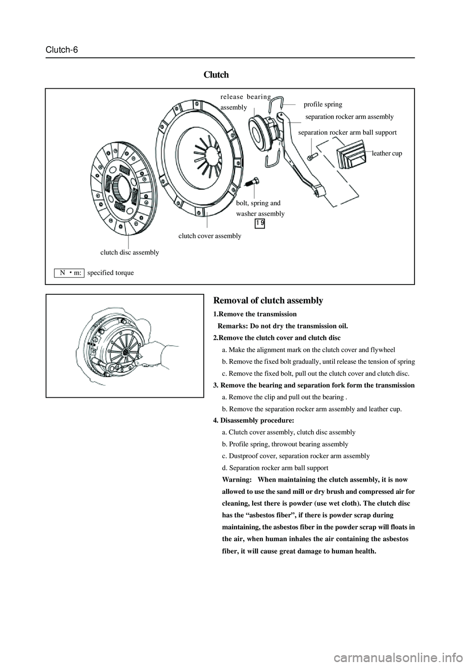
Clutch
4. Disassembly procedure:
a. Clutch cover assembly, clutch disc assembly
b. Profile spring, throwout bearing assembly
c. Dustproof cover, separation rocker arm assembly
d. Separation rocker arm ball support
Warning: When maintaining the clutch assembly, it is now
allowed to use the sand mill or dry brush and compressed air for
cleaning, lest there is powder (use wet cloth). The clutch disc
has the “asbestos fiber”, if there is powder scrap during
maintaining, the asbestos fiber in the powder scrap will floats in
the air, when human inhales the air containing the asbestos
fiber, it will cause great damage to human health.
Removal of clutch assembly
1.Remove the transmission
Remarks: Do not dry the transmission oil.
2.Remove the clutch cover and clutch disc
a. Make the alignment mark on the clutch cover and flywheel
b. Remove the fixed bolt gradually, until release the tension of spring
c. Remove the fixed bolt, pull out the clutch cover and clutch disc.
3. Remove the bearing and separation fork form the transmission
a. Remove the clip and pull out the bearing .
b. Remove the separation rocker arm assembly and leather cup.
clutch disc assembly
clutch cover assembly
bolt, spring and
washer assembly release bearing
assembly
profile spring
separation rocker arm assembly
separation rocker arm ball support
leather cup
N m: specified torque
Page 43 of 425

Inspection of SC5M2D-C transmission:
1.Check the oil level of transmission:
Screw off the oil discharge plug of the transmission; discharge all lubri-
cate oil; screw on the oil discharge plug to the specified torque; the
torque is: 30
35Nm. Fill the transmission with the transmission
oil through the oil filling port, oil number is hyperbolic gear oil SAE80W/
90, which meet API GL-4, oil capacity are 2.2L. Tighten the oil-filling
plug to the specified torque of 30
35Nm. (for area with high or
low temperature refer to the maintenance specification)
2. Replacement of oil seal of rear hosing:
The replacement of the oil seal of rear housing is shown in figure.
Disconnect the drive shaft from the rear housing; remove the oil seal
by the flat screwdriver, then use the special tools to knock the rear
housing oil seal in the rear housing. It should pay attention to the
installation of oil seal, shown as figure. Coat the lip of oil seal with the
specified transmission oil.
3. Removal, installation and inspection of transmission
The preoperation before removal and after installation of transmission
is: Remove and install the manipulator cover assembly, drain and fill
the transmission oil accordance with the regulation; after remove and
install the drive shaft. Separate each plug-in part from the vehicle
transmission .
4
Inspection of manipulator cover assembly
Shown as figure, remove the adhesive on the surface before installation,
use the screwdriver( M8
1.25) to clean the adhesive in the screw
hole; coat the installed part of bolt screw with the specified screw
adhesive. Firstly, install two positioning bolts A, then install other
two bolt A and bolt C respectively. The tightening torque of all bolts is
15
22Nm.
oil filling screw plug (SC1701005)
oil-drain screw-plug assembly (JK721701071)
rear housing oil seal
bolt C(SC-1704003)bolt A(SC-1704004)
Page 44 of 425

SC5M2D-C transmission assembly
handle of gearlever
dustproof seal cover
oil seal 39.65210
odometer driven gear assembly
odometer seating lock plate
cylindrical compression spring
1.05.841
bush
select & shift seating
N m: specified torque
Used component which can not be used any more.
Pregummed component
Use the special toolsmanipulator cover assembly
elastic cylindrical pin 6
22
rear housing assembly spring cylindrical pin
reverse lamp switch bracket
bearing housing assembly
clutch housing assembly
location compression
cylindrical pin
Page 64 of 425

Transmission-25
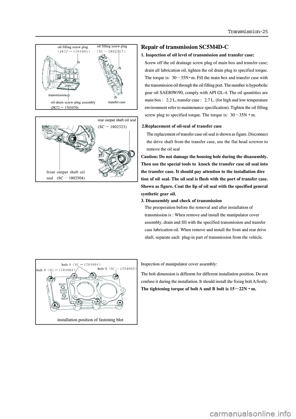
2.Replacement of oil-seal of transfer case
The replacement of transfer case oil seal is shown as figure. Disconnect
the drive shaft from the transfer case, use the flat head screwer to
remove the oil seal
Caution: Do not damage the housing hole during the disassembly.
Then use the special tools to knock the transfer case oil seal into
the transfer case. It should pay attention to the installation dire
tion of oil seal. The oil seal is flush with the port of transfer case.
Shown as figure. Coat the lip of oil seal with the specified general
synthetic gear oil.
3. Disassembly and check of transmission
The preoperation before the removal and after installation of
transmission is : When remove and install the manipulator cover
assembly, drain and fill with the specified transmission and transfer
case lubrication oil. When remove and install the front and rear drive
shaft, separate each plug-in part of transmission from the vehicle.
Inspection of manipulator cover assembly:
The bolt dimension is different for different installation position. Do not
confuse it during the installation. It should install the fixing bolt A firstly.
The tightening torque of bolt A and B bolt is 15
22Nm.
installation position of fastening blot
bolt
bolt bolt
Repair of transmission SC5M4D-C
1. Inspection of oil level of transmission and transfer case:
Screw off the oil drainage screw plug of main box and transfer case;
drain all lubrication oil, tighten the oil drain plug to specified torque.
The torque is: 30
35Nm. Fill the main box and transfer case with
the transmission oil through the oil filling port. The number is hyperbolic
gear oil SAE80W/90, comply with API GL-4. The oil quantities are
main box : 2.2 L, transfer case : 2.7 L. (for high and low temperature
environment refer to maintenance specification). Tighten the oil filling
screw plug to specified torque. The torque is: 30
35Nm.
front output shaft oil
seal (SC
1802504)
rear output shaft oil seal
(SC
1802323)
transmission
transfer case
oil filling screw plug
oil-drain screw-plug assembly
(JK72
1701070) oil filling screw plug
Page 66 of 425

Transmission-27
Manipulator cover assembly
Rear housing assembly
nut
reverse lock
assembly
manipulator
cover assembly
ball head
rubber cover
auxiliary steering
column stop platebush
ball head basewasher
pin
auxiliary steering
column assembly
handle of transfer case
ball head
hood
ball head
rubber cover
stop plate of
main bar
bush
ball head base
pin
washer
master control lever assembly
handle of
gearlever
N m: specified torque
Used component which can not be used any more.
odometer driven gear
assembly
odometer seating lock plate
14-19
14-19
oil seal
dustproof seal
guide bushing
rear housing
adjusting shim
24-33
26-36
aluminum gasket
mushroom lock spring
aluminum gasket
24-33
mushroom lock spring
26-3630-42
N m: specified torque
Used component which can not be used any more.
Pregummed component
Use the special tools
steel ball 7.938 (3)
Page 74 of 425

Transmission-35
Disassembly of rear output shaft assembly
a. Use the special tools to remove the lock nut
Caution: The tightening torque is 87-120N
m when in-
stall the lock nut.
b. Remove the ball bearing
Rear output shaft assembly
cRemove the oil guide plate
circlips for shafthigh and low
gear sleeve
needle bearing
high and low gear hub
needle bearing
low-speed driven gear
rear output shaft
ball bearing
spacing platesecond/ fourth drive gear hub
second/fourth
drive geared sleeve
sprocket needle bearing bushing
needle
bearing
drive sprocket
spacer of
drive sprocket
oil guide plate assembly
ball bearing
assembly
87-120
N m: specified torque
Used component which can not be used any more.
Use the special tools
dRemove the spacing ring
Page 78 of 425

Automatic transmission-2
Instruction for automatic transmission
1. M88 4-speed automatic transmission is equipped with the hydraulic torque converter and electric control system with locking.
When keep the stable forward status, the hydraulic torque converter can be locked automatically when the engine operates in low
speed, then reduce the unnecessary slide.
Figure 1.1 Electric automatic transmission control system
Figure 1.2 M88 4 speeds automatic transmission appearance figure (applied to 2 wheels driving)
2. The main advantage of the transmission is the application of transmission control unit (TCU). The control unit is the control
system based on the microprocessor system.. TCU control the shifting sensing and realize the Gear position shifting through the
signal of opening degree of throttle position, opening frequency of throttle position, engine speed, vehicle speed, transmission oil
temperature, gear position, mode selection and forced Gear reduction application.
3. TCU drives a variable pressure regulating solenoid valve to control three regulation valves and control the feeling of shifting.
Different transmission fluid temperatures are taken as one the main parameters to control the output pressure of the solenoid
valve, so as to keep consistent feeling of shifting within the normal operation scope.
4. The planning of shifting is very flexible. According to the car model, the different shifting plan is stored in the same TCU.
Generally speaking, the “economical mode” can increase the economical efficiency of the fuel and the driving performance of the
car to the maximum limit. The “dynamic mode” can bring into full play the drive performance of the car to the maximum limit. The
“winter mode” can make the car starting from shift 2.