2006 GREAT WALL HOVER oil level
[x] Cancel search: oil levelPage 16 of 425

Overview of the entire car-7
Suspension
The front suspension is the torsion bar spring, double-cylinder inflatable hydraulic damper, transverse stabilizer rod, double
cross-arm independent suspension. The distance between the center of front shaft of lower arm fixing nut and level ground is
295mm±1mm.
The rear suspension is the four-connecting rod, coil spring, double-cylinder inflatable hydraulic damper, transverse stabilizer
rod, no indep endent suspension.
Carriage
Peripheral trapezoidal structure; welded by two box section longitudinal beams and several box or tube section cross beams.
Steering system
Pinion-and-rack power steering-gear, hydraulic assists steering. Breakaway front steering trapezoidal structure. Diameter of
quadriradistus steering disc φ380mm, adjustable angle, power-absorbing steering pipe. For main technical parameters of
steering s ystem refer to Table 5.
Table 5 Main technical parameter of steering system
Serial No. Item Parameter Serial No. Item Parameter
1 wheel camber 0°±30′ 6 Rotary round of
steering disc n 3.64
2 kingpin inclination 12°30′±30′ 7 Angle drive ratio of
steering system i0ω 18.2
3 kingpin castor 3°30′±30′ 8 Force drive ratio of
steering s ystem i0p 198.0
4 toe (mm) 0~2 9 Normal efficiency of
steering gear η+ ≥75%
5 Steering angle of
internal and external
wheel (°) 32/28 10 Revers e efficiency of
steering gear η- ≥60%
1.Adjustment of .4-Wheel Alignment
Test and adjust the front wheel alignment value and adjust the toe on the 4-Wheel Alignment meter.
a. Adjustment of kingpin castor: The standard value is 3°30′±30′(adjust the difference of left and right kingpin
castor to within 30′);
b. Adjustment of toe: The toe with standard value of 0~2mm is adjusted by rotating the steering cross rod. When adjust
the toe, it should rotate the cross brace in left and right side evenly. Tighten the lock nut after adjustment, the torque is
55 - 65N·m.
c. Centering and fix of steering wheel: according to the display of the alignment gauge, turn the front wheel to right
ahead, after removing the steering wheel without changing the position of steering lever, mount the steering wheel
with center aligned, the radials of the steering wheel shall be in the bilateral symmetry position, and the symbol of
Great wall on the steering wheel shall be in the confrontation position of the driver, tighten the nut, with a tightening
torque of 25 - 35N·m.
Left wheel left steering: 32, right wheel left steering:28;
Left wheel right steering:
28, right wheel right steering: 32;
b. Under the light condition of the car, the height between the center of front axis fixed bolt of the lower suspension arm to the
ground is 295
1mm, if the dimension is not within this scope, reach it through adjusting the torsion bar adjustment arm
bolt;
c. The reference dimension of the height of the car is : the left and right deviation is less than 10mm;
3. Checking the free gap of steering wheel:
Turn the orientation of the car to front, stop the engine, exert a force of about 4.9N on the steering wheel along the circumferential
direction to make the it turning to the left, there is resistance force, stop turning when the resistance force is growing; then turn
the steering wheel to the right, stop turning when the resistance force is felt to be growing; the radian value that the external edge
of steering wheel runs is the free gap of the steering wheel, its standard value shall be less than or equal to 20
, and the corner
from the central position to the left or right shall be no larger than 10.
Page 35 of 425

Clutch-5
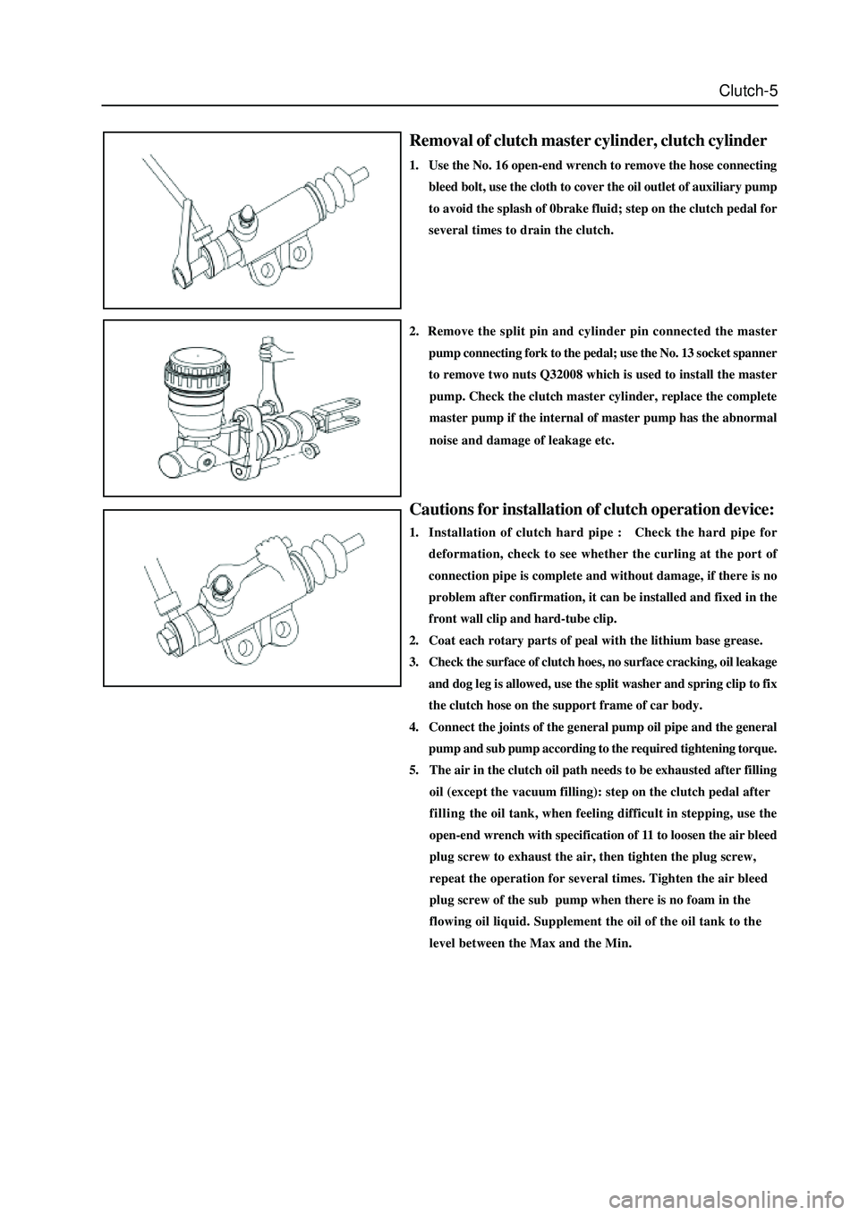
Removal of clutch master cylinder, clutch cylinder
1. Use the No. 16 open-end wrench to remove the hose connecting
bleed bolt, use the cloth to cover the oil outlet of auxiliary pump
to avoid the splash of 0brake fluid; step on the clutch pedal for
several times to drain the clutch.
Cautions for installation of clutch operation device:
1. Installation of clutch hard pipe : Check the hard pipe for
deformation, check to see whether the curling at the port of
connection pipe is complete and without damage, if there is no
problem after confirmation, it can be installed and fixed in the
front wall clip and hard-tube clip.
2. Coat each rotary parts of peal with the lithium base grease.
3. Check the surface of clutch hoes, no surface cracking, oil leakage
and dog leg is allowed, use the split washer and spring clip to fix
the clutch hose on the support frame of car body.
4. Connect the joints of the general pump oil pipe and the general
2. Remove the split pin and cylinder pin connected the master
pump connecting fork to the pedal; use the No. 13 socket spanner
to remove two nuts Q32008 which is used to install the master
pump. Check the clutch master cylinder, replace the complete
master pump if the internal of master pump has the abnormal
noise and damage of leakage etc.
pump and sub pump according to the required tightening torque.
5. The air in the clutch oil path needs to be exhausted after filling
oil (except the vacuum filling): step on the clutch pedal after
fillingthe oil tank, when feeling difficult in stepping, use the
open-end wrench with specification of 11 to loosen the air bleed
plug screw to exhaust the air, then tighten the plug screw,
repeat the operation for several times. Tighten the air bleed
plug screw of the sub pump when there is no foam in the
flowing oil liquid. Supplement the oil of the oil tank to the
level between the Max and the Min.
Page 43 of 425

Inspection of SC5M2D-C transmission:
1.Check the oil level of transmission:
Screw off the oil discharge plug of the transmission; discharge all lubri-
cate oil; screw on the oil discharge plug to the specified torque; the
torque is: 30
35Nm. Fill the transmission with the transmission
oil through the oil filling port, oil number is hyperbolic gear oil SAE80W/
90, which meet API GL-4, oil capacity are 2.2L. Tighten the oil-filling
plug to the specified torque of 30
35Nm. (for area with high or
low temperature refer to the maintenance specification)
2. Replacement of oil seal of rear hosing:
The replacement of the oil seal of rear housing is shown in figure.
Disconnect the drive shaft from the rear housing; remove the oil seal
by the flat screwdriver, then use the special tools to knock the rear
housing oil seal in the rear housing. It should pay attention to the
installation of oil seal, shown as figure. Coat the lip of oil seal with the
specified transmission oil.
3. Removal, installation and inspection of transmission
The preoperation before removal and after installation of transmission
is: Remove and install the manipulator cover assembly, drain and fill
the transmission oil accordance with the regulation; after remove and
install the drive shaft. Separate each plug-in part from the vehicle
transmission .
4
Inspection of manipulator cover assembly
Shown as figure, remove the adhesive on the surface before installation,
use the screwdriver( M8
1.25) to clean the adhesive in the screw
hole; coat the installed part of bolt screw with the specified screw
adhesive. Firstly, install two positioning bolts A, then install other
two bolt A and bolt C respectively. The tightening torque of all bolts is
15
22Nm.
oil filling screw plug (SC1701005)
oil-drain screw-plug assembly (JK721701071)
rear housing oil seal
bolt C(SC-1704003)bolt A(SC-1704004)
Page 64 of 425

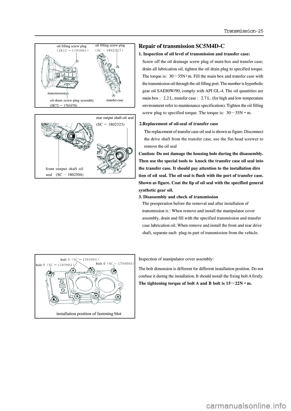
Transmission-25
2.Replacement of oil-seal of transfer case
The replacement of transfer case oil seal is shown as figure. Disconnect
the drive shaft from the transfer case, use the flat head screwer to
remove the oil seal
Caution: Do not damage the housing hole during the disassembly.
Then use the special tools to knock the transfer case oil seal into
the transfer case. It should pay attention to the installation dire
tion of oil seal. The oil seal is flush with the port of transfer case.
Shown as figure. Coat the lip of oil seal with the specified general
synthetic gear oil.
3. Disassembly and check of transmission
The preoperation before the removal and after installation of
transmission is : When remove and install the manipulator cover
assembly, drain and fill with the specified transmission and transfer
case lubrication oil. When remove and install the front and rear drive
shaft, separate each plug-in part of transmission from the vehicle.
Inspection of manipulator cover assembly:
The bolt dimension is different for different installation position. Do not
confuse it during the installation. It should install the fixing bolt A firstly.
The tightening torque of bolt A and B bolt is 15
22Nm.
installation position of fastening blot
bolt
bolt bolt
Repair of transmission SC5M4D-C
1. Inspection of oil level of transmission and transfer case:
Screw off the oil drainage screw plug of main box and transfer case;
drain all lubrication oil, tighten the oil drain plug to specified torque.
The torque is: 30
35Nm. Fill the main box and transfer case with
the transmission oil through the oil filling port. The number is hyperbolic
gear oil SAE80W/90, comply with API GL-4. The oil quantities are
main box : 2.2 L, transfer case : 2.7 L. (for high and low temperature
environment refer to maintenance specification). Tighten the oil filling
screw plug to specified torque. The torque is: 30
35Nm.
front output shaft oil
seal (SC
1802504)
rear output shaft oil seal
(SC
1802323)
transmission
transfer case
oil filling screw plug
oil-drain screw-plug assembly
(JK72
1701070) oil filling screw plug
Page 96 of 425

Automatic transmission-20
Figure 3.17 reverse lock valve
12. Primary regulating valve
Primary regulating valve (PRV) (refer to Figure 3.18) can regulate the line pressure of transmission (or pump output
pressure). The valve can give the high or low line pressure according to the on/off status of S6. When S6 is in on or off status,
the pressure S6 is applied on PRV, move it and has the action of spring force. Open the line pressure loop to turn on the inlet
of pump to reduce the line pressure. Generally, the line pressure is small when the throttle position is opened lightly and in
patrol status. It will cause the closing of S6 when the opening degree of throttle position is large and because the high line
pressure valve
For all shifting pressures are controlled by output of separation brake belt , clutch regulating valve and S5, so all step control
of line pressure has not affect on effect of shifting sensing.
By the oil inlet of torque converter, PRV also adjust the oil supply of hydraulic torque converter. The level effect of PRV
should ensure the priority of valve, i.e. it can keep the line pressure in low engine speed condition. When the speed of engine
is increased and the pump supplies excess oil, the PRV acts to open the torque converter oil inlet cover to increase the pressure
of torque converter. If the oil amount is beyond the requirement of transmission, PRV will act further to allow the oil return
to the suction inlet.
Figure 3.18 Primary regulating valve
Figure 3.19 Torque converter on/off regulating valve
The torque converter regulating valve (refer to Figure 3.19) adjusts the pressure applied on torque converter clutch oil.
According to the signal pressure form loop S5, adjust the oil flow status from line pressure loop in valve. With the change of
pressure signal of loop S5, the engagement and disengagement of torque converter clutch can be finished by electric control.
13. Torque converter on/off regulating valve
Page 125 of 425

Automatic transmission-49
The distribution of FAQ table is shown as follows:
Table 6.2.1 Drive failure Table 6.2.3 Shift quality failure
Table 6.2.2 Shift mode failure Table 6.2.4 Disassembly failure
failure Possible reason Corresponding measure
“D”-Gear operation
has not drive The automatic transmission fluid is insufficient.
The oil-entering of C1/C2 piston is blocked.
The “Z” is assembled incorrectly.
The primary regulating valve plug is opened.
The overspeed shaft or input shaft sealing ring is
failure.
3→4, 1→2 single-way clut ch is installed in revers e or
failure. Check the liquid level. Fill it up if necessary.
Check and wash the C1/C2 oil inlet device.
Reinstall the “Z” connection.
Remove, wash and reinstall the primary
regulating valve.
Check and replace it if necessary.
Check and replace it if necessary.
The reverse shifting
operation is without
drive.
The manual 1
st-Gear
has not engine
brake.
The engine brake is
normal in manual
1
st-Gear. The input shaft oil seal ring is damaged.
The rear brake belt or servo system is faulty.
C3, C3 wheel shaft or C1/C2 cylinder are out of work. Check and replace it if necessary.
Test the servo system or replace the rear brake
belt according to the requirement.
Test the failure C3, C3 wheel axle or C1/C2
cylinder.
Repair it in time if necessary.
“D” –Gear and reverse
–Gear operation is
without drive. The primary regulating valve is blocked.
The pump gear is damaged.
Take out the output shaft clasp. Det ect and clean the primary regulating valve.
Check and replace the pump gear if necessary.
Check and repair it if necessary.
Only can 2→3 shifting
(can not realize the
4
th-Gear and 1st-Gear) S1 is closed always. Test the S1. Repair or replace it if necessary.
Test the failure of S1 12V power supply
voltage or wire bundle.
Only can 1→4 shifting
1→3→4 shifting (1
→2 shifting delay). S1 is opened always Test the S1. Repair or replace it if necessary.
Test the failure of S1 12V power supply
voltage or wire bundle.
Only can 4→3 shifting S2 is closed always.
Test the S2. Repair or replace it if necessary.
Test the failure of circuit break or wire bundle.
1→2→neutral position
shifting (1st-Gear
transition) S2 is opened always Test the S2. Repair or replace it if necessary.
Test the failure of circuit break or wire bundle.
Only can 1→3 shifting B1 is out of work
The brake belt is loose.
The front servo piston or oil s eal is out of work.
S1/S2 ball spool is reinstalled in wrong place. Test and adjust it according to the requirement.
Test and maintain it according to the
requirement. Test and replace or reinstall it according
to the requirement.
Only can 1→3→4
shifting The small O-ring of front s ervo piston is invalid or
lost.
2→3 Gear position shifting valve is blocked. Det ect the O-ring. Process the replacement or
reinstallation if necessary. Detect the 2→3
Gear shifting valve; Process the maintenance
or replacement according to the requirement.
Only can 1→2→1
shifting C1 is invalid or 3rd-Gear and 4th-Gear is loose. (give
to 1st-Gear in 3rd-gear; give to 2nd-Gear in 4th-Gear) Det ect the clutch C1. Repair or replace it if
necessary.
Can not realize the
man ual 4→3, 3→2, 2
→1 Overspeed clutch /ball spool has displacement.
C4 is invalid. Detect the ball spool. Process the replacement
or reinstallation according to the requirement.
Det ect the C4. Repair C4 or r eplace the C4
wave pan according to the necessary.
Page 129 of 425

Adjustment
Hydraulic system
Following parts is the detailed description for self-detection procedure pointed to the condition occurred in chapter
6. including the condition indicated the failure, to point the problem existed in the hydraulic system.
It should select the proper procedure from the following primary detection when adjust the transmission.
Detection process of transmission fluid
Detect the manual linkage adjusting system(refer to factory manual of car)
Detect the engine idle speed
Anchoring test (beyond the scope of the maintenance manual)
On-road test (beyond the scope of the maintenance manual)
Detection procedure of transmission fluid level
1. General
The process is used to detect the level of vehicle transmission fluid. It will cause the failure or delay of transmission shifting if
the level is low than required value and the vehicle does not reach the drive temperature.
Firstly, process the transmission diagnosis information detection for vehicle (refer to chapter 6). If found the failure of sensor,
then it maybe caused by transmission fluid level is less than specified value.
It should detect whether has the abnormal delay and Gear-position condition when select the forward or reverse-gear by driving
the vehicle. One feature of oil level less than normal value is that the vehicle has the gear-position delay and lack condition when
the vehicle is in steering. The previous problem will occur when the transmission fluid temperature is low.
When the oil temperature is medium and vehicle speed failure is recorded, the gear-position lose condition
will not occurs any longer, it means that needs to fill the transmission with the transmission fluid.
2. Detection of transmission fluid level
When fill up or replace the transmission fluid, it must use the Castrol TQ95 automatic transmission fluid (ATF) or other
permissive oil. It will damage the performance and service life of transmission if use the unpermissive transmission fluid.
Please ensure the transmission fluid level is correct. The transmission also can be damaged if the transmission fluid level is
incorrect.
The setting procedure of transmission fluid level is shown as follows:
Caution:
When the transmission is in operating temperature, the hot transmission fluid may flow out form the
housing if remove the filling plug.
a. If the vehicle is in operating temperature, allow two hours time for cooling before add the transmission fluid, but
it must not more than 4 hours (this will make the transmission locate in the correct temperature range). When the
temperature is overheating, the transmission fluid level will higher than the plug port. Removal of plug will cause
the transmission fluid flows out from the oil filling port, then cause the low level of transmission fluid.
b. The gear-position of transmission is in parking-Gear (P-Gear), shut off the engine.
c. Lifting the vehicle (or parking above the trench).
d. Clean the around of plug when remove it. Then remove and clean the plug and check the O-ring for damage. Install
the oil filling pump in the oil filling hole.
e. Lower the vehicle; the oil filling pump will be connected to the vehicle at this time. Fill the transmission with the
oil partially. Then start the vehicle in P-Gear to rotate the engine in idle speed. Step down the foot brake, pull the
shifting lever in each gear-position in circulation and add the transmission fluid until the action of each gear-
position can be sensed.
f. Shut down the engine; lift the vehicle; ensure the vehicle is always in horizontal.
g. Remove the filling plug 3 minutes after the engine is shut off, but must not be no more than1 hour. At this time, the
correct level position should be in the bottom of oil filling hole. If does not reach the liquid level position, then fill
with few transmission fluid to make it reach the correct level.
h. Replace the transmission; clean the residual transmission fluid on the transmission and
vehicle.
i. Tighten the transmission plug to the specified torque of 30
35Nm.
Page 130 of 425

3. Oil filling of service after sales
Set the liquid level position correctly; the procedure is shown as follows:
a. Shut down the engine; place the gear-position in the P-Gear.
b . Lift the vehicle (or place it above the trench).
c. Clean the around of plug before remove it. Remove the oil plug and check the O-ring for damage, finally connect the oil filling
pump to the oil filling hole.
d. Lower the vehicle and oil filling pump to the ground; fill with the transmission fluid partially. The general oil filling amount
is shown as follows:
If in the status of transmission hydraulic torque converter is empty: 8.0 L
If in the status of transmission hydraulic torque converter is full: 3.8 L
e. When start the vehicle in P-Gear, rotate the engine in idle speed. Step down the foot brake, pull the shifting lever in each gear-
position in circulation and add the transmission fluid until the action of each gear-position can be sensed.
f. Then fill with 0.5L transmission fluid (ATF) additionally.
g. Shut off the engine, lift the vehicle; take off the pump and replace the plug. Ensure the plug is tightened according to the
specification.
h. Then pull the vehicle throttle position for slight opening to make the vehicle runs for 3.5
4.5km; the rotary speed of engine
is no more than 2500r/min; then the transmission fluid temperature will in the scope of 50
60.
i. The engine is in idle-speed; pull the hand brake to make the shifting lever circuits in each gear-position horizontal status.
k. Remove the filling plug 3 minutes after the engine is shut off, but must be no more than1 hour. At this time, the correct
level position should be in the bottom of oil filling hole. If does not reach the liquid level position, then fill with few
transmission fluid (ATF) to meet the requirement.
l. Reinsert the transmission fluid plug, remove the residual transmission fluid around the vehicle and transmission; tighten the
plug to the specified torque.
4. Replace the ATF
Please notice that the color of TQ95 automatic transmission oil will be faded in the normal operation of transmission; it will be
turn into the deep brown or even in black. It will not affect the performance of ATF. It means that the fading of transmission
fluid not always means to replace the transmission fluid.
If the transmission temperature is raised, the ATF will be burnt. In this condition, ATF will change into black and with special
sulfur smell. The smell of the ATF means the oil is burnt.
If the ATF is burnt, it will cause the damage of transmission (the clutch assembly is damaged at least).At this time, it should
disassembly the transmission and process the necessary detection.
Electronic calibration
1. Idle-speed calibration
The idle-speed calibration is introduced in detail in the vehicle factory manual.
2 Calibration of position of throttle position
If the throttle position information stored in TCU is lost or not in application scope. It can be reestablished according to the
following program as the diagnosis error information.
a. Check whether the engine idle speed is in required range.
b. In the status of shutting off of air-condition, make the engine is in “D” –Gear for 60s,then the reference point with opening
degree of 0
of throttle position is reset in TCU.
Shut off the engine; switch on the ignition device, step the accelerator pedal to bottom for 60s, then the reference point with opening
degree of 100
of throttle position is reset in TCU.
3. Clear of throttle position
The clear process set by learning throttle position is necessary for M88 transmission TCU.
4. Car code
For M88 transmission, the car code is unnecessary.