2006 GREAT WALL HOVER check transmission fluid
[x] Cancel search: check transmission fluidPage 124 of 425

Automatic transmission-48
s oleno id
valve Condition Transmission operation
1 Opened
always 1st-Gear replaces 2nd-Gear; 4th-Gear replaces 3rd-Gear. It causes the car form the G ear shift of 1
→1→4→4 when accelerate form static. The transmission stay longer time in Gear; worse 1→4
shift feeling.
Closed always 2nd-Gear replaces 1st-Gear; 3rd-Gear replaces 4th-Gear. It causes the car form the G ear shift of 2
→2→3→3 when accelerate form static. It is said that starts form 2nd-Gear.
2 Closed always 4th-Gear replaces 1st-Gear; 3rd-Gear replaces 2nd-Gear. It causes the car form the G ear shift of 2
→2→3→3 when accelerate form static. That is saying that start form 4th-Gear.
Opened
always 2nd-Gear replaces 3rd-Gear; 1st-Gear replace 4th-Gear.
It cause the car is shifted form 1st-Gear to 2nd-Gear, then from 2nd-G ear to Gear when accelerate
form static. It will feel the transmission is in free gear position after 2→1 Gear shift.
1&2 Opened
always Can not realize the reverse gear; only has 1st-Gear operation.
3 Closed always Following shifts are bad. (2→3 is worst ):1→3, 1→4, 2→3, 2→4, 4→2, 4→1
Opened
always Following gear shifts are worse: 3→4, 4→3, 3→2。
It may cause the gear slide when the hydraulic torque converter is locked.
4 Closed always Following gear shifts are worse:
1→2, 1→3, 1→4, 2→3, 2→4, 3→1, 3→2, (including manual) 3→4, 4→1, 4→3
Opened
always Following gear shifts are worse: (1→2 is worst) 2→4, 3→2 It may cause the gear slide when
the hydraulic torque converter is locked.
6 Closed always The line pressure is high always.
Opened
always The line pressure is low always. So it cause the slide between gears. The clutch C1 and brake belt
B1 will be burned.
7 Closed always The hydraulic torque converter is without lock.
Opened
always The hydraulic torque converter is locked in 3rd-Gear and 4th-Gear. It cause the car generates the
vibration in low-speed status.
Table 6.1.2 Operation of transmission when ON/OFF solenoid valve is faulty
Mechanical detection
1.Inspection of transmission on car
It should process the following detections before disassemble the transmission:
process the on-road drive test to determine the failure cause .(according to requirement)
Detect the standard of transmission fluid. (refer to 7.2.1)
Ensure the transmission fluid in not overheated. (Normal color and smell)
Detect the failure information.
Check the battery terminal and grounding for corrosion or loose.
The engine speed is within the specified value in manual.
Check the cooling system for normal operation.
All power supply and plug wires is tight and not loose.
Check the transmission fluid, ensure the oil pan is without other martial material or pollutant.
2. Oil leakage detection
It should wash the polluted part of the transmission before select the oil leakage part, then drive the car.
When detect the leakage part of the rear servo system, it should lift the car by lifter firstly, then switch the gear to reverse
gear within 10s.
When detect the leakage part of front servo system, it should lift the car by lifter firstly, then switch the gear to gear-2
(winter mode).
The time switched to 2nd-Gear should be no more than 10s to avoid the oil in the torque converter is overheated.
3. FAQ table
Page 125 of 425

Automatic transmission-49
The distribution of FAQ table is shown as follows:
Table 6.2.1 Drive failure Table 6.2.3 Shift quality failure
Table 6.2.2 Shift mode failure Table 6.2.4 Disassembly failure
failure Possible reason Corresponding measure
“D”-Gear operation
has not drive The automatic transmission fluid is insufficient.
The oil-entering of C1/C2 piston is blocked.
The “Z” is assembled incorrectly.
The primary regulating valve plug is opened.
The overspeed shaft or input shaft sealing ring is
failure.
3→4, 1→2 single-way clut ch is installed in revers e or
failure. Check the liquid level. Fill it up if necessary.
Check and wash the C1/C2 oil inlet device.
Reinstall the “Z” connection.
Remove, wash and reinstall the primary
regulating valve.
Check and replace it if necessary.
Check and replace it if necessary.
The reverse shifting
operation is without
drive.
The manual 1
st-Gear
has not engine
brake.
The engine brake is
normal in manual
1
st-Gear. The input shaft oil seal ring is damaged.
The rear brake belt or servo system is faulty.
C3, C3 wheel shaft or C1/C2 cylinder are out of work. Check and replace it if necessary.
Test the servo system or replace the rear brake
belt according to the requirement.
Test the failure C3, C3 wheel axle or C1/C2
cylinder.
Repair it in time if necessary.
“D” –Gear and reverse
–Gear operation is
without drive. The primary regulating valve is blocked.
The pump gear is damaged.
Take out the output shaft clasp. Det ect and clean the primary regulating valve.
Check and replace the pump gear if necessary.
Check and repair it if necessary.
Only can 2→3 shifting
(can not realize the
4
th-Gear and 1st-Gear) S1 is closed always. Test the S1. Repair or replace it if necessary.
Test the failure of S1 12V power supply
voltage or wire bundle.
Only can 1→4 shifting
1→3→4 shifting (1
→2 shifting delay). S1 is opened always Test the S1. Repair or replace it if necessary.
Test the failure of S1 12V power supply
voltage or wire bundle.
Only can 4→3 shifting S2 is closed always.
Test the S2. Repair or replace it if necessary.
Test the failure of circuit break or wire bundle.
1→2→neutral position
shifting (1st-Gear
transition) S2 is opened always Test the S2. Repair or replace it if necessary.
Test the failure of circuit break or wire bundle.
Only can 1→3 shifting B1 is out of work
The brake belt is loose.
The front servo piston or oil s eal is out of work.
S1/S2 ball spool is reinstalled in wrong place. Test and adjust it according to the requirement.
Test and maintain it according to the
requirement. Test and replace or reinstall it according
to the requirement.
Only can 1→3→4
shifting The small O-ring of front s ervo piston is invalid or
lost.
2→3 Gear position shifting valve is blocked. Det ect the O-ring. Process the replacement or
reinstallation if necessary. Detect the 2→3
Gear shifting valve; Process the maintenance
or replacement according to the requirement.
Only can 1→2→1
shifting C1 is invalid or 3rd-Gear and 4th-Gear is loose. (give
to 1st-Gear in 3rd-gear; give to 2nd-Gear in 4th-Gear) Det ect the clutch C1. Repair or replace it if
necessary.
Can not realize the
man ual 4→3, 3→2, 2
→1 Overspeed clutch /ball spool has displacement.
C4 is invalid. Detect the ball spool. Process the replacement
or reinstallation according to the requirement.
Det ect the C4. Repair C4 or r eplace the C4
wave pan according to the necessary.
Page 129 of 425
Adjustment
Hydraulic system
Following parts is the detailed description for self-detection procedure pointed to the condition occurred in chapter
6. including the condition indicated the failure, to point the problem existed in the hydraulic system.
It should select the proper procedure from the following primary detection when adjust the transmission.
Detection process of transmission fluid
Detect the manual linkage adjusting system(refer to factory manual of car)
Detect the engine idle speed
Anchoring test (beyond the scope of the maintenance manual)
On-road test (beyond the scope of the maintenance manual)
Detection procedure of transmission fluid level
1. General
The process is used to detect the level of vehicle transmission fluid. It will cause the failure or delay of transmission shifting if
the level is low than required value and the vehicle does not reach the drive temperature.
Firstly, process the transmission diagnosis information detection for vehicle (refer to chapter 6). If found the failure of sensor,
then it maybe caused by transmission fluid level is less than specified value.
It should detect whether has the abnormal delay and Gear-position condition when select the forward or reverse-gear by driving
the vehicle. One feature of oil level less than normal value is that the vehicle has the gear-position delay and lack condition when
the vehicle is in steering. The previous problem will occur when the transmission fluid temperature is low.
When the oil temperature is medium and vehicle speed failure is recorded, the gear-position lose condition
will not occurs any longer, it means that needs to fill the transmission with the transmission fluid.
2. Detection of transmission fluid level
When fill up or replace the transmission fluid, it must use the Castrol TQ95 automatic transmission fluid (ATF) or other
permissive oil. It will damage the performance and service life of transmission if use the unpermissive transmission fluid.
Please ensure the transmission fluid level is correct. The transmission also can be damaged if the transmission fluid level is
incorrect.
The setting procedure of transmission fluid level is shown as follows:
Caution:
When the transmission is in operating temperature, the hot transmission fluid may flow out form the
housing if remove the filling plug.
a. If the vehicle is in operating temperature, allow two hours time for cooling before add the transmission fluid, but
it must not more than 4 hours (this will make the transmission locate in the correct temperature range). When the
temperature is overheating, the transmission fluid level will higher than the plug port. Removal of plug will cause
the transmission fluid flows out from the oil filling port, then cause the low level of transmission fluid.
b. The gear-position of transmission is in parking-Gear (P-Gear), shut off the engine.
c. Lifting the vehicle (or parking above the trench).
d. Clean the around of plug when remove it. Then remove and clean the plug and check the O-ring for damage. Install
the oil filling pump in the oil filling hole.
e. Lower the vehicle; the oil filling pump will be connected to the vehicle at this time. Fill the transmission with the
oil partially. Then start the vehicle in P-Gear to rotate the engine in idle speed. Step down the foot brake, pull the
shifting lever in each gear-position in circulation and add the transmission fluid until the action of each gear-
position can be sensed.
f. Shut down the engine; lift the vehicle; ensure the vehicle is always in horizontal.
g. Remove the filling plug 3 minutes after the engine is shut off, but must not be no more than1 hour. At this time, the
correct level position should be in the bottom of oil filling hole. If does not reach the liquid level position, then fill
with few transmission fluid to make it reach the correct level.
h. Replace the transmission; clean the residual transmission fluid on the transmission and
vehicle.
i. Tighten the transmission plug to the specified torque of 30
35Nm.
Page 130 of 425
3. Oil filling of service after sales
Set the liquid level position correctly; the procedure is shown as follows:
a. Shut down the engine; place the gear-position in the P-Gear.
b . Lift the vehicle (or place it above the trench).
c. Clean the around of plug before remove it. Remove the oil plug and check the O-ring for damage, finally connect the oil filling
pump to the oil filling hole.
d. Lower the vehicle and oil filling pump to the ground; fill with the transmission fluid partially. The general oil filling amount
is shown as follows:
If in the status of transmission hydraulic torque converter is empty: 8.0 L
If in the status of transmission hydraulic torque converter is full: 3.8 L
e. When start the vehicle in P-Gear, rotate the engine in idle speed. Step down the foot brake, pull the shifting lever in each gear-
position in circulation and add the transmission fluid until the action of each gear-position can be sensed.
f. Then fill with 0.5L transmission fluid (ATF) additionally.
g. Shut off the engine, lift the vehicle; take off the pump and replace the plug. Ensure the plug is tightened according to the
specification.
h. Then pull the vehicle throttle position for slight opening to make the vehicle runs for 3.5
4.5km; the rotary speed of engine
is no more than 2500r/min; then the transmission fluid temperature will in the scope of 50
60.
i. The engine is in idle-speed; pull the hand brake to make the shifting lever circuits in each gear-position horizontal status.
k. Remove the filling plug 3 minutes after the engine is shut off, but must be no more than1 hour. At this time, the correct
level position should be in the bottom of oil filling hole. If does not reach the liquid level position, then fill with few
transmission fluid (ATF) to meet the requirement.
l. Reinsert the transmission fluid plug, remove the residual transmission fluid around the vehicle and transmission; tighten the
plug to the specified torque.
4. Replace the ATF
Please notice that the color of TQ95 automatic transmission oil will be faded in the normal operation of transmission; it will be
turn into the deep brown or even in black. It will not affect the performance of ATF. It means that the fading of transmission
fluid not always means to replace the transmission fluid.
If the transmission temperature is raised, the ATF will be burnt. In this condition, ATF will change into black and with special
sulfur smell. The smell of the ATF means the oil is burnt.
If the ATF is burnt, it will cause the damage of transmission (the clutch assembly is damaged at least).At this time, it should
disassembly the transmission and process the necessary detection.
Electronic calibration
1. Idle-speed calibration
The idle-speed calibration is introduced in detail in the vehicle factory manual.
2 Calibration of position of throttle position
If the throttle position information stored in TCU is lost or not in application scope. It can be reestablished according to the
following program as the diagnosis error information.
a. Check whether the engine idle speed is in required range.
b. In the status of shutting off of air-condition, make the engine is in “D” –Gear for 60s,then the reference point with opening
degree of 0
of throttle position is reset in TCU.
Shut off the engine; switch on the ignition device, step the accelerator pedal to bottom for 60s, then the reference point with opening
degree of 100
of throttle position is reset in TCU.
3. Clear of throttle position
The clear process set by learning throttle position is necessary for M88 transmission TCU.
4. Car code
For M88 transmission, the car code is unnecessary.
Page 131 of 425
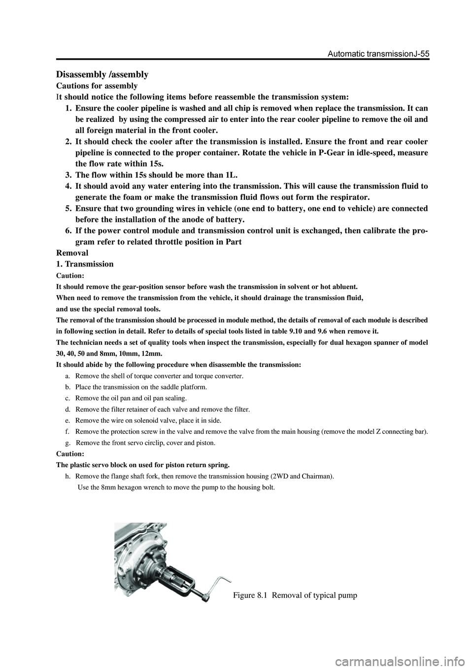
Figure 8.1 Removal of typical pump
Disassembly /assembly
Cautions for assembly
It should notice the following items before reassemble the transmission system:
1. Ensure the cooler pipeline is washed and all chip is removed when replace the transmission. It can
be realized by using the compressed air to enter into the rear cooler pipeline to remove the oil and
all foreign material in the front cooler.
2. It should check the cooler after the transmission is installed. Ensure the front and rear cooler
pipeline is connected to the proper container. Rotate the vehicle in P-Gear in idle-speed, measure
the flow rate within 15s.
3. The flow within 15s should be more than 1L.
4. It should avoid any water entering into the transmission. This will cause the transmission fluid to
generate the foam or make the transmission fluid flows out form the respirator.
5. Ensure that two grounding wires in vehicle (one end to battery, one end to vehicle) are connected
before the installation of the anode of battery.
6. If the power control module and transmission control unit is exchanged, then calibrate the pro-
gram refer to related throttle position in Part
Removal
1. Transmission
Caution:
It should remove the gear-position sensor before wash the transmission in solvent or hot abluent.
When need to remove the transmission from the vehicle, it should drainage the transmission fluid,
and use the special removal tools.
The removal of the transmission should be processed in module method, the details of removal of each module is described
in following section in detail. Refer to details of special tools listed in table 9.10 and 9.6 when remove it.
The technician needs a set of quality tools when inspect the transmission, especially for dual hexagon spanner of model
30, 40, 50 and 8mm, 10mm, 12mm.
It should abide by the following procedure when disassemble the transmission:
a. Remove the shell of torque converter and torque converter.
b. Place the transmission on the saddle platform.
c. Remove the oil pan and oil pan sealing.
d. Remove the filter retainer of each valve and remove the filter.
e. Remove the wire on solenoid valve, place it in side.
f. Remove the protection screw in the valve and remove the valve from the main housing (remove the model Z connecting bar).
g. Remove the front servo circlip, cover and piston.
Caution:
The plastic servo block on used for piston return spring.
h. Remove the flange shaft fork, then remove the transmission housing (2WD and Chairman).
Use the 8mm hexagon wrench to move the pump to the housing bolt.
Page 141 of 425

Figure 8.19 Position of thrust bearing and sealing pad
4. Rear servo assembly
Install the rear servo assembly (Refer to Figure 8.18), the procedure is shown as follows:
a. Check the servo piston O-ring and washer for damage.
b. Use the transmission fluid to lubricate the servo piston O-ring and install the O-ring on the piston groove.
c. Install the piston on the housing; ensure the O-ring is compressed to position, but do not excess.
d. Adjust the spring and piston sleeve; then install the rear servo brake bar on the sleeve.
Caution:
Do not coat the washer with the Vaseline.
e. Install the housing installed with washer on the case.
f. Provide the bolt with the Loctite567 sealant and install it; ensure the bolt is tightened according to the specification.
5. Planet carrier assembly and central support
The installation process of planet carrier assembly and central support is shown as follows:
a. Check the bracket and planet assembly for damage or abnormal and ensure all pinion rotates freely and the pinion axle end
floats in the allowable range; described as 9.2.
b. Install the one-way clutch fixing plate on the planet carrier and ensure the internal edge points to the downwardly. Check the
one-way clutch and brake accessory for damage; replace it according to the requirement.
c. Install the external race on the drum. Press sown the ring race to bottom of drum and install the fixing ring spring. Ensure the
ring spring is installed in the groove stably. Refer to Figure 8.20.
d. Install the one-way brake on the external race with the lip upwardly. Use the automatic transmission liquid to lubricate the
brake accessories. Refer to Figure 8.20.
Page 146 of 425
o. Maintain the horizontal position of cylinder , install the sleeve and clutch disk assembly on the cylinder; ensure the top of
washer and external hole of cylinder are in order until the sleeve can contact the C2 wave plate.
Caution:
For the C2 wave spring is compressed and the clutch disk can endure the weight of 19.6N. The dimension form the lower
side of C2 pressure disc to the gear selection steel plate is 1.4
1.8mm. if the clutch need to start the accuracy from the
top of pressure plate, then the accurate value should be the actual size of pressure plate plus 1.4
1.8mm.
p. Use the special tools to check the C4 clutch assembly. Refer to Figure 8.25.
Caution:
It should take out the clutch clearance assembly before immerse the assembly into the automatic transmission fluid
(ATF).
q. Use the gear selection plate to reach the correct specification. If need to install the new friction disk, it should remove the
clutch assembly and immerse the friction disk in the automatic transmission fluid for 5 minutes at least before the installation.
Reinstall the sleeve and clutch assembly and place it in the cylinder. Ensure the wave washer is arranged consisting with the
cylinder hole.
Install the clutch C2 disk in the cylinder according to the following procedure:
friction disk
steel disc
friction disk
steel disc
The steel disc transmission use the G32 model engine; the 5th friction disk should replace the steel disc (reference table 9.3).
steel disc (optional)
friction disk
steel disc (optional)
friction disk
Caution:
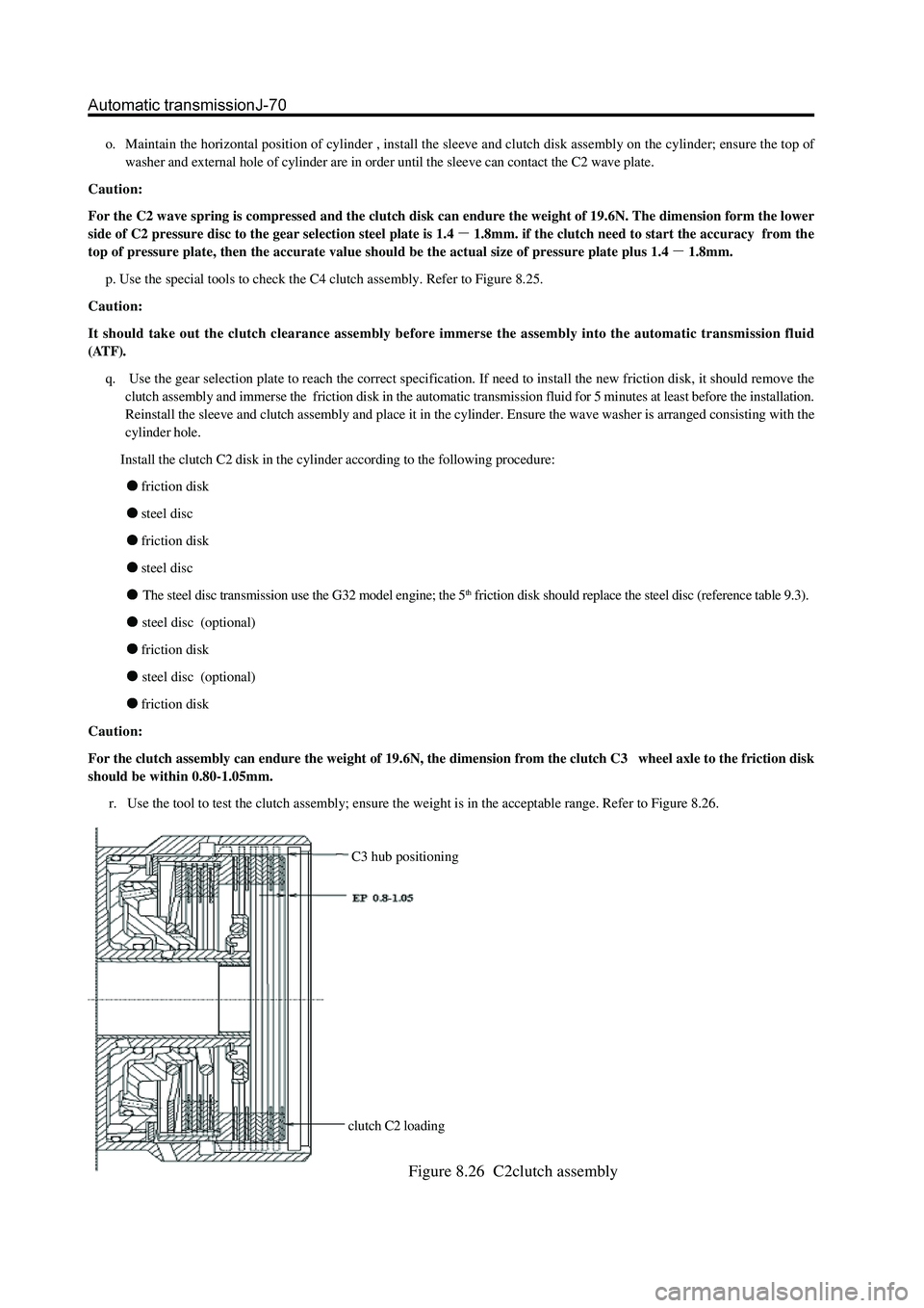
For the clutch assembly can endure the weight of 19.6N, the dimension from the clutch C3 wheel axle to the friction disk
should be within 0.80-1.05mm.
r. Use the tool to test the clutch assembly; ensure the weight is in the acceptable range. Refer to Figure 8.26.
C3 hub positioning
clutch C2 loading
Figure 8.26 C2clutch assembly
Page 147 of 425
v. Install the thrust disc on the cylinder internal wheel axle. Refer to Figure 8.24and 8.19.
w. Connect the C2 /clutch C4 wheel axle assembly in clutch C4 disc, install the clutch C2 disc. Install the C3 wheel axle and
reinforce it by ring spring; ensure the ring spring is installed in the groove fixedly. Please refer to Figure 8.24.
10. Clutch C3 and reverse central gear system
The assembly procedure of clutch C3 and reverse central gear assembly (refer to Figure 8.28) is shown as follows:
Check the cleanness of hole on cylinder. Caution:
It should take out the clutch clearance assembly before immerse the assembly into the automatic transmission fluid
(ATF).
s. Use the gear selection plate to reach the correct specification. It should remove the clutch assembly and immerse the friction
disk in the automatic transmission fluid for 5 minutes at least before the installation if install the new friction disks. Lubricate
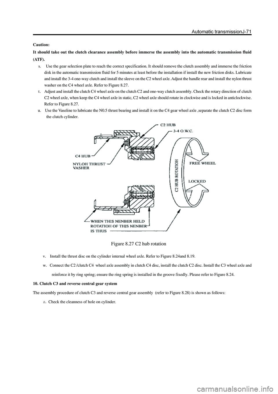
and install the 3-4 one-way clutch and install the sleeve on the C2 wheel axle. Adjust the handle rear and install the nylon thrust
washer on the C4 wheel axle. Refer to Figure 8.27.
t . Adjust and install the clutch C4 wheel axle on the clutch C2 and one-way clutch assembly. Check the rotary direction of clutch
C2 wheel axle, when keep the C4 wheel axle in static, C2 wheel axle should rotate in clockwise and is locked in anticlockwise.
Refer to Figure 8.27.
u. Use the Vaseline to lubricate the N0.5 thrust bearing and install it on the C4 gear wheel axle ,separate the clutch C2 disc form
the clutch cylinder.
Figure 8.27 C2 hub rotation