2006 GREAT WALL HOVER drain bolt
[x] Cancel search: drain boltPage 35 of 425

Clutch-5
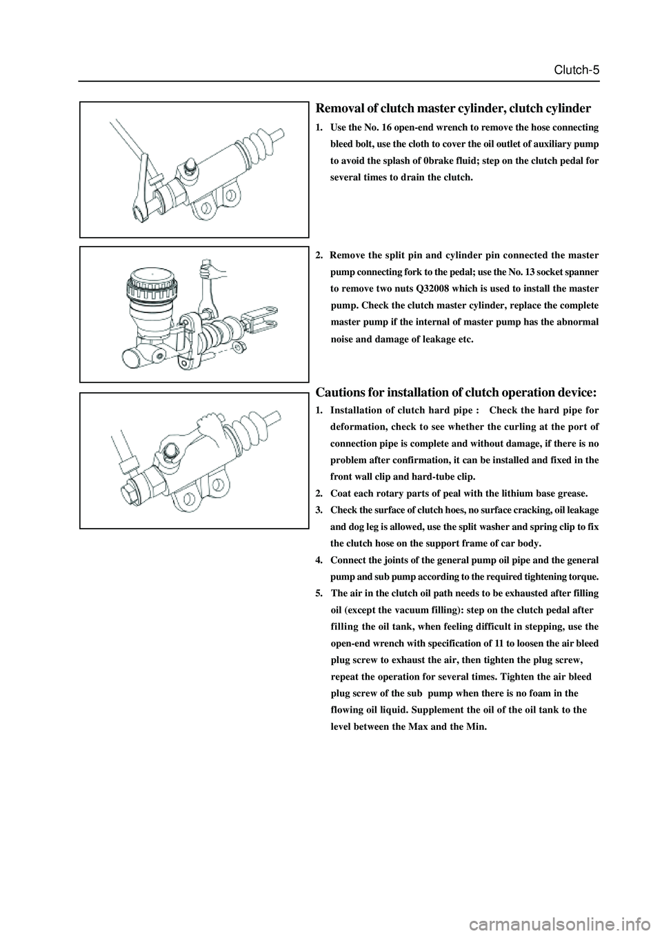
Removal of clutch master cylinder, clutch cylinder
1. Use the No. 16 open-end wrench to remove the hose connecting
bleed bolt, use the cloth to cover the oil outlet of auxiliary pump
to avoid the splash of 0brake fluid; step on the clutch pedal for
several times to drain the clutch.
Cautions for installation of clutch operation device:
1. Installation of clutch hard pipe : Check the hard pipe for
deformation, check to see whether the curling at the port of
connection pipe is complete and without damage, if there is no
problem after confirmation, it can be installed and fixed in the
front wall clip and hard-tube clip.
2. Coat each rotary parts of peal with the lithium base grease.
3. Check the surface of clutch hoes, no surface cracking, oil leakage
and dog leg is allowed, use the split washer and spring clip to fix
the clutch hose on the support frame of car body.
4. Connect the joints of the general pump oil pipe and the general
2. Remove the split pin and cylinder pin connected the master
pump connecting fork to the pedal; use the No. 13 socket spanner
to remove two nuts Q32008 which is used to install the master
pump. Check the clutch master cylinder, replace the complete
master pump if the internal of master pump has the abnormal
noise and damage of leakage etc.
pump and sub pump according to the required tightening torque.
5. The air in the clutch oil path needs to be exhausted after filling
oil (except the vacuum filling): step on the clutch pedal after
fillingthe oil tank, when feeling difficult in stepping, use the
open-end wrench with specification of 11 to loosen the air bleed
plug screw to exhaust the air, then tighten the plug screw,
repeat the operation for several times. Tighten the air bleed
plug screw of the sub pump when there is no foam in the
flowing oil liquid. Supplement the oil of the oil tank to the
level between the Max and the Min.
Page 43 of 425

Inspection of SC5M2D-C transmission:
1.Check the oil level of transmission:
Screw off the oil discharge plug of the transmission; discharge all lubri-
cate oil; screw on the oil discharge plug to the specified torque; the
torque is: 30
35Nm. Fill the transmission with the transmission
oil through the oil filling port, oil number is hyperbolic gear oil SAE80W/
90, which meet API GL-4, oil capacity are 2.2L. Tighten the oil-filling
plug to the specified torque of 30
35Nm. (for area with high or
low temperature refer to the maintenance specification)
2. Replacement of oil seal of rear hosing:
The replacement of the oil seal of rear housing is shown in figure.
Disconnect the drive shaft from the rear housing; remove the oil seal
by the flat screwdriver, then use the special tools to knock the rear
housing oil seal in the rear housing. It should pay attention to the
installation of oil seal, shown as figure. Coat the lip of oil seal with the
specified transmission oil.
3. Removal, installation and inspection of transmission
The preoperation before removal and after installation of transmission
is: Remove and install the manipulator cover assembly, drain and fill
the transmission oil accordance with the regulation; after remove and
install the drive shaft. Separate each plug-in part from the vehicle
transmission .
4
Inspection of manipulator cover assembly
Shown as figure, remove the adhesive on the surface before installation,
use the screwdriver( M8
1.25) to clean the adhesive in the screw
hole; coat the installed part of bolt screw with the specified screw
adhesive. Firstly, install two positioning bolts A, then install other
two bolt A and bolt C respectively. The tightening torque of all bolts is
15
22Nm.
oil filling screw plug (SC1701005)
oil-drain screw-plug assembly (JK721701071)
rear housing oil seal
bolt C(SC-1704003)bolt A(SC-1704004)
Page 64 of 425

Transmission-25
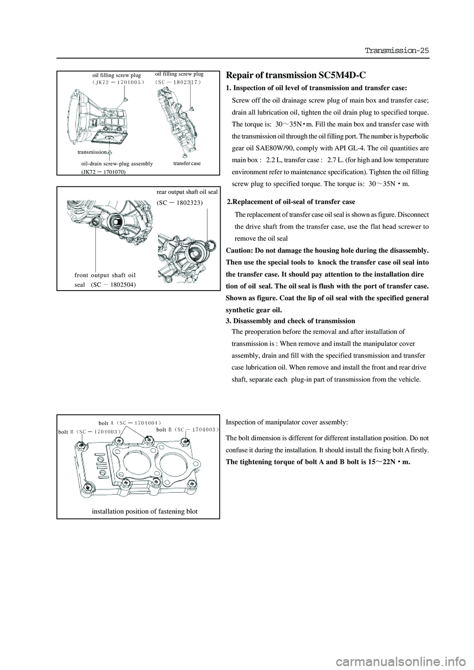
2.Replacement of oil-seal of transfer case
The replacement of transfer case oil seal is shown as figure. Disconnect
the drive shaft from the transfer case, use the flat head screwer to
remove the oil seal
Caution: Do not damage the housing hole during the disassembly.
Then use the special tools to knock the transfer case oil seal into
the transfer case. It should pay attention to the installation dire
tion of oil seal. The oil seal is flush with the port of transfer case.
Shown as figure. Coat the lip of oil seal with the specified general
synthetic gear oil.
3. Disassembly and check of transmission
The preoperation before the removal and after installation of
transmission is : When remove and install the manipulator cover
assembly, drain and fill with the specified transmission and transfer
case lubrication oil. When remove and install the front and rear drive
shaft, separate each plug-in part of transmission from the vehicle.
Inspection of manipulator cover assembly:
The bolt dimension is different for different installation position. Do not
confuse it during the installation. It should install the fixing bolt A firstly.
The tightening torque of bolt A and B bolt is 15
22Nm.
installation position of fastening blot
bolt
bolt bolt
Repair of transmission SC5M4D-C
1. Inspection of oil level of transmission and transfer case:
Screw off the oil drainage screw plug of main box and transfer case;
drain all lubrication oil, tighten the oil drain plug to specified torque.
The torque is: 30
35Nm. Fill the main box and transfer case with
the transmission oil through the oil filling port. The number is hyperbolic
gear oil SAE80W/90, comply with API GL-4. The oil quantities are
main box : 2.2 L, transfer case : 2.7 L. (for high and low temperature
environment refer to maintenance specification). Tighten the oil filling
screw plug to specified torque. The torque is: 30
35Nm.
front output shaft oil
seal (SC
1802504)
rear output shaft oil seal
(SC
1802323)
transmission
transfer case
oil filling screw plug
oil-drain screw-plug assembly
(JK72
1701070) oil filling screw plug
Page 131 of 425

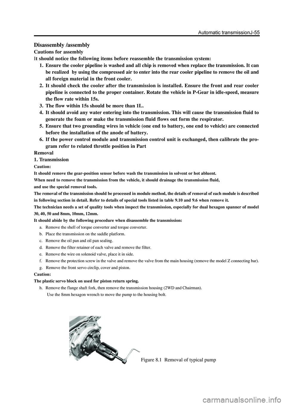
Figure 8.1 Removal of typical pump
Disassembly /assembly
Cautions for assembly
It should notice the following items before reassemble the transmission system:
1. Ensure the cooler pipeline is washed and all chip is removed when replace the transmission. It can
be realized by using the compressed air to enter into the rear cooler pipeline to remove the oil and
all foreign material in the front cooler.
2. It should check the cooler after the transmission is installed. Ensure the front and rear cooler
pipeline is connected to the proper container. Rotate the vehicle in P-Gear in idle-speed, measure
the flow rate within 15s.
3. The flow within 15s should be more than 1L.
4. It should avoid any water entering into the transmission. This will cause the transmission fluid to
generate the foam or make the transmission fluid flows out form the respirator.
5. Ensure that two grounding wires in vehicle (one end to battery, one end to vehicle) are connected
before the installation of the anode of battery.
6. If the power control module and transmission control unit is exchanged, then calibrate the pro-
gram refer to related throttle position in Part
Removal
1. Transmission
Caution:
It should remove the gear-position sensor before wash the transmission in solvent or hot abluent.
When need to remove the transmission from the vehicle, it should drainage the transmission fluid,
and use the special removal tools.
The removal of the transmission should be processed in module method, the details of removal of each module is described
in following section in detail. Refer to details of special tools listed in table 9.10 and 9.6 when remove it.
The technician needs a set of quality tools when inspect the transmission, especially for dual hexagon spanner of model
30, 40, 50 and 8mm, 10mm, 12mm.
It should abide by the following procedure when disassemble the transmission:
a. Remove the shell of torque converter and torque converter.
b. Place the transmission on the saddle platform.
c. Remove the oil pan and oil pan sealing.
d. Remove the filter retainer of each valve and remove the filter.
e. Remove the wire on solenoid valve, place it in side.
f. Remove the protection screw in the valve and remove the valve from the main housing (remove the model Z connecting bar).
g. Remove the front servo circlip, cover and piston.
Caution:
The plastic servo block on used for piston return spring.
h. Remove the flange shaft fork, then remove the transmission housing (2WD and Chairman).
Use the 8mm hexagon wrench to move the pump to the housing bolt.
Page 225 of 425

1. Place the car in the middle of repair platform or
trench, support the front of the car steadily(support
on the carriage) then remove the left and right
front wheel. (make the car in 2WD status before
the disassembly)
2. Remove the beam on the lower of front drive axle
assembly.
3. Disconnect the connection of front drive axle
flange and drive shaft and make the assembly
mark
4. Drain the lubrication oil in reducer.
bolt
front hub cover
circlip
adjusting washer set
flange
disconnect three ports in this position
N m: specified torque
Page 238 of 425

11Rivet the drive gear nut after meet the previ-
ous requirements.
12
Install the reducer assembly on the front drive
axle assembly and assemble the front drive shaft
assembly (refer to Assembly of Front Reducer Assembly
and Assembly of Front Drive Shaft Assembly)
13
Install the oil drain plug; screw off the oil
filling plug and filled with the hypoid gear oil.
Tightening force of oil drain plug: 30-35Nm
Model of lubrication oil: GL-5
Filling amount: Flush to the lower edge of oil filling open
14Insert the oil filling plug washer and tighten
the oil filling plug to the specified torque.
Specified torque : 140-150Nm
15Install the front drive axle assembly on the
carriage.
16
Connect the drive shaft to the flange
a. Align the assembly mark; use four bolts and nuts to connect
the flange of drive shaft and front drive axle.
b.Tighten the nut to the specified torque.
specified torque:
Remarks: Keep the clean of the field during the maintenance.
Page 240 of 425

6. Use the wrench to screw off the bolt on the vent tube
bracket, which is used to fix the vent tube connector.
7. Disconnect the connection between the front drive
shaft assembly and steering knuckle front hub
assembly.
a. Screw off the connecting bolt which is used to fix the front
hub cover; remove the front hub cover.
b. Use the circlip pliers to remove the circlip from the front drive
shaft and remove the adjusting washer.
c. Remove the steering knuckle of both sides and separate it
form the front drive shaft assembly.
1. Support the front of the car; remove two front
wheels and the beam under the front reducer
assembly.
2. Drain the lubrication oil in the front reducer
assembly.
3. Remove the flange of front reducer assembly from
the drive shaft
Caution: Make the assembly mark on the flange of
front reducer assembly and drive shaft before discon-
nect them.
4. Disconnect the connector of power wire of electric
clutch
5. Disconnect three rubber connectors on the front
drive axle vent tube connector assembly.
assembly mark
disconnect three connectors in this place
Page 263 of 425

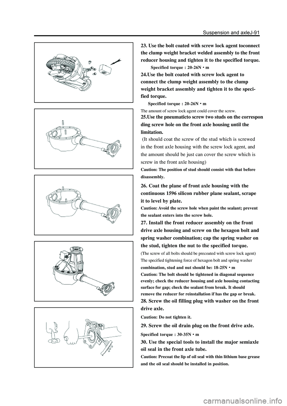
23. Use the bolt coated with screw lock agent toconnect
the clump weight bracket welded assembly to the front
reducer housing and tighten it to the specified torque.
Specified torque : 20-26Nm
24.Use the bolt coated with screw lock agent to
connect the clump weight assembly to the clump
weight bracket assembly and tighten it to the speci-
fied torque.
Specified torque : 20-26Nm
The amount of screw lock agent could cover the screw.
25.Use the pneumaticto screw two studs on the correspon
ding screw hole on the front axle housing until the
limitation.
26. Coat the plane of front axle housing with the
continuous 1596 silicon rubber plane sealant, scrape
it to level by plate.
Caution: Avoid the screw hole when paint the sealant; prevent
the sealant enters into the screw hole.
27. Install the front reducer assembly on the front
drive axle housing and screw on the hexagon bolt and
spring washer combination; cap the spring washer on
the stud, tighten the nut to the specified torque.
(The screw of all bolts should be precoated with screw lock agent)
The specified tightening force of hexagon bolt and spring washer
combination, stud and nut should be: 18-25N
m
Caution: The bolt should be tightened in diagonal sequence
evenly; check the reducer housing and axle housing contacting
surface for gap; check the sealant from break. It should
remove the reducer for reinstallation if has the gap or break.
28. Screw the oil filling plug with washer on the front
drive axle.
Caution: Do not tighten it.
29. Screw the oil drain plug on the front drive axle.
Specified torque : 30-35Nm
30. Use the special tools to install the major semiaxle
oil seal in the front axle tube.
Caution: Precoat the lip of oil seal with thin lithium base grease
and the oil seal should be installed in position.
(It should coat the screw of the stud which is screwed
in the front axle housing with the screw lock agent, and
the amount should be just can cover the screw which is
screw in the front axle housing)
Caution: The position of stud should consist with that before
disassembly.