1993 DODGE TRUCK oil type
[x] Cancel search: oil typePage 1140 of 1502
•
IN-VEHICLE
SERVICE-32RH/36RH/37RH/42RH/46RH
21 - 139 (7) Push solenoid connector out of case.
(8) Remove valve body attaching screws.
(9) Lower valve body enough to remove accumula
tor piston and piston spring (Fig. 24).
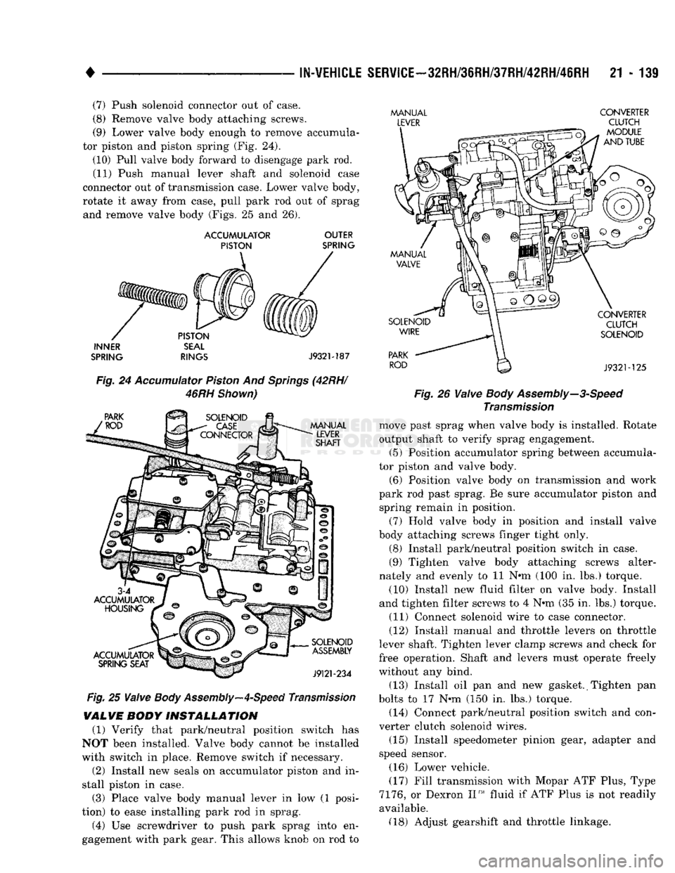
(10) Pull valve body forward to disengage park rod. (11) Push manual lever shaft and solenoid case
connector out of transmission case. Lower valve body,
rotate it away from case, pull park rod out of sprag and remove valve body (Figs. 25 and 26).
ACCUMULATOR
OUTER
PISTON
SPRING
INNER
SEAL
SPRING
RINGS
J932M87
Fig.
24
Accumulator
Piston
And
Springs
(42RH/
46RH
Shown)
Fig.
25
Valve
Body
Assembly—4-Speed
Transmission
VALVE
BODY
INSTALLATION
(1) Verify that park/neutral position switch has
NOT been installed. Valve body cannot be installed
with switch in place. Remove switch if necessary.
(2) Install new seals on accumulator piston and in
stall piston in case.
(3) Place valve body manual lever in low (1 posi
tion) to ease installing park rod in sprag.
(4) Use screwdriver to push park sprag into en
gagement with park gear. This allows knob on rod to
MANUAL
CONVERTER
LEVER
CLUTCH
- Fig. 26
Valve
Body
Assembly—3-Speed
Transmission
move past sprag when valve body is installed. Rotate
output shaft to verify sprag engagement. (5) Position accumulator spring between accumula
tor piston and valve body.
(6) Position valve body on transmission and work
park rod past sprag. Be sure accumulator piston and spring remain in position.
(7) Hold valve body in position and install valve
body attaching screws linger tight only.
(8) Install park/neutral position switch in case.
(9) Tighten valve body attaching screws alter
nately and evenly to 11 N#m (100 in. lbs.) torque.
(10) Install new fluid filter on valve body. Install
and tighten filter screws to 4 N-m (35 in. lbs.) torque. (11) Connect solenoid wire to case connector.
(12) Install manual and throttle levers on throttle
lever shaft. Tighten lever clamp screws and check for
free operation. Shaft and levers must operate freely
without any bind.
(13) Install oil pan and new gasket. (Tighten pan
bolts to 17 N»m (150 in. lbs.) torque. (14) Connect park/neutral position switch and con
verter clutch solenoid wires.
(15) Install speedometer pinion gear, adapter and
speed sensor.
(16) Lower vehicle.
(17) Fill transmission with Mopar ATF Plus, Type
7176,
or Dexron II™ fluid if ATF Plus is not readily
available. (18) Adjust gearshift and throttle linkage.
Page 1151 of 1502
21 - 150
AUTOMATIC TRANSMISSION REMOVAL
AND
INSTALLATION
• (3) Remove transmission oil pan, remove gasket,
drain oil and reinstall pan. (4) If overdrive unit had malfunctioned, or if fluid
is contaminated, remove entire transmission. If diag
nosis indicated overdrive clutch or governor problems
only, remove overdrive unit only.
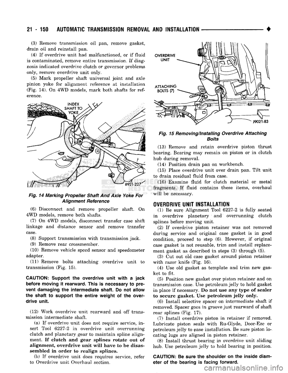
(5) Mark propeller shaft universal joint and axle
pinion yoke for alignment reference at installation (Fig. 14). On 4WD models, mark both shafts for
ref
erence.
Fig.
14 Marking Propeller Shaft And Axle Yoke For
Alignment
Reference
(6) Disconnect and remove propeller shaft. On
4WD models, remove both shafts.
(7) On 4WD models, disconnect transfer case shift
linkage and distance sensor and remove transfer
case.
(8) Support transmission with transmission jack.
(9) Remove rear crossmember.
(10) Remove vehicle speed sensor and speedometer
adapter.
(11) Remove bolts attaching overdrive unit to
transmission (Fig. 15).
CAUTION:
Support
the
overdrive unit with
a
jack before moving
it
rearward. This
is
necessary
to
pre
vent damaging
the
intermediate shaft.
Do not
allow
the shaft
to
support
the
entire
weight
of the
over drive unit.
(12) Work overdrive unit rearward and off trans
mission intermediate shaft.
(a) If overdrive unit does not require service, in
sert Tool 6227-2 in overdrive unit overrunning
clutch and planetary gear to maintain spline align
ment. If clutch and gear splines rotate out of
alignment, overdrive unit will have to be disas
sembled in order to realign splines.
(b) If overdrive unit does requires service, refer
to Overdrive unit Overhaul section.
Fig.
15 Removing/Installing Overdrive Attaching
Bolts
(13) Remove and retain overdrive piston thrust
bearing. Bearing may remain on piston or in clutch hub during removal.
(14) Position drain pan on workbench.
(15) Place overdrive unit over drain pan. Tilt unit
to drain residual fluid from case. (16) Examine fluid for clutch material or metal
fragments. If fluid contains these items, overhaul
will be necessary.
OVERDRIVE
UNIT INSTALLATION
(1) Be sure Alignment Tool 6227-2 is fully seated
in overdrive planetary and overrunning clutch
splines before moving unit.
(2) If overdrive piston retainer was not removed
during service and original case gasket is in good
condition, proceed to step (6). However, if original case gasket is not reusable, trim and install replace
ment gasket as described in steps (3) through (5).
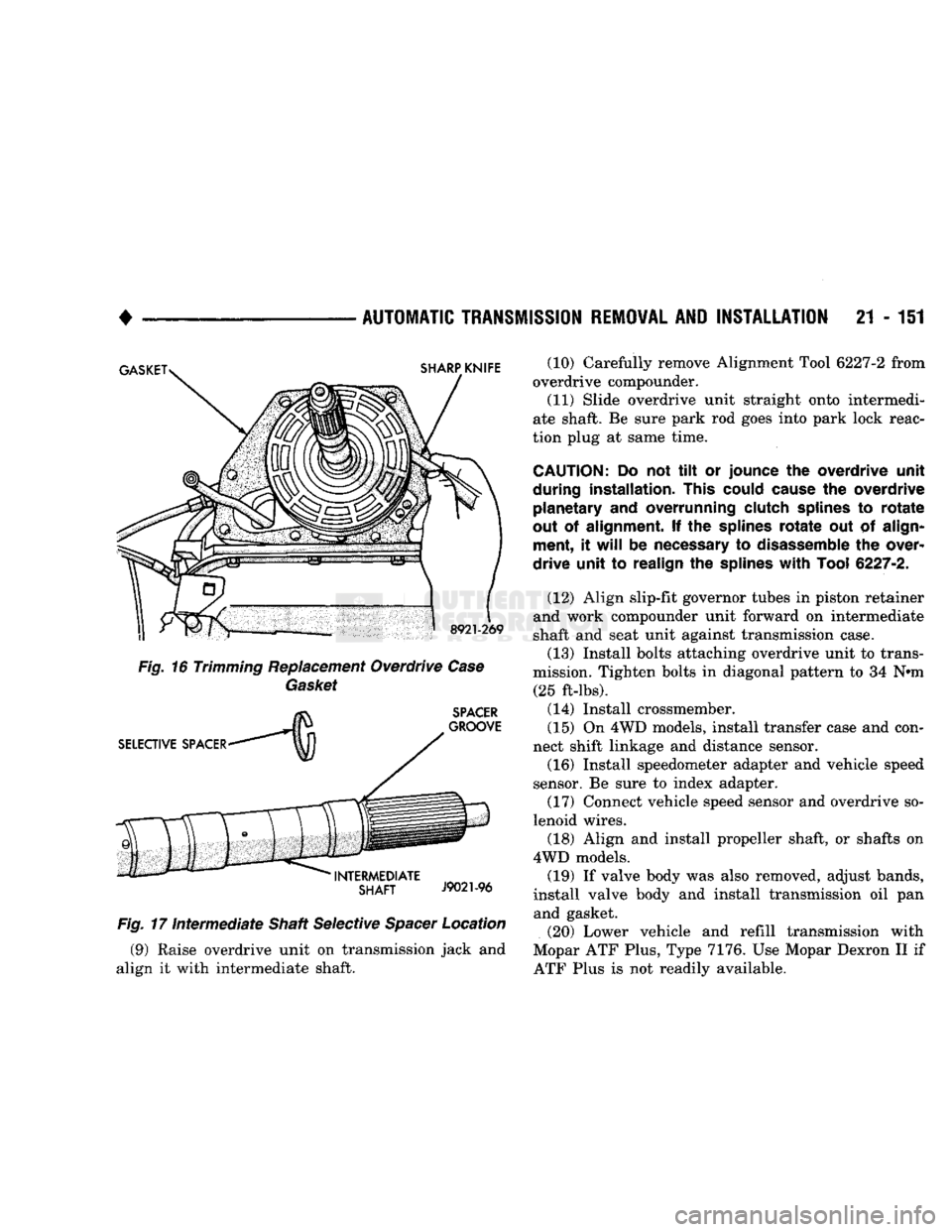
(3) Cut out old case gasket around piston retainer
with razor knife (Fig. 16). (4) Use old gasket as template and trim new gas
ket to fit. (5) Position new gasket over piston retainer and on
transmission case. Use petroleum jelly to hold gasket in place if necessary. Do not use any type of sealer
to secure gasket. Use petroleum jelly only. (6) Install selective spacer on intermediate shaft if
removed. Spacer goes in groove just rearward of shaft
rear splines (Fig. 17). (7) Install overdrive piston in retainer if removed.
Lubricate piston seals with Ru-Glyde, Door-Eze or
petroleum jelly to ease installation. Be sure piston lo
cating lugs are aligned in piston retainer. (8) Install thrust bearing in overdrive unit sliding
hub.
Use petroleum jelly to hold bearing in position.
CAUTION:
Be
sure
the
shoulder
on the
inside diam
eter
of the
bearing
is
facing forward.
Page 1152 of 1502
•
AUTOMATIC
TRANSMISSION
REMOVAL
AND
INSTALLATION
21 - 151
Fig.
17
Intermediate
Shaft Selective
Spacer
Location (9) Raise overdrive unit on transmission jack and
align it with intermediate shaft. (10) Carefully remove Alignment Tool 6227-2 from
overdrive compounder.
(11) Slide overdrive unit straight onto intermedi
ate shaft. Be sure park rod goes into park lock reac
tion plug at same time.
CAUTION:
Do not tilt or
jounce
the
overdrive unit
during installation. This could cause
the
overdrive planetary
and
overrunning clutch splines
to
rotate
out
of
alignment.
If the
splines
rotate
out of
align ment,
it
will
be
necessary
to
disassemble
the
over
drive unit
to
realign
the
splines
with
Tool
6227-2.
(12) Align slip-fit governor tubes in piston retainer
and work compounder unit forward on intermediate
shaft and seat unit against transmission case.
(13) Install bolts attaching overdrive unit to trans
mission. Tighten bolts in diagonal pattern to 34 N»m (25 ft-lbs).
(14) Install crossmember.
(15) On 4WD models, install transfer case and con
nect shift linkage and distance sensor. (16) Install speedometer adapter and vehicle speed
sensor. Be sure to index adapter.
(17) Connect vehicle speed sensor and overdrive so
lenoid wires.
(18) Align and install propeller shaft, or shafts on
4WD models. (19) If valve body was also removed, adjust bands,
install valve body and install transmission oil pan and gasket.
(20) Lower vehicle and refill transmission with
Mopar ATF Plus, Type 7176. Use Mopar Dexron II if
ATF Plus is not readily available.
Page 1153 of 1502
21
- 152
TRANSMISSION OVERHAUL—32RH
•
TRANSMISSION
OWERHAUL—32RH
INDEX
page
Extension Housing
and
Park Lock Component Overhaul
............................ 160
Front
Clutch Overhaul
165
Front
Servo
and
Band Overhaul
175
Governor
and
Park Gear Overhaul
160
Oil Pump
and
Reaction Shaft Support Overhaul
. 162
Overhaul Service
Information
158
Overrunning CIutch—Low-Reverse Drum—Rear
TRANSMISSION
DISASSEMBLY
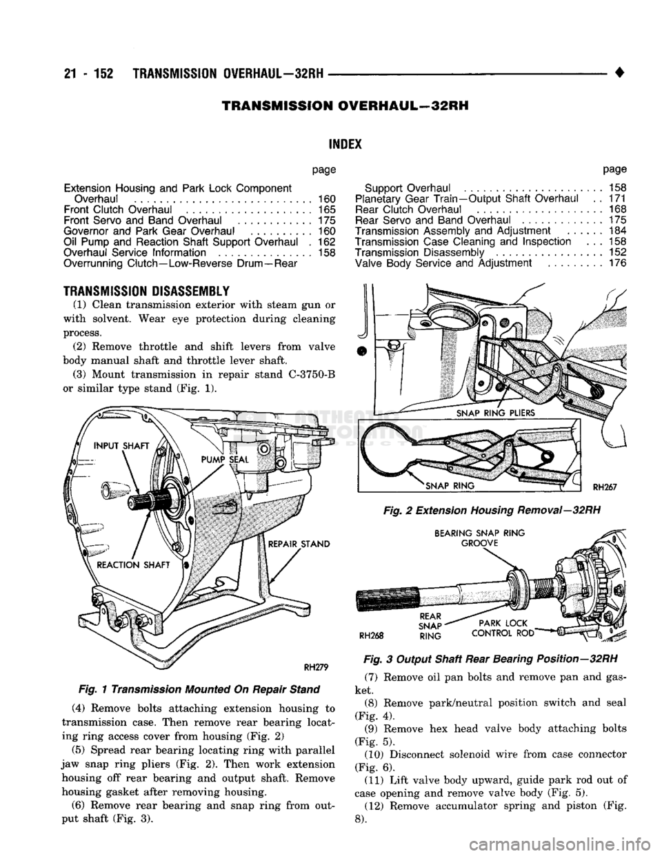
(1) Clean transmission exterior with steam gun or
with solvent. Wear eye protection during cleaning
process. (2) Remove throttle and shift levers from valve
body manual shaft and throttle lever shaft. (3) Mount transmission in repair stand C-3750-B
or similar type stand (Fig. 1).
Fig.
1
Transmission
Mounted
On Repair
Stand
(4)
Remove bolts attaching extension housing to
transmission case. Then remove rear bearing locat
ing ring access cover from housing (Fig. 2)
(5) Spread rear bearing locating ring with parallel
jaw snap ring pliers (Fig. 2). Then work extension housing off rear bearing and output shaft. Remove
housing gasket after removing housing.
(6)
Remove rear bearing and snap ring from out
put shaft (Fig. 3).
page
Support Overhaul
158
Planetary Gear
Train-Output
Shaft Overhaul
. . 171
Rear
Clutch Overhaul
168
Rear
Servo
and
Band Overhaul
............. 175
Transmission Assembly
and
Adjustment
...... 184
Transmission
Case
Cleaning
and
Inspection
... 158
Transmission Disassembly
152
Valve Body Service
and
Adjustment
......... 176
Fig.
2 Extension
Housing
Removal—32RH
Fig.
3 Output Shaft Rear Bearing Position—32RH (7) Remove oil pan bolts and remove pan and gas
ket. (8) Remove park/neutral position switch and seal
(Fig. 4). (9) Remove hex head valve body attaching bolts
(Fig. 5). (10) Disconnect solenoid wire from case connector
(Fig. 6). (11) Lift valve body upward, guide park rod out of
case opening and remove valve body (Fig. 5). (12) Remove accumulator spring and piston (Fig.
8).
Page 1159 of 1502
21 - 158
TRANSMISSION
OVERHAUL—32RH
•
OVERHAUL SERVICE
INFORMATION
Inspect all the transmission bushings during over
haul. Bushing condition is important as worn, scored
bushings contribute to low pressures, clutch slip and accelerated wear of other components. Do not replace
bushings as a matter of course. Replace bushings
only when actually worn or scored. Use recommended tools to replace bushings. The
tools are sized and designed to remove, install and seat bushings correctly, The bushing replacement
tools are included in Bushing Tool Set C-3887-B. The
tool set is manufactured by the Miller Tool Co. and is available through the dealer tool program. Pre-sized service bushings are available for re
placement purposes. Only the sun gear bushings are
not serviced. Low cost of the sun gear assembly
makes it easier to simply replace the gear and bush
ings as an assembly. Heli-Coil inserts are recommended for repairing
damaged, stripped or worn threads in aluminum
parts.
These inserts are available from most automo
tive jobbers. Stainless steel inserts are preferred. The use of crocus cloth is permissible where neces
sary, providing it is used carefully. When used on
valves, use extreme care to avoid rounding off sharp
edges.
Sharp edges are vital as they prevent foreign
matter from getting between the valve and valve
bore.
Do not reuse oil seals, gaskets, seal rings, or
O-rings during overhaul. Replace these parts as a
matter of course. Also do not reuse snap rings or
E-clips that are bent or distorted. Replace these parts as well.
Lubricate transmission parts with Mopar ATF
Plus,
Type 7176, or Dexron II™ transmission fluid during overhaul and assembly.
Use Ru-Glyde or Door Eze to lubricate clutch pis
ton seals. Use petroleum jelly to lubricate O-rings and thrust washers. Petroleum jelly can also be used
to hold parts in place during reassembly.
TRANSMISSION
CASE
CLEAN1N8
AND
INSPECTION
Clean the case in a solvent tank. Flush the case
bores and fluid passages thoroughly with solvent. Dry the case and all fluid passages with compressed
air. Be sure all solvent is removed from the case and
that all fluid passages are clear. Do not use shop towels or rags to dry the case
(or any other transmission component) unless
they are made from lint-free materials. Lint will
readily adhere to case surfaces and transmission
components and will circulate throughout the
transmission after assembly. A sufficient quan
tity of lint can block fluid passages and interfere
with valve body operation. Inspect the case for cracks, porous spots, worn
bores,
or damaged threads. Damaged threads can be repaired with Helicoil thread inserts. However, the
case will have to be replaced if it exhibits any type of
damage or wear.
Lubricate the front band adjusting screw threads
with petroleum jelly and thread the screw part-way into the case. Be sure the screw turns freely.
Remount the case in Repair Stand C-3750-B after
cleaning and inspection.
OVERRUNNING CLUTCH-LOW-REVERSE
DRUM-REAR
SUPPORT OVERHAUL
DISASSEMBLING OVERRUNNING CLUTCH/ LOW-REVERSE DRUM
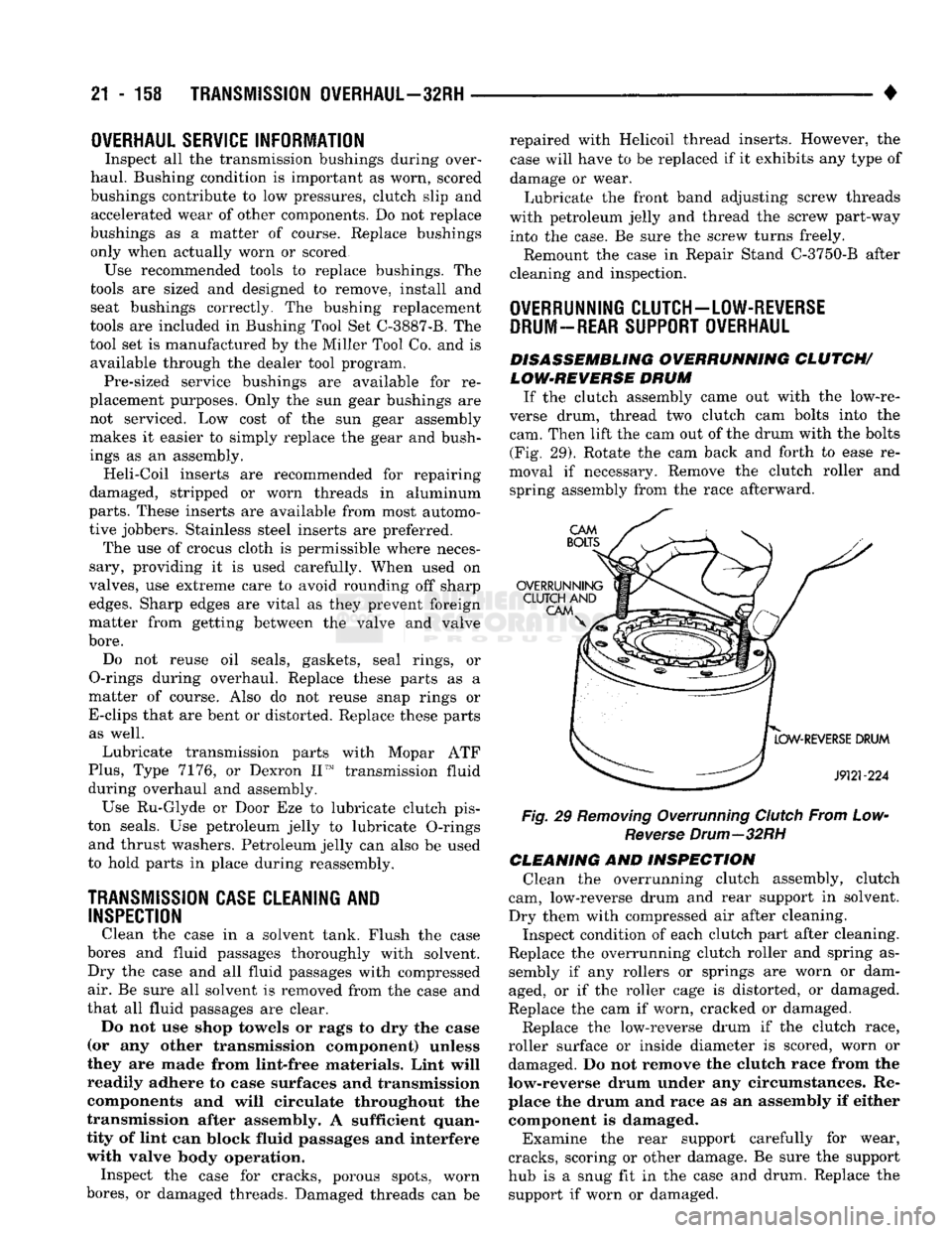
If the clutch assembly came out with the low-re
verse drum, thread two clutch cam bolts into the cam. Then lift the cam out of the drum with the bolts (Fig. 29). Rotate the cam back and forth to ease re
moval if necessary. Remove the clutch roller and spring assembly from the race afterward.
Fig, 29 Removing Overrunning Clutch From Low- Reverse Drum—32RH
CLEANING AND INSPECTION Clean the overrunning clutch assembly, clutch
cam, low-reverse drum and rear support in solvent.
Dry them with compressed air after cleaning. Inspect condition of each clutch part after cleaning.
Replace the overrunning clutch roller and spring as sembly if any rollers or springs are worn or dam
aged, or if the roller cage is distorted, or damaged.
Replace the cam if worn, cracked or damaged.
Replace the low-reverse drum if the clutch race,
roller surface or inside diameter is scored, worn or damaged. Do not remove the clutch race from the
low-reverse drum under any circumstances. Re place the drum and race as an assembly if either component is damaged.
Examine the rear support carefully for wear,
cracks, scoring or other damage. Be sure the support
hub is a snug fit in the case and drum. Replace the support if worn or damaged.
Page 1162 of 1502
•
J9121-47
Fig.
37 Correct Position Of
Sprag
And
Spring—32RH
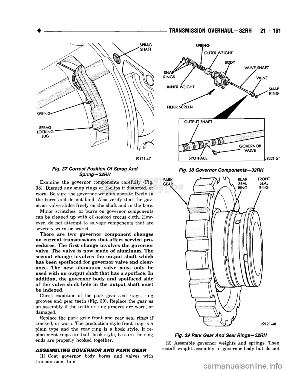
Examine the governor components carefully (Fig.
38). Discard any snap rings or E-clips if distorted, or
worn. Be sure the governor weights operate freely in the bores and do not bind. Also verify that the gov
ernor valve slides freely on the shaft and in the bore.
Minor scratches, or burrs on governor components
can be cleaned up with oil-soaked crocus cloth. How ever, do not attempt to salvage components that are
severely worn or scored. There are two governor component changes
on current transmissions that affect service pro
cedures. The first change involves the governor
valve. The valve is now made of aluminum. The second change involves the output shaft which
has been spotfaced for governor valve end clear ance. The new aluminum valve must only be
used with an output shaft that has a spotface. In addition, the governor body and spotfaced side
of the valve shaft hole in the output shaft must
be indexed.
Check condition of the park gear seal rings, ring
grooves and gear teeth (Fig. 39). Replace the gear as an assembly if the teeth or ring grooves are worn, or
damaged.
Replace the park gear front and rear seal rings if
cracked, or worn. The production style front ring is a
plain type and the rear ring is a hook style. If re
placement rings are both hook-style, be sure the ring ends are properly hooked together.
ASSEMBLING
GOVERNOR
AND
PARK GEAR
(1) Coat governor body bores and valves with
transmission fluid.
TRANSMISSION
OVERHAUL—32RH
21 - 161
Fig.
39
Park
Gear And
Seal
Rings—32RH
(2) Assemble governor weights and springs. Then
install weight assembly in governor body but do not
Page 1181 of 1502
21
- 180
TRANSMISSION OVERHAUL—32RH
•
REGULATOR VALVE
THROTTLE
PRESSURE
PLUG REGULATOR
VALVE
SPRING
SLEEVE
LINE
PRESSURE
PLUG
REGULATOR VALVE END
PLATE
SHIFT
VALVE END PLATE
2-3 SHIFT
VALVE
AND
SPRING
J912M80
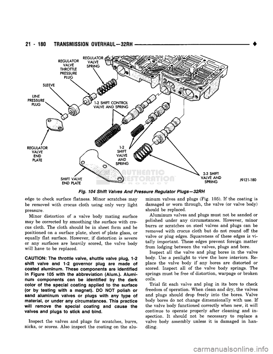
Fig. 104 Shift Valves And Pressure Regulator Plugs—32RH
edge to check surface flatness. Minor scratches may
be removed with crocus cloth using only very light pressure.
Minor distortion of a valve body mating surface
may be corrected by smoothing the surface with cro
cus cloth. The cloth should be in sheet form and be
positioned on a surface plate, sheet of plate glass, or equally flat surface. However, if distortion is severe
or any surfaces are heavily scored, the valve body
will have to be replaced.
CAUTION:
The
throttle
valve, shuttle valve plug,
1-2
shift valve
and 1-2
governor plug
are
made
of
coated
aluminum.
These
components are
identified
in Figure
105
with
the
abbreviation (Alum.). Alumi
num components
can be
identified
by the
dark
color
of the
special coating applied
to the
surface
(or
by
testing
with
a
magnet).
DO NOT
polish
or
sand
aluminum valves
or
plugs
with
any
type
of
material,
or
under
any
circumstances. This practice
will
remove the special
coating
and
cause
the
valves
and
plugs
to
stick
and
bind.
Inspect the valves and plugs for scratches, burrs,
nicks,
or scores. Also inspect the coating on the alu minum valves and plugs (Fig. 105). If the coating is
damaged or worn through, the valve (or valve body)
should be replaced. Aluminum valves and plugs must not be sanded or
polished under any circumstances. However, minor
burrs or scratches on steel valves and plugs can be removed with crocus cloth but do not round off the
valve or plug edges. Squareness of these edges is vi
tally important. These edges prevent foreign matter from lodging between the valves, plugs and bore.
Inspect all the valve and plug bores in the valve
body. Use a penlight to view the bore interiors. Re place the valve body if any bores are distorted or scored. Inspect all of the valve body springs. The
springs must be free of distortion, warpage or broken
coils.
Trial fit each valve and plug in its bore to check
freedom of operation. When clean and dry, the valves and plugs should drop freely into the bores. Valve
body bores do not change dimensionally with use. If the valve body functioned correctly when new, it will
continue to operate properly after cleaning and inspection. It should not be necessary to replace a
valve body assembly unless it is damaged in handling.
Page 1203 of 1502
21
- 202
TRANSMISSION
OVERHAUL—36RH/37RH
•
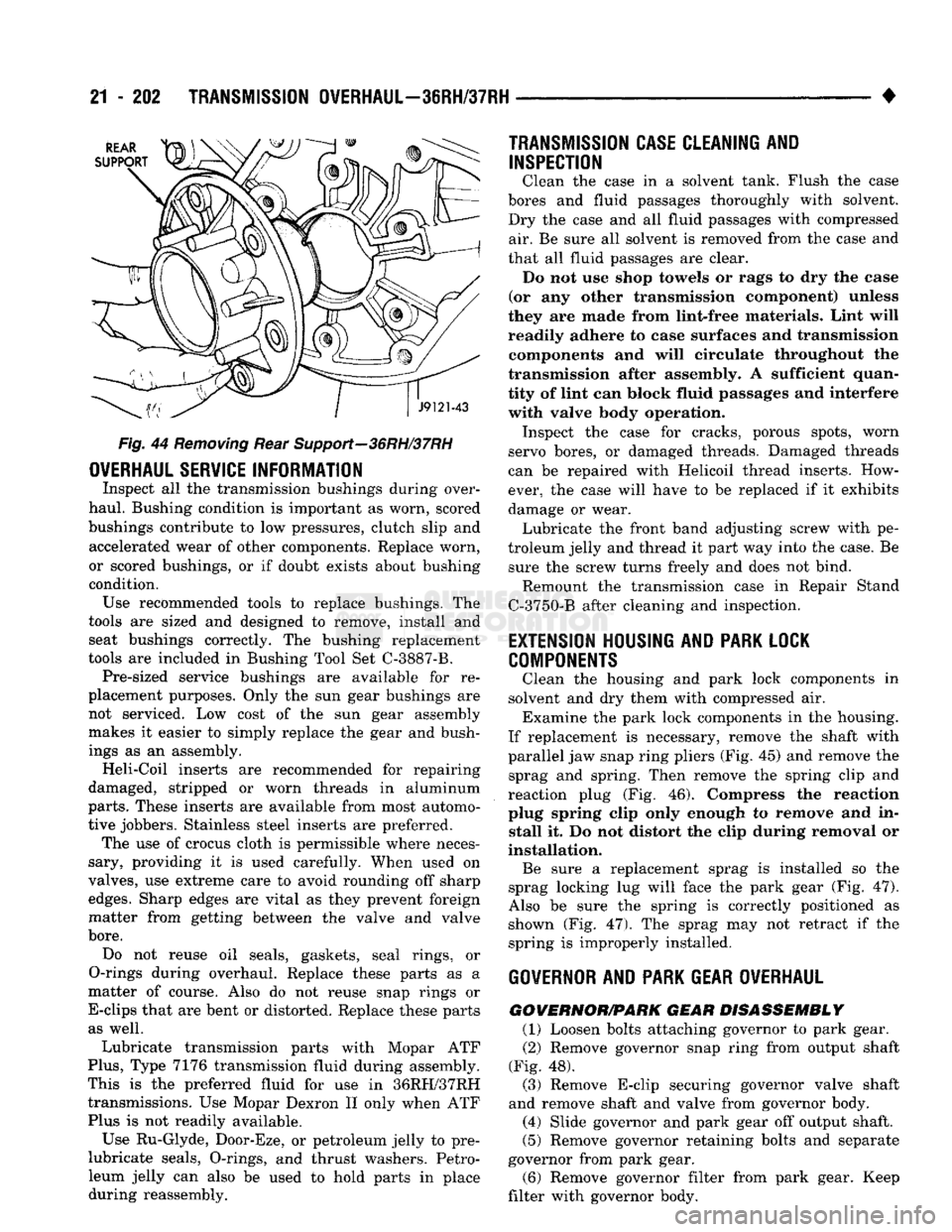
Fig.
44
Removing
Rear Support—36RH/37RH
OVERHAUL
SERVICE
INFORMATION
Inspect
all the
transmission bushings during over
haul. Bushing condition
is
important
as
worn, scored
bushings contribute
to low
pressures, clutch slip
and
accelerated wear
of
other components. Replace worn,
or scored bushings,
or if
doubt exists about bushing
condition. Use recommended tools
to
replace bushings.
The
tools
are
sized
and
designed
to
remove, install
and
seat bushings correctly.
The
bushing replacement
tools
are
included
in
Bushing Tool
Set
C-3887-B. Pre-sized service bushings
are
available
for re
placement purposes. Only
the sun
gear bushings
are
not serviced.
Low
cost
of the sun
gear assembly
makes
it
easier
to
simply replace
the
gear
and
bush
ings
as an
assembly. Heli-Coil inserts
are
recommended
for
repairing
damaged, stripped
or
worn threads
in
aluminum
parts.
These inserts
are
available from most automo
tive jobbers. Stainless steel inserts
are
preferred. The
use of
crocus cloth
is
permissible where neces
sary, providing
it is
used carefully. When used
on
valves,
use
extreme care
to
avoid rounding
off
sharp
edges.
Sharp edges
are
vital
as
they prevent foreign
matter from getting between
the
valve
and
valve
bore.
Do
not
reuse
oil
seals, gaskets, seal rings,
or
O-rings during overhaul. Replace these parts
as a
matter
of
course. Also
do not
reuse snap rings
or
E-clips that
are
bent
or
distorted. Replace these parts as well.
Lubricate transmission parts with Mopar
ATF
Plus,
Type
7176
transmission fluid during assembly.
This
is the
preferred fluid
for use in
36RH/37RH transmissions.
Use
Mopar Dexron
II
only when
ATF
Plus
is not
readily available.
Use Ru-Glyde, Door-Eze,
or
petroleum jelly
to pre-
lubricate seals, O-rings,
and
thrust washers. Petro
leum jelly
can
also
be
used
to
hold parts
in
place during reassembly.
TRANSMISSION CASE
CLEAN1NI
AND
INSPECTION
Clean
the
case
in a
solvent tank. Flush
the
case
bores
and
fluid passages thoroughly with solvent.
Dry
the
case
and all
fluid passages with compressed air.
Be
sure
all
solvent
is
removed from
the
case
and
that
all
fluid passages
are
clear. Do
not use
shop towels
or
rags
to dry the
ease
(or
any
other transmission component) unless
they
are
made from lint-free materials. Lint will
readily adhere
to
case surfaces
and
transmission components
and
will circulate throughout
the
transmission after assembly.
A
sufficient quan
tity
of
lint
can
block fluid passages
and
interfere with valve body operation. Inspect
the
case
for
cracks, porous spots, worn
servo bores,
or
damaged threads. Damaged threads
can
be
repaired with Helicoil thread inserts. How
ever,
the
case will have
to be
replaced
if it
exhibits
damage
or
wear. Lubricate
the
front band adjusting screw with
pe
troleum jelly
and
thread
it
part
way
into
the
case.
Be
sure
the
screw turns freely
and
does
not
bind. Remount
the
transmission case
in
Repair Stand
C-3750-B after cleaning
and
inspection.
EXTENSION
HOUSING
AND PARK
LOCK
COMPONENTS
Clean
the
housing
and
park lock components
in
solvent
and dry
them with compressed
air.
Examine
the
park lock components
in the
housing.
If replacement
is
necessary, remove
the
shaft with
parallel
jaw
snap ring pliers
(Fig. 45) and
remove
the
sprag
and
spring. Then remove
the
spring clip
and
reaction plug
(Fig. 46).
Compress
the
reaction
plug spring clip only enough
to
remove
and in
stall
it. Do not
distort
the
clip during removal
or
installation. Be sure
a
replacement sprag
is
installed
so the
sprag locking
lug
will face
the
park gear
(Fig. 47).
Also
be
sure
the
spring
is
correctly positioned
as
shown
(Fig. 47). The
sprag
may not
retract
if the
spring
is
improperly installed.
GOVERNOR
AND PARK
GEAR OVERHAUL
GOWERNOR/PARK
GEAR DISASSEMBLY
(1) Loosen bolts attaching governor
to
park gear.
(2) Remove governor snap ring from output shaft
(Fig.
48).
(3) Remove E-clip securing governor valve shaft
and remove shaft
and
valve from governor body. (4) Slide governor
and
park gear
off
output shaft.
(5) Remove governor retaining bolts
and
separate
governor from park gear.
(6) Remove governor filter from park gear. Keep
filter with governor body.