1993 DODGE TRUCK oil type
[x] Cancel search: oil typePage 1221 of 1502
21
- 220
TRANSMISSION OVERHAUL—36RH/37RH
•
VALVE
BODY CLEANING AND INSPECTION
The only serviceable valve body components are
the:
• park lock rod and E-clip
• switch valve and spring
• pressure adjusting screw bracket
• throttle valve lever
• manual shaft
• manual shaft seal/washer/E-clip/detent ball
• fluid filter.
The remaining valve body components are serviced
only as part of a complete valve body assembly (Fig.
92).
Clean the valve body components in a parts clean
ing solution only. Do not use gasoline, kerosene, or
any type of caustic solution.
Dry the parts with compressed air. Make sure all
passages are clean and free from obstructions. Do not use rags or shop towels to dry or wipe
off valve body components unless they are made
from lint free material. Lint will adhere to the
valve body components causing valve bind. Lint
can also clog filters and small fluid passages.
Inspect the throttle and manual valve levers and
shafts.
Do not attempt to straighten a bent shaft
or correct a loose lever. Replace these compo
nents if worn, bent, loose or damaged in any way.
Inspect all of the valve body mating surfaces for
scratches, nicks, burrs, or distortion. Use a straight
edge to check surface flatness. Minor scratches may
be removed with crocus cloth using only very light pressure.
Minor distortion of a valve body mating surface
may be corrected by smoothing the surface with cro
cus cloth. Position the crocus cloth sheet on a surface
plate, sheet of plate glass, or equally flat surface. If distortion is severe or any surfaces are heavily
scored, the valve body will have to be replaced.
CAUTION:
The
throttle
valve, shuttle valve plug,
1-2
shift valve
and 1-2
governor plug
are
made
of
coated aluminum. Aluminum components
can be
identified
by the
dark color
of the
special coating
applied
to the
surface
(or by
testing
with
a
magnet).
DO
NOT
polish
or
sand
aluminum valves
or
plugs
with
any
type
of
material,
or
under
any
circum
stances.
This practice
will
remove
the
special coat
ing
and
cause
the
valves
and
plugs
to
stick
and
bind.
Inspect the valves and plugs for scratches, burrs,
nicks,
or scores. Also inspect the coating on the alu
minum valves and plugs. If the coating is damaged
or worn through, the valve (or valve body) should be
replaced.
Aluminum valves and plugs must not be sanded or
polished under any circumstances. However, minor burrs or scratches on steel valves and plugs can be
removed with crocus cloth but do not round off the
valve or plug edges. Squareness of these edges is vi
tally important; they prevent foreign matter from lodging between the valves and plugs and the bore.
Inspect all the valve and plug bores in the valve
body. Use a penlight to view the bore interiors. Re
place the valve body if any bores are distorted or scored. Inspect all of the valve body springs. The
springs must be free of distortion, warpage or broken
coils.
Trial fit each valve and plug in its bore to check
freedom of operation. When clean and dry, the valves and plugs should drop freely into the bores.
Valve body bores do not change dimensionally with
use.
If the valve body functioned correctly when new,
it will continue to operate properly after cleaning and inspection. It should not be necessary to replace a valve body assembly unless it is damaged in han
dling.
VALVE BODY ASSEMBLY
CAUTION:
Do not
force
the
valves
or
plugs
into place during reassembly.
If the
valve body bores
and
the
valves
and
plugs
are
free
of
distortion
or
burrs,
the
valves
and
plugs
should slide into place
easily.
In
addition,
do not
overtighten
the
transfer plate
and
valve body screws during reassembly.
Overtightening
can
distort
the
valve body resulting
in valve sticking,
cross
leakage
and
unsatisfactory
operation. Tighten
the
screws
alternately
and
evenly
to 4 Nnn (35 in.
lbs.) torque only.
(1) Lubricate valve body bores, valves and plugs
with ATF Plus, or Dexron II™ transmission fluid.
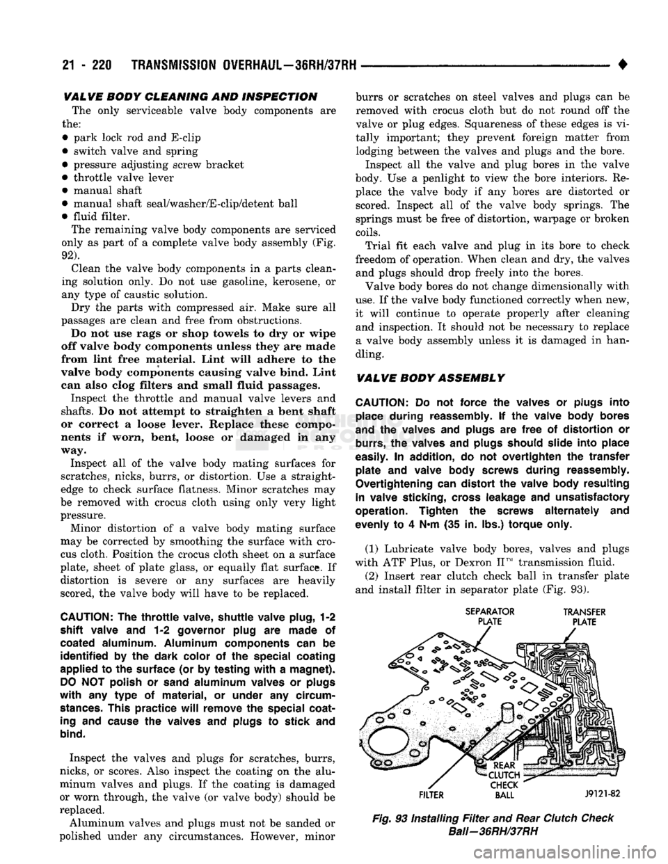
(2) Insert rear clutch check ball in transfer plate
and install filter in separator plate (Fig. 93).
SEPARATOR
TRANSFER
PLATE PLATE
FILTER
BALL
J9121-82
Fig.
93 Installing
Filter
and Rear
Clutch
Check
Bali—36RH/37RH
Page 1225 of 1502
21
- 224
TRANSMISSION
OVERHAUL—36RH/37RH
• Throttle
Pressure
Adjustment
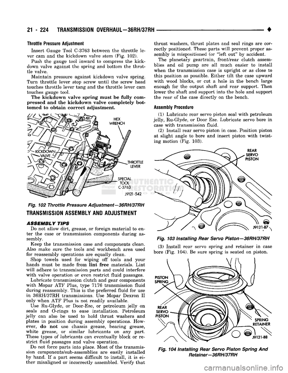
Insert Gauge Tool
C-3763
between the throttle le
ver cam and the kickdown valve stem (Fig. 102).
Push the gauge tool inward to compress the kick-
down valve against the spring and bottom the throt
tle valve. Maintain pressure against kickdown valve spring.
Turn throttle lever stop screw until the screw head
touches throttle lever tang and the throttle lever cam
touches gauge tool. The kickdown valve spring must be fully com
pressed and the kickdown valve completely bot
tomed to obtain correct adjustment.
HEX
WRENCH
THROTTLE
LEVER
SPECIAL
TOOL
C-3763
J9121-542
Fig.
102
Throttle
Pressure
Adjustment—36RH/37RH
TRANSMISSION
ASSEMBLY
AND
ADJUSTMENT
ASSEMBLY
TIPS
Do not allow dirt, grease, or foreign material to en
ter the case or transmission components during as sembly.
Keep the transmission case and components clean.
Also make sure the tools and workbench area used
for reassembly operations are equally clean.
Shop towels used for wiping off tools and your
hands must be made from lint free materials. Lint
will adhere to transmission parts and could interfere
with valve operation or even restrict fluid passages.
Lubricate transmission clutch and gear components
with Mopar ATF Plus, type 7176 transmission fluid
during reassembly. This is the preferred fluid for use in 36RH/37RH transmissions. Use Mopar Dexron II
only when ATF Plus is not readily available.
Use Ru-Glyde, or Door-Eze, or petroleum jelly on
seals and O-rings to ease installation. Petroleum
jelly can also be used to hold thrust washers and plates in position during assembly operations. However, do not use chassis grease, bearing grease,
white grease, or similar lubricants on any part.
These types of lubricants can eventually block or re strict fluid passages and valve operation.
Do not force parts into place. Most of the transmis
sion components/sub-assemblies are easily installed
by hand. If a part seems difficult to install, it is ei ther misaligned or incorrectly assembled. Verify that thrust washers, thrust plates and seal rings are cor
rectly positioned. These parts will prevent proper as
sembly is mispositioned (or "left out" by accident. The planetary geartrain, front/rear clutch assem
blies and oil pump are all much easier to install
when the transmission case is upright or as close to
this position as possible. Either tilt the case upward
with wood blocks, or cut a hole in the bench large enough for the output shaft and rear support. Then lower the shaft and support into the hole and support
the rear of the case directly on the bench.
Assembly
Procedure
(1) Lubricate rear servo piston seal with petroleum
jelly, Ru-Glyde, or Door Eze. Lubricate servo bore in case with transmission fluid. (2) Install rear servo piston in case. Position piston
at slight angle to bore and insert piston with twist
ing motion (Fig. 103).
REAR
SERVO
PISTON
J9121-87>
Fig.
103 Installing Rear
Servo
Piston—36RH/37RH
(3) Install rear servo spring and retainer in case
bore (Fig. 104). Be sure spring is seated on piston.
SPRING
RETAINER
v-'
J9121-88
Fig.
104 Installing Rear
Servo
Piston
Spring
And Retainer-36RH/37RH
Page 1240 of 1502
•
TRANSMISSION
OVERHAUL-42RH
21 - 239
CLUTCH
ASSEMBLY J9121-222
Fig.
29 Overrunning
Clutch
Assembly
Removal—42RH
cercise caution when removing snap ring. Servo
bore can be scratched or nicked if care is not
excercised. (42) Remove compressor tools and remove front
servo rod guide, spring and servo piston.
Fig.
30
Compressing
Front
Servo
Rod
Guide—42RH
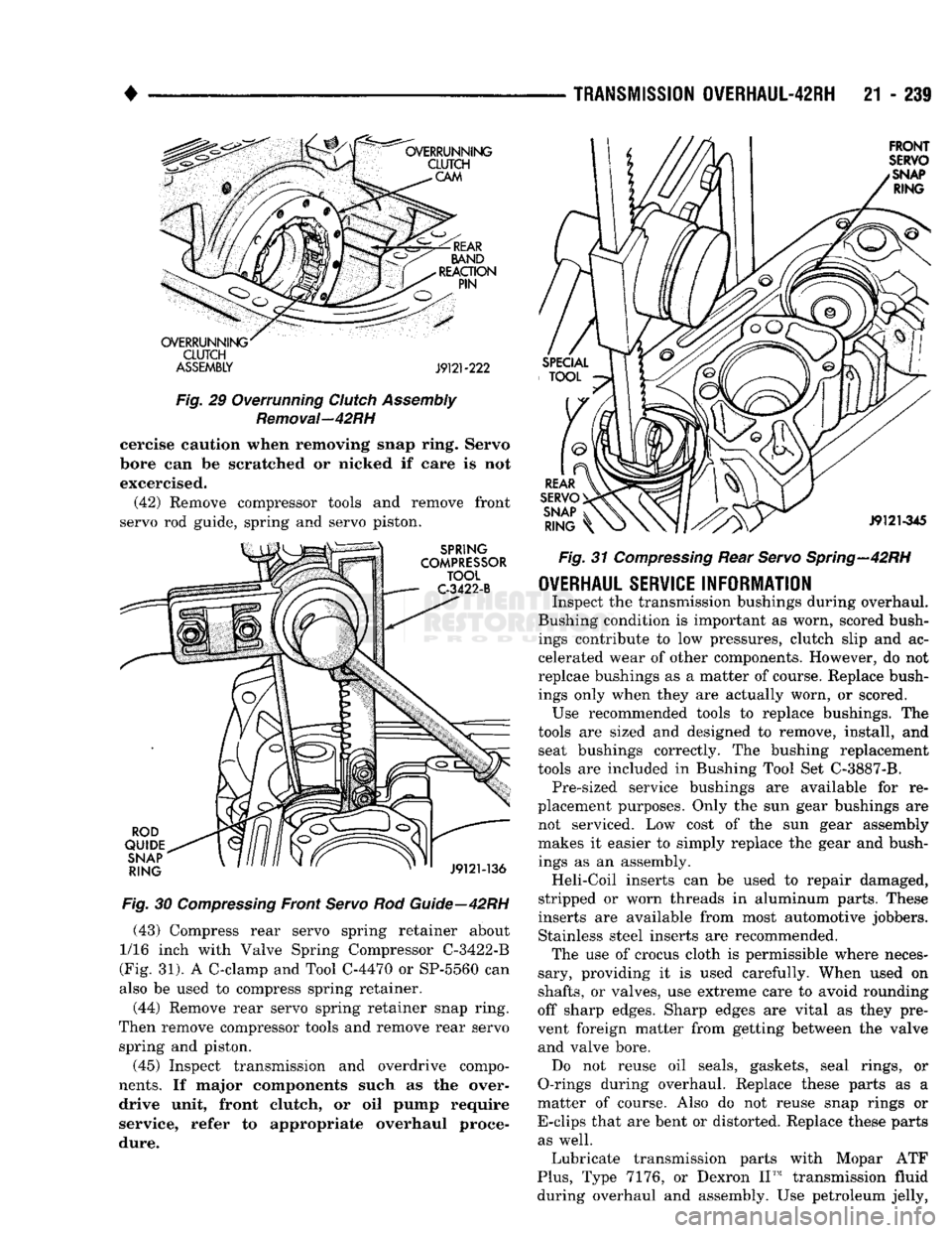
(43) Compress rear servo spring retainer about
1/16 inch with Valve Spring Compressor C-3422-B
(Fig. 31). A C-clamp and Tool C-4470 or SP-5560 can
also be used to compress spring retainer.
(44) Remove rear servo spring retainer snap ring.
Then remove compressor tools and remove rear servo spring and piston.
(45) Inspect transmission and overdrive compo
nents.
If major components such as the over drive unit, front clutch, or oil pump require
service, refer to appropriate overhaul proce
dure.
Fig.
31
Compressing
Rear
Servo
Spring—42RH
OVERHAUL
SERVICE
INFORMATION
Inspect the transmission bushings during overhaul.
Bushing condition is important as worn, scored bush ings contribute to low pressures, clutch slip and ac
celerated wear of other components. However, do not
replcae bushings as a matter of course. Replace bush ings only when they are actually worn, or scored. Use recommended tools to replace bushings. The
tools are sized and designed to remove, install, and seat bushings correctly. The bushing replacement
tools are included in Bushing Tool Set C-3887-B. Pre-sized service bushings are available for re
placement purposes. Only the sun gear bushings are
not serviced. Low cost of the sun gear assembly makes it easier to simply replace the gear and bush
ings as an assembly. Heli-Coil inserts can be used to repair damaged,
stripped or worn threads in aluminum parts. These
inserts are available from most automotive jobbers.
Stainless steel inserts are recommended. The use of crocus cloth is permissible where neces
sary, providing it is used carefully. When used on
shafts,
or valves, use extreme care to avoid rounding
off sharp edges. Sharp edges are vital as they pre
vent foreign matter from getting between the valve and valve bore. Do not reuse oil seals, gaskets, seal rings, or
O-rings during overhaul. Replace these parts as a
matter of course. Also do not reuse snap rings or
E-clips that are bent or distorted. Replace these parts as well. Lubricate transmission parts with Mopar ATF
Plus,
Type 7176, or Dexron II™ transmission fluid
during overhaul and assembly. Use petroleum jelly,
Page 1241 of 1502
21 - 240
TRANSMISSION
OVERHAUL-42RH
—
_ . *
J9121-225
Fig. 33 Installing Overrunning Clutch Rollers In Retainer—42RH
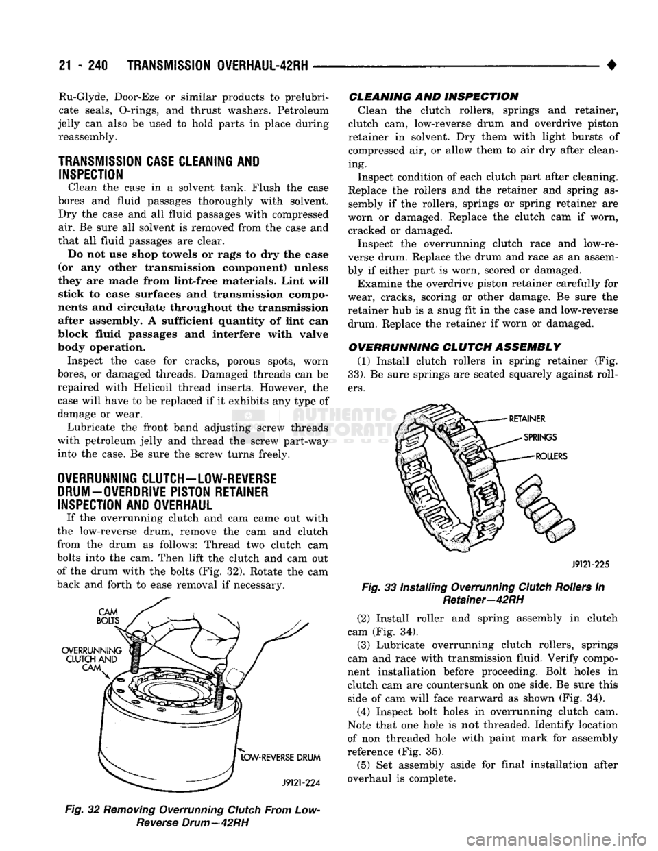
(2) Install roller and spring assembly in clutch
cam (Fig. 34).
(3) Lubricate overrunning clutch rollers, springs
cam and race with transmission fluid. Verify compo
nent installation before proceeding. Bolt holes in
clutch cam are countersunk on one side. Be sure this side of cam will face rearward as shown (Fig. 34).
(4) Inspect bolt holes in overrunning clutch cam.
Note that one hole is not threaded. Identify location
of non threaded hole with paint mark for assembly
reference (Fig. 35).
(5) Set assembly aside for final installation after
overhaul is complete.
Fig.
32
Removing
Overrunning
Clutch
From Low-
Reverse
Drum—42RH
CLEANING
AND
INSPECTION
Clean the clutch rollers, springs and retainer,
clutch cam, low-reverse drum and overdrive piston
retainer in solvent. Dry them with light bursts of compressed air, or allow them to air dry after clean
ing.
Inspect condition of each clutch part after cleaning.
Replace the rollers and the retainer and spring as
sembly if the rollers, springs or spring retainer are
worn or damaged. Replace the clutch cam if worn,
cracked or damaged.
Inspect the overrunning clutch race and low-re
verse drum. Replace the drum and race as an assem
bly if either part is worn, scored or damaged.
Examine the overdrive piston retainer carefully for
wear, cracks, scoring or other damage. Be sure the
retainer hub is a snug fit in the case and low-reverse
drum. Replace the retainer if worn or damaged.
OVERRUNNING CLUTCH ASSEMBLY (1) Install clutch rollers in spring retainer (Fig.
33).
Be sure springs are seated squarely against roll
ers.
Ru-Glyde, Door-Eze or similar products to prelubri-
cate seals, O-rings, and thrust washers. Petroleum
jelly can also be used to hold parts in place during reassembly.
TRANSMISSION
CASE
CLEANING
AND
INSPECTION
Clean the case in a solvent tank. Flush the case
bores and fluid passages thoroughly with solvent. Dry the case and all fluid passages with compressed
air. Be sure all solvent is removed from the case and
that all fluid passages are clear. Do not use shop towels or rags to dry the case
(or any other transmission component) unless
they are made from lint-free materials. Lint will stick to case surfaces and transmission compo
nents and circulate throughout the transmission after assembly. A sufficient quantity of lint can
block fluid passages and interfere with valve
body operation. Inspect the case for cracks, porous spots, worn
bores,
or damaged threads. Damaged threads can be
repaired with Helicoil thread inserts. However, the
case will have to be replaced if it exhibits any type of
damage or wear. Lubricate the front band adjusting screw threads
with petroleum jelly and thread the screw part-way into the case. Be sure the screw turns freely.
OVERRUNNING CLUTCH-LOW-REVERSE DRUM-OVERDRIVE PISTON RETAINER
INSPECTION
AND
OVERHAUL
If the overrunning clutch and cam came out with
the low-reverse drum, remove the cam and clutch
from the drum as follows: Thread two clutch cam
bolts into the cam. Then lift the clutch and cam out of the drum with the bolts (Fig. 32). Rotate the cam
back and forth to ease removal if necessary.
Page 1270 of 1502
•
TRANSMISSION
OVERHAUL-42RH
21 - 269 must be performed properly and in the correct se
quence. Line pressure is adjusted first and throttle
pressure is adjusted last.
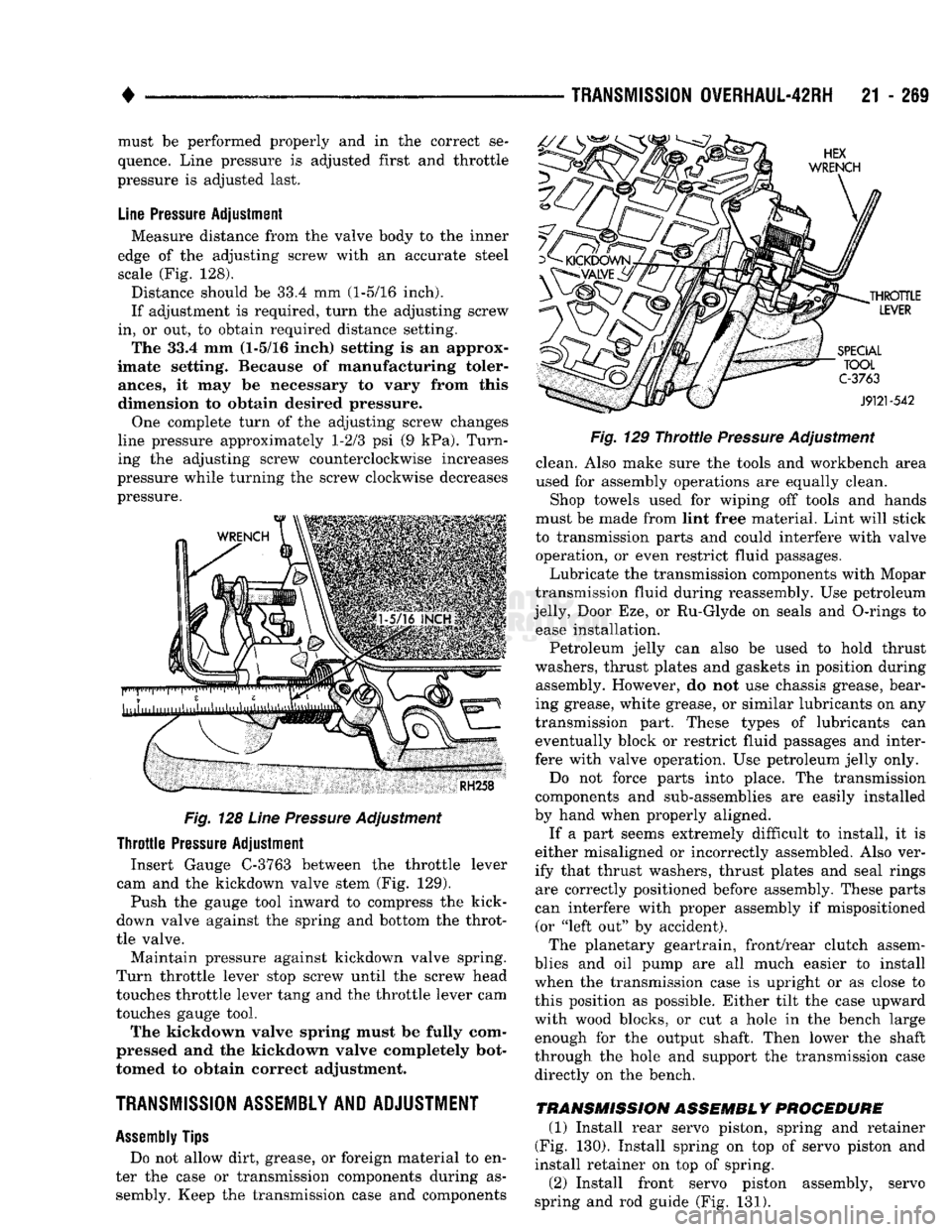
Line
Pressure
Adjustment
Measure distance from the valve body to the inner
edge of the adjusting screw with an accurate steel
scale (Fig. 128).
Distance should be 33.4 mm (1-5/16 inch).
If adjustment is required, turn the adjusting screw
in, or out, to obtain required distance setting. The 33.4 mm (1-5/16 inch) setting is an approx
imate setting. Because of manufacturing toler
ances,
it may be necessary to vary from this
dimension to obtain desired pressure.
One complete turn of the adjusting screw changes
line pressure approximately 1-2/3 psi (9 kPa). Turn
ing the adjusting screw counterclockwise increases
pressure while turning the screw clockwise decreases
pressure.
Fig.
128
Line
Pressure
Adjustment
Throttle
Pressure
Adjustment Insert Gauge C-3763 between the throttle lever
cam and the kickdown valve stem (Fig. 129).
Push the gauge tool inward to compress the kick-
down valve against the spring and bottom the throt
tle valve.
Maintain pressure against kickdown valve spring.
Turn throttle lever stop screw until the screw head
touches throttle lever tang and the throttle lever cam
touches gauge tool.
The kickdown valve spring must be fully com
pressed and the kickdown valve completely bot
tomed to obtain correct adjustment.
TRANSMISSION ASSEMBLY AND ADJUSTMENT
Assembly
Tips
Do not allow dirt, grease, or foreign material to en
ter the case or transmission components during as sembly. Keep the transmission case and components
Fig.
129
Throttie
Pressure
Adjustment
clean. Also make sure the tools and workbench area
used for assembly operations are equally clean.
Shop towels used for wiping off tools and hands
must be made from lint free material. Lint will stick
to transmission parts and could interfere with valve operation, or even restrict fluid passages.
Lubricate the transmission components with Mopar
transmission fluid during reassembly. Use petroleum
jelly, Door Eze, or Ru-Glyde on seals and O-rings to ease installation.
Petroleum jelly can also be used to hold thrust
washers, thrust plates and gaskets in position during assembly. However, do not use chassis grease, bear
ing grease, white grease, or similar lubricants on any
transmission part. These types of lubricants can eventually block or restrict fluid passages and inter
fere with valve operation. Use petroleum jelly only.
Do not force parts into place. The transmission
components and sub-assemblies are easily installed
by hand when properly aligned.
If a part seems extremely difficult to install, it is
either misaligned or incorrectly assembled. Also ver
ify that thrust washers, thrust plates and seal rings are correctly positioned before assembly. These parts
can interfere with proper assembly if mispositioned (or "left out" by accident).
The planetary geartrain, front/rear clutch assem
blies and oil pump are all much easier to install
when the transmission case is upright or as close to
this position as possible. Either tilt the case upward
with wood blocks, or cut a hole in the bench large enough for the output shaft. Then lower the shaft
through the hole and support the transmission case
directly on the bench.
TRANSMISSION ASSEMBLY PROCEDURE
(1) Install rear servo piston, spring and retainer
(Fig. 130). Install spring on top of servo piston and
install retainer on top of spring.
(2) Install front servo piston assembly, servo
spring and rod guide (Fig. 131).
Page 1286 of 1502
•
TRANSMISSION
OVERHAUL-46RH
21 - 285 ercise caution when removing snap ring. Servo
bore can be scratched or nicked if care is not
exercised.
(39)
Remove tools and remove servo piston and
spring.
(40)
Compress rear servo piston with C-clamp and
Tool C-4470, or Valve Spring Compressor C-3422-B (Fig. 36). Compress servo spring retainer only
enough to permit snap ring removal.
(41) Remove servo piston snap ring (Fig. 36). Start
one end of ring out of bore. Then carefully work re
moval tool around back of snap ring until free of ring
groove. Exercise caution when removing snap
ring. Servo bore can be scratched or nicked if care is not exercised.
(42) Remove tools and remove rear servo retainer,
spring and piston assembly.
Fig.
36
Removing
Rear
Servo
Retaining
Snap
Ring—46RH
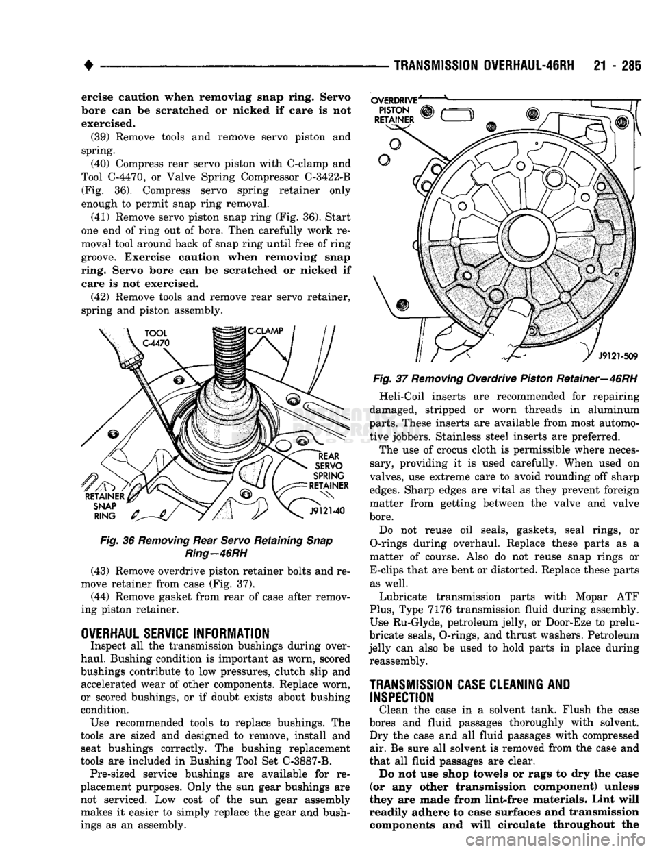
(43) Remove overdrive piston retainer bolts and re
move retainer from case (Fig. 37).
(44) Remove gasket from rear of case after remov
ing piston retainer.
OVERHAUL SERVICE
INFORMATION
Inspect all the transmission bushings during over
haul. Bushing condition is important as worn, scored
bushings contribute to low pressures, clutch slip and accelerated wear of other components. Replace worn,
or scored bushings, or if doubt exists about bushing
condition. Use recommended tools to replace bushings. The
tools are sized and designed to remove, install and seat bushings correctly. The bushing replacement
tools are included in Bushing Tool Set C-3887-B. Pre-sized service bushings are available for re
placement purposes. Only the sun gear bushings are not serviced. Low cost of the sun gear assembly makes it easier to simply replace the gear and bushings as an assembly.
Fig.
37
Removing
Overdrive
Piston
Retainer—46RH
Heli-Coil inserts are recommended for repairing
damaged, stripped or worn threads in aluminum
parts.
These inserts are available from most automo
tive jobbers. Stainless steel inserts are preferred.
The use of crocus cloth is permissible where neces
sary, providing it is used carefully. When used on
valves, use extreme care to avoid rounding off sharp
edges.
Sharp edges are vital as they prevent foreign
matter from getting between the valve and valve
bore.
Do not reuse oil seals, gaskets, seal rings, or
O-rings during overhaul. Replace these parts as a
matter of course. Also do not reuse snap rings or
E-clips that are bent or distorted. Replace these parts as well.
Lubricate transmission parts with Mopar ATF
Plus,
Type 7176 transmission fluid during assembly.
Use Ru-Glyde, petroleum jelly, or Door-Eze to prelu-
bricate seals, O-rings, and thrust washers. Petroleum
jelly can also be used to hold parts in place during reassembly.
TRANSMISSION
CASE
CLEANING
AND
INSPECTION
Clean the case in a solvent tank. Flush the case
bores and fluid passages thoroughly with solvent. Dry the case and all fluid passages with compressed air. Be sure all solvent is removed from the case and
that all fluid passages are clear. Do not use shop towels or rags to dry the case
(or any other transmission component) unless
they are made from lint-free materials. Lint will readily adhere to case surfaces and transmission components and will circulate throughout the
Page 1287 of 1502
21 - 286
TRANSMISSION OVERHAUL-46RH
• transmission after assembly. A sufficient quan
tity of lint can block fluid passages and Interfere
with valve body operation.
Inspect the case for cracks, porous spots, worn
servo bores, or damaged threads. Damaged threads
can be repaired with Helicoil thread inserts. How
ever, the case will have to be replaced if it exhibits
damage or wear.
Lubricate the front band adjusting screw and lock-
nut with petroleum jelly and thread it part way into
the case. Be sure the screw turns freely and does not
bind. Install the locknut on the screw after checking screw thread operation.
OVERDRIVE PISTON AND RETAINER SERVICE
Remove and discard the piston seals.
Clean the piston and retainer in parts cleaning sol
vent. Do not use any type of caustic materials for
cleaning. Such materials may etch the surfaces caus
ing damage. Inspect the piston and retainer carefully. Replace
either part if cracked, porous or damaged in any way. Check condition of the locating lugs on the pis
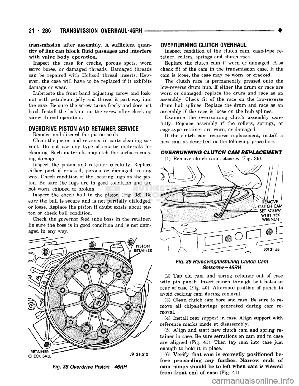
ton. Be sure the lugs are in good condition and are not worn, chipped or broken. Inspect the check ball in the piston (Fig. 38). Be
sure the ball is secure and is not partially dislodged,
or loose. Replace the piston if doubt exists about pis
ton or check ball condition. Check the governor feed tube boss in the retainer.
Be sure the boss is in good condition and is not dam aged in any way.
Fig.
38 Overdrive
Piston—46RH
OWERRUNNlNG CLUTCH OVERHAUL
Inspect condition of the clutch cam, cage-type re
tainer, rollers, springs and clutch race. Replace the clutch cam if worn or damaged. Also
check fit of the cam in the transmission case. If the
cam is loose, the case may be worn, or cracked. The clutch race is permanently pressed onto the
low-reverse drum hub. If either the drum or race are
worn or damaged, replace the drum and race as an assembly. Check fit of the race on the low-reverse
drum hub splines. Replace the drum and race as an assembly if the race is loose on the hub splines. Examine the overrunning clutch assembly care
fully. Replace assembly if the rollers, springs, or cage-type retainer are worn, or damaged. If the clutch cam requires replacement, install a
new cam as described in the following procedure.
OVERRUNNING CLUTCH CAM REPLACEMENT (1) Remove clutch cam setscrew (Fig. 39).
Fig.
39 Removing/Installing
Clutch
Cam
Setscrew—46RH
(2)
Tap old cam and spring retainer out of case
with pin punch. Insert punch through bolt holes at rear of case (Fig. 40). Alternate position of punch to avoid cocking cam during removal.
(3) Clean clutch cam bore and case. Be sure to re
move all chips/shavings generated during cam re moval.
(4) Install rear support in case. Align support with
reference marks made at disassembly. (5) Align and start new clutch cam and spring re
tainer in case. Be sure serrations on cam and in case are aligned (Fig. 41). Then tap cam into case just
enough to hold it in place.
(6) Verify that cam is correctly positioned be
fore proceeding any further. Narrow ends of
cam ramps should be to left when cam is viewed
from front end of case (Fig. 41).
Page 1310 of 1502
TRANSMISSION
0VERHAUL-4IRH
21 - 309
LOWER HOUSING
3-4
SHUTTLE
3-4
ACCUMULATOR PISTON
3-4
ACCUMULATOR HOUSING
3-4
SHUTTLE VALVE
THROTTLE PLUG
TIMING VALVE
COVER
3-4 SHIFT
VALVE AND
SPRING
SPRING
RETAINER
CONVERTER CLUTCH TIMING VALVE AND SPRING
CONVERTER CLUTCH
SOLENOID SOLENOID
GASKET
OVERDRIVE
SEPARATOR
PLATE
J932M58
3^4 ACCUMULATOR
HOUSING
ACCUMULATOR PISTON
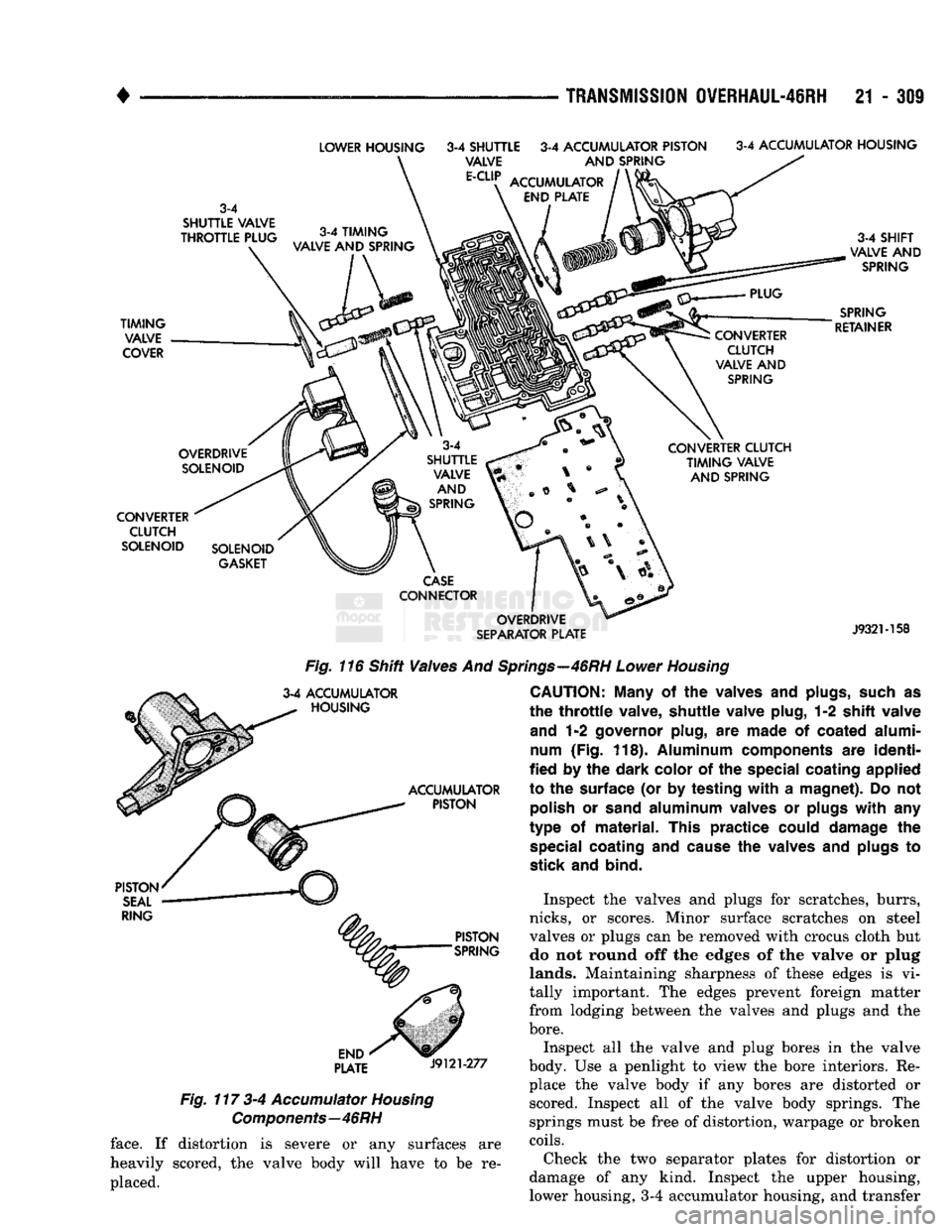
Fig.
116 Shift Valves
And
Springs—46RH
Lower
Housing
CAUTION: Many
of the
valves
and
plugs, such
as
the
throttle
valve,
shuttle
valve
plug,
1-2
shift
valve
and
1-2
governor
plug,
are
made
of
coated
alumi
num
(Fig.
118).
Aluminum
components
are
identi
fied
by the
dark
color
of the
special
coating
applied
to
the
surface
(or by
testing
with
a
magnet).
Do not
polish
or
sand
aluminum
valves
or
plugs
with
any
type
of
material.
This
practice
could
damage
the
special
coating
and
cause
the
valves
and
plugs
to
stick
and
bind. PISTON
SEAL
RING
PISTON
SPRING
END
PLATE
J9121-277
Fig.
117 3-4
Accumulator
Housing
Components—46RH
Inspect
the
valves
and
plugs
for
scratches, burrs,
nicks,
or
scores. Minor surface scratches
on
steel
valves
or
plugs
can be
removed with crocus cloth
but
do
not
round
off the
edges
of the
valve
or
plug
lands.
Maintaining sharpness
of
these edges
is vi
tally important.
The
edges prevent foreign matter from lodging between
the
valves
and
plugs
and the
bore.
Inspect
all the
valve
and
plug bores
in the
valve
body.
Use a
penlight
to
view
the
bore interiors.
Re
place
the
valve body
if any
bores
are
distorted
or
scored. Inspect
all of the
valve body springs.
The
springs must
be
free
of
distortion, warpage
or
broken
coils.
Check
the two
separator plates
for
distortion
or
damage
of any
kind. Inspect
the
upper housing,
lower housing,
3-4
accumulator housing,
and
transfer
face.
If
distortion
is
severe
or any
surfaces
are
heavily scored,
the
valve body will have
to be re
placed.