1993 DODGE TRUCK oil type
[x] Cancel search: oil typePage 885 of 1502
14
- 66
FUEL
SYSTEM
REMOVAL
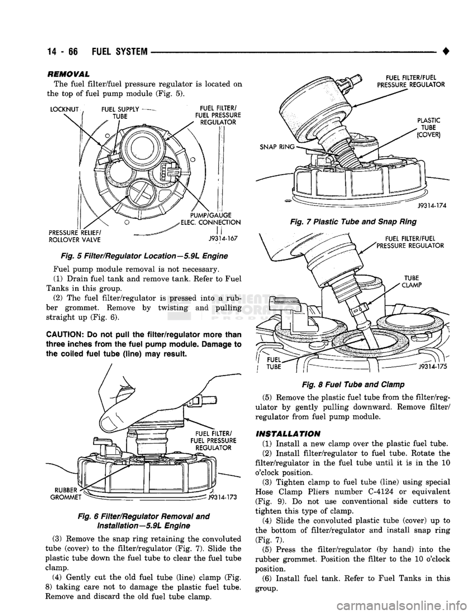
The fuel filter/fuel pressure regulator is located on
the top of fuel pump module (Fig. 5).
ROLLOVER
VALVE
J9314-167
Fig.
5 Filter/Regulator Location—5.9L
Engine
Fuel pump module removal is not necessary. (1) Drain fuel tank and remove tank. Refer to Fuel
Tanks in this group. (2) The fuel filter/regulator is pressed into a rub
ber grommet. Remove by twisting and pulling straight up (Fig. 6).
CAUTION;
Do not pull the
filter/regulator
more
than
three
inches
from
the
fuel
pump
module.
Damage
to
the
coiled
fuel
tube
(line)
may
result.
Fig.
6 Filter/Regulator
Removal
and Installation—5.9L
Engine
(3) Remove the snap ring retaining the convoluted
tube (cover) to the filter/regulator (Fig. 7). Slide the
plastic tube down the fuel tube to clear the fuel tube clamp.
(4) Gently cut the old fuel tube (line) clamp (Fig.
8) taking care not to damage the plastic fuel tube.
Remove and discard the old fuel tube clamp.
Fig.
7 Plastic Tube and
Snap
Ring
Fig.
8
Fuel
Tube and
Clamp
(5) Remove the plastic fuel tube from the filter/reg
ulator by gently pulling downward. Remove filter/
regulator from fuel pump module.
INSTALLATION
(1) Install a new clamp over the plastic fuel tube.
(2) Install filter/regulator to fuel tube. Rotate the
filter/regulator in the fuel tube until it is in the 10 o'clock position. (3) Tighten clamp to fuel tube (line) using special
Hose Clamp Pliers number C-4124 or equivalent (Fig. 9). Do not use conventional side cutters to
tighten this type of clamp.
(4) Slide the convoluted plastic tube (cover) up to
the bottom of filter/regulator and install snap ring (Fig. 7).
(5) Press the filter/regulator (by hand) into the
rubber grommet. Position the filter to the 10 o'clock
position.
(6) Install fuel tank. Refer to Fuel Tanks in this
group.
Page 962 of 1502
•
STEERING STEERING
19-1
CONTENTS
page
GENERAL INFORMATION
1
POWER STEERING PUMP
11
POWER STEERING SYSTEM DIAGNOSIS
..... 2
RECIRCULATING
BALL
POWER STEERING GEAR
. 20
page
STEERING COLUMN
3i
STEERING LINKAGE
17
TORQUE SPECIFICATIONS
40
GENERAL
INFORMATION
STEERING SYSTEM COMPONENTS
Dodge Trucks
use a
power
assisted recirculating-
ball
type steering gear
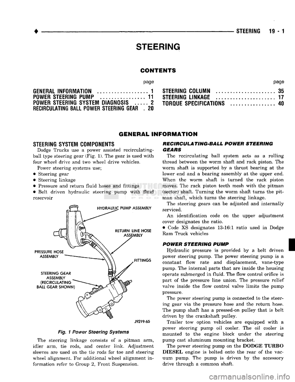
(Fig.
1). The
gear
is
used with
four
wheel drive
and two
wheel
drive
vehicles. Power steering systems
use;
•
Steering
gear • Steering linkage
• Pressure
and
return fluid hoses
and
fittings
• Belt driven hydraulic steering pump with
fluid
reservoir
J9219-65
Fig.
1
Power
Steering
Systems
The steering linkage consists
of a
pitman
arm,
idler
arm, tie
rods,
and
center link. Adjustment
sleeves
are
used
on the tie
rods
for toe and
steering
wheel alignment.
For
additional wheel alignment
in
formation refer
to
Group
2,
Front Suspension. RECIRCULA TING-BALL
POWER
STEERING
GEARS
The recirculating ball system acts
as a
rolling
thread between
the
worm shaft
and
rack piston.
The
worm shaft
is
supported
by a
thrust bearing
at the
lower
end
and a
bearing assembly
at
the
upper
end.
When
the
worm shaft
is
turned
the
rack piston
moves.
The
rack piston teeth mesh with
the
pitman (sector) shaft. Turning
the
worm shaft turns
the
pit
man shaft, which turns
the
steering linkage.
The steering gears
can be
adjusted
and
internally
serviced.
An identification code
on the
upper adjustment
cover designates
the
ratio.
• Code
XS
designates 13-16:1 ratio used
in
Dodge
Ram Truck vehicles
POWER
STEERING
PUMP
Hydraulic pressure
is
provided
by a
belt driven
power steering pump.
The
power steering pump
is a
constant flow rate
and
displacement, vane-type
pump.
The
internal parts that
are
inside
the
housing operate submerged
in
fluid.
The
flow control orifice
is
part
of
the
pressure line union.
The
pressure relief
valve inside
the
flow control valve limits
the
pump
pressure.
The power steering pump
is
connected
to
the
steer
ing gear
via the
pressure hose
and the
return hose.
The pump shaft
has
a
pressed-on pulley that
is
belt driven
by the
crankshaft pulley.
Trailer
tow
option vehicles
are
equipped with
a
power steering pump
oil
cooler.
The oil
cooler
is
mounted
to the
engine block under
the
steering
pump cast aluminum mounting bracket.
The power steering pump
on
the
DODGE TURBO
DIESEL engine
is
bolted onto
the
rear
of
the
vac
uum pump.
The
pump
is
driven
by the
accessory drive through
a
common shaft.
Page 1024 of 1502
NV4500
TRANSMISSION OVERHAUL
21 - 23
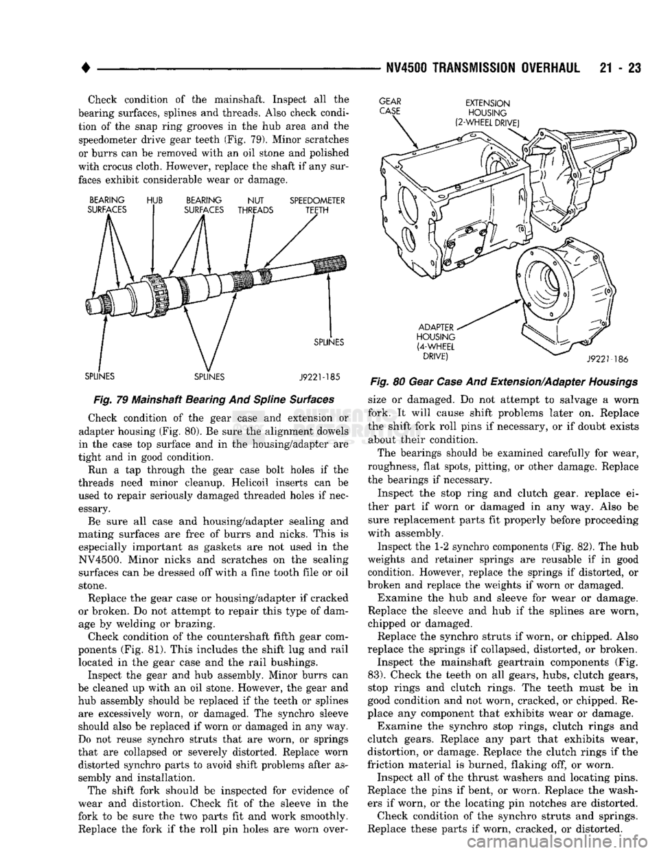
Check condition of the mainshaft. Inspect all the
bearing surfaces, splines and threads. Also check condi tion of the snap ring grooves in the hub area and the speedometer drive gear teeth (Fig. 79). Minor scratches
or burrs can be removed with an oil stone and polished
with crocus cloth. However, replace the shaft if any sur faces exhibit considerable wear or damage.
GEAR
CASE
BEARING
SURFACES HUB
BEARING
NUT
SURFACES THREADS SPEEDOMETER
TEETH
SPLINES SPLINES SPLINES
J922M85
Fig.
79 Mainshaft Bearing And
Spline
Surfaces
Check condition of the gear case and extension or
adapter housing (Fig. 80). Be sure the alignment dowels
in the case top surface and in the housing/adapter are
tight and in good condition.
Run a tap through the gear case bolt holes if the
threads need minor cleanup. Helicoil inserts can be used to repair seriously damaged threaded holes if nec
essary.
Be sure all case and housing/adapter sealing and
mating surfaces are free of burrs and nicks. This is especially important as gaskets are not used in the
NV4500. Minor nicks and scratches on the sealing surfaces can be dressed off with a fine tooth file or oil
stone.
Replace the gear case or housing/adapter if cracked
or broken. Do not attempt to repair this type of dam age by welding or brazing.
Check condition of the countershaft fifth gear com
ponents (Fig. 81). This includes the shift lug and rail located in the gear case and the rail bushings.
Inspect the gear and hub assembly. Minor burrs can
be cleaned up with an oil stone. However, the gear and hub assembly should be replaced if the teeth or splines are excessively worn, or damaged. The synchro sleeve
should also be replaced if worn or damaged in any way.
Do not reuse synchro struts that are worn, or springs
that are collapsed or severely distorted. Replace worn distorted synchro parts to avoid shift problems after as
sembly and installation.
The shift fork should be inspected for evidence of
wear and distortion. Check fit of the sleeve in the
fork to be sure the two parts fit and work smoothly.
Replace the fork if the roll pin holes are worn over-
EXTENSION
HOUSING
(2-WHEEL
DRIVE)
ADAPTER
HOUSING
(4-WHEEL
DRIVE)
J9221-186
Fig.
80 Gear
Case
And Extension/Adapter
Housings
size or damaged. Do not attempt to salvage a worn
fork. It will cause shift problems later on. Replace
the shift fork roll pins if necessary, or if doubt exists about their condition.
The bearings should be examined carefully for wear,
roughness, flat spots, pitting, or other damage. Replace
the bearings if necessary.
Inspect the stop ring and clutch gear, replace ei
ther part if worn or damaged in any way. Also be sure replacement parts fit properly before proceeding
with assembly.
Inspect the 1-2 synchro components (Fig. 82). The hub
weights and retainer springs are reusable if in good condition. However, replace the springs if distorted, or
broken and replace the weights if worn or damaged. Examine the hub and sleeve for wear or damage.
Replace the sleeve and hub if the splines are worn,
chipped or damaged. Replace the synchro struts if worn, or chipped. Also
replace the springs if collapsed, distorted, or broken. Inspect the mainshaft geartrain components (Fig.
83).
Check the teeth on all gears, hubs, clutch gears,
stop rings and clutch rings. The teeth must be in
good condition and not worn, cracked, or chipped. Re
place any component that exhibits wear or damage. Examine the synchro stop rings, clutch rings and
clutch gears. Replace any part that exhibits wear,
distortion, or damage. Replace the clutch rings if the
friction material is burned, flaking off, or worn. Inspect all of the thrust washers and locating pins.
Replace the pins if bent, or worn. Replace the wash ers if worn, or the locating pin notches are distorted. Check condition of the synchro struts and springs.
Replace these parts if worn, cracked, or distorted.
Page 1077 of 1502
21 - 76
AUTOMATIC
TRANSMISSION—32RH/36RH/37RH/42RH/46RH
•
TORQUE
CONVERTER
A three element torque converter is used. The con
verter used with 32RH and some 36RH transmis sions has a modulated converter clutch. The
converter used with 37RH transmissions is not
equipped with a modulated clutch. The converter used with 1993, 32RH transmissions
is new. The converter hub was changed to accept the
new style drive flats on the oil pump inner gear. The
new style converter is not interchangeable with pre
vious designs. A 241 or 273 mm (9.5 or 10.75 in.) converter is
used for 3.9L, 5.2L and 5.9L gas engine applications.
A 310 mm (12.2 in.) converter is used for diesel en
gine applications. The converter impeller is connected to the engine
crankshaft through the front cover which is welded
to the impeller. The turbine is splined to the trans
mission input shaft and the stator is splined to the transmission reaction shaft. The converter is a welded assembly. It is not a re
pairable component and is serviced as an assembly.
RECOMMENDED
FLUID
The recommended and preferred fluid for Chrysler
automatic transmissions is Mopar ATF Plus, Type
7176.
Use Mopar Dexron II only when ATF Plus is
not readily available.
TRANSMISSION
IDENTIFICATION
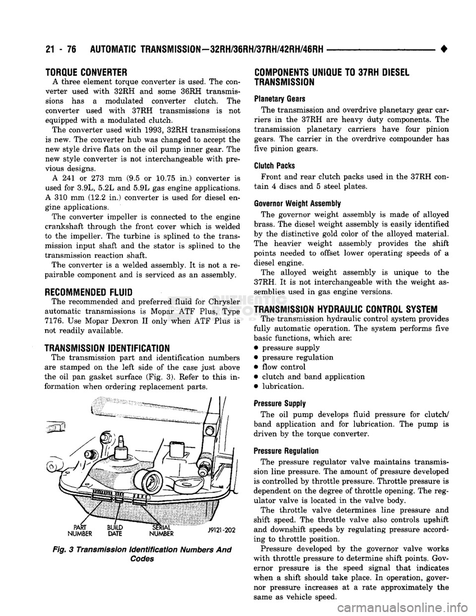
The transmission part and identification numbers
are stamped on the left side of the case just above
the oil pan gasket surface (Fig. 3). Refer to this in formation when ordering replacement parts.
PART
NUMBER BUILD
DATE SERIAL
19191-909
NUMBER JVUI zuz
Fig.
3
Transmission
Identification
Numbers
And
Codes
COMPONENTS
UNIQUE
TO
37RH
DIESEL
TRANSMISSION
Planetary
Gears
The transmission and overdrive planetary gear car
riers in the 37RH are heavy duty components. The
transmission planetary carriers have four pinion
gears.
The carrier in the overdrive compounder has
five pinion gears.
Clutch
Packs
Front and rear clutch packs used in the 37RH con
tain 4 discs and 5 steel plates.
Governor
Weight
Assembly
The governor weight assembly is made of alloyed
brass.
The diesel weight assembly is easily identified
by the distinctive gold color of the alloyed material.
The heavier weight assembly provides the shift
points needed to offset lower operating speeds of a diesel engine.
The alloyed weight assembly is unique to the
37RH. It is not interchangeable with the weight as semblies used in gas engine versions.
TRANSMISSION
HYDRAULIC
CONTROL
SYSTEM
The transmission hydraulic control system provides
fully automatic operation. The system performs five
basic functions, which are: • pressure supply
• pressure regulation • flow control
• clutch and band application
• lubrication.
Pressure
Supply
The oil pump develops fluid pressure for clutch/
band application and for lubrication. The pump is driven by the torque converter.
Pressure
Regulation
The pressure regulator valve maintains transmis
sion line pressure. The amount of pressure developed
is controlled by throttle pressure. Throttle pressure is
dependent on the degree of throttle opening. The reg
ulator valve is located in the valve body.
The throttle valve determines line pressure and
shift speed. The throttle valve also controls upshift
and downshift speeds by regulating pressure accord
ing to throttle position.
Pressure developed by the governor valve works
with throttle pressure to determine shift points. Gov ernor pressure is the speed signal that indicates
when a shift should take place. In operation, gover
nor pressure increases at a rate approximately the same as vehicle speed.
Page 1082 of 1502
•
AUTOMATIC
TRANSMISSION—32RH/36RH/37RH/42RH/46RH
21 - 81
TORQUE
CONVERTER
A three element torque converter
is
used
for all ap
plications.
The
converter consists
of the
impeller,
sta-
tor
and
turbine.
The
converter also contains
an
overrunning clutch
and a
modulated converter clutch
mechanism.
The converter used with
1993,
42RH transmissions
is
new. The
converter
hub was
changed
to
accept
the
new style drive flats
on the oil
pump inner gear.
The
new style converter
is not
interchangeable with pre
vious designs.
The converter modulated clutch consists
of a
slid
ing clutch piston, clutch springs
and the
clutch disc
friction material.
The
clutch provides optimum
torque transfer
and
economy when engaged.
The clutch disc
is
attached
to the
converter front
cover.
The
clutch piston
and
clutch springs
are at
tached
to the
turbine
hub. The
springs dampen
en
gine firing impulses
and
loads during
the
initial
phase
of
converter clutch engagement.
Clutch engagement
is
controlled
by the
converter
clutch valve
and
solenoid. Both
are
located
on the
transmission valve body. Clutch engagement occurs in drive range
at
speeds above approximately 30-35
mph.
The clutch provides reduced engine speed
and
greater fuel economy when engaged. Clutch engage
ment also provides reduced transmission fluid tem
peratures.
COMPONENTS
UNIQUE
TO
DIESEL VERSION
OF
46RH
Planetary
Gears
The transmission
and
overdrive planetary gear car
riers
in the
diesel version
of the
46RH
are
heavy duty components.
The
transmission planetary carriers have four pinion gears.
The
carrier
in the
over
drive compounder
has
five pinion gears.
The
heavy
duty planetary units
are
unique
to the
diesel 46RH.
Clutch
Packs
Clutch packs used
in the
diesel version
of the
46RH contain
the
following number
of
discs
and
plates:
• transmission front/rear clutch
has 4
discs
and 5
steel plates
• overdrive clutch
has 5
discs
and 6
steel plates
• overdrive direct clutch
has 8
discs
and 9
steel
plates
Governor
Weight
Assembly
The governor weight assembly
in the
diesel 46RH
is made
of
alloyed brass.
The
diesel weight assembly
is easily identified
by the
distinctive gold color
of the
alloyed material.
The
heavier weight assembly pro
vides
the
shift points needed
to
offset lower operating speeds
of a
diesel engine. The alloyed weight assembly
is
unique
to the
diesel
46RH.
It is not
interchangeable with
the
weight
as
semblies used
in gas
engine versions.
Diesel
Thermo
Switch
Fourth gear operation
in the
diesel 46RH
is
also
controlled
by two
temperature sensitive thermo- switches.
The first thermo-switch
is the
engine coolant tem
perature switch. This switch prevents overdrive fourth gear operation when engine coolant tempera
ture
is
below approximately
65° F.
The second thermo-switch directly monitors trans
mission fluid temperature.
The
switch will either
downshift
the
transmission
to
third gear,
or
prevent a
3-4
upshift when fluid temperature exceeds
270-275°
F.
The fluid temperature switch
is
located
in a
boss
built into
the
cooler outlet line.
The
boss
and
switch are located approximately
2-3
inches from
the
outlet
line fitting
in the
transmission case.
The engine coolant
and
fluid temperature switches
are
in
circuit with
the
overdrive control switch
in the
instrument panel.
GEAR RATIOS
42RH forward gear ratios
are:
First gear
=
2.74:1
Second gear
= 1.54:1
Third gear
= 1.00:1
Fourth gear
=
0.69:1.
46RH forward gear ratios
are:
First gear
=
2.45:1 Second gear
= 1.45:1
Third gear
= 1.00:1
Fourth gear
=
0.69:1.
RECOMMENDED
FLUID
The recommended
and
preferred fluid
for
42RH/
46RH transmissions
is
Mopar
ATF
Plus, type
7176.
Use Mopar Dexron
II
only when
ATF
Plus
is not
readily available.
TRANSMISSION
IDENTIFICATION
The transmission part
and
identification numbers
and codes
are
stamped
on the
left side
of the
case
just above
the oil pan
gasket surface
(Fig. 3).
The first letter/number group
is the
assembly part
number.
The
next number group
the
transmission
build date.
The
last number group
is the
transmis sion serial number. Refer
to
this information when
ordering replacement parts.
FOURTH
GEAR OVERDRIVE COMPONENTS
42RH/46RH models have three transmission shafts.
An intermediate shaft
is
positioned between
the in
put
and
output shafts.
The
output shaft
is in the
Page 1104 of 1502
•
AUTOMATIC
TRANSMISSION—32RH/36RH/37RH/42RH/46RH
21-103
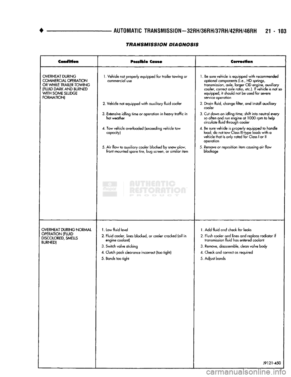
TRANSMISSION DIAGNOSIS
Condition
Possible
Couso
Correction
OVERHEAT
DURING
COMMERCIAL
OPERATION
OR
WHILE
TRAILER
TOWING
(FLUID
DARK
AND
BURNED
WITH
SOME
SLUDGE
FORMATION)
1.
Vehicle not properly equipped for
trailer
towing or
commercial use
2. Vehicle not equipped
with
auxiliary fluid cooler
3.
Extensive idling
time
or operation in heavy
traffic
in hot weather
4. Tow vehicle overloaded (exceeding vehicle tow capacity)
5. Air flow to auxiliary cooler blocked by snow plow,
front
mounted spare
tire,
bug screen, or similar
item
1.
Be sure vehicle is equipped
with
recommended
optional components
(i.e.,
HD
springs,
transmission,
axle, larger CID engine, auxiliary cooler, correct axle ratio, etc.). If vehicle is not so
equipped, it should not be used for severe
service operation
2. Drain fluid, change
filter,
and install auxiliary cooler
3.
Cut down on idling time; shift into
neutral
every
so
often and run engine at 1000 rpm to help
circulate fluid through cooler
4. Be sure vehicle is properly equipped to handle
load;
do not tow
Class
Ill-type loads
with
a
vehicle
that
is only
rated
for
Class
1
or II operation
5.
Remove or reposition
item
causing
air flow
blockage
OVERHEAT
DURING
NORMAL
OPERATION
(FLUID
DISCOLORED,
SMELLS
BURNED)
1.
Low
fluid
level
2. Fluid cooler, lines blocked, or cooler cracked (oil in engine coolant)
3.
Switch valve sticking
4. Clutch pack clearance incorrect (too tight)
5.
Bands
too tight 1. Add
fluid
and check for leaks
2. Flush cooler and lines and replace radiator if
transmission
fluid has
entered
coolant
3.
Remove,
disassemble,
clean valve body
4. Check and correct as required
5. Adjust bands
J9121-450
Page 1131 of 1502
21
-
130
IN-VEHICLE
SERVICE-~32RH/36RH/37RH/42RH/4iRH
•
IN-VEHICLE
SERVICE-32RH/36RH/37RH/42RH/46RH
INDEX
page
Aluminum Thread Repair
141
Checking
Fluid
Level
130
Extension Housing Bushing
and
Output
Shaft
Bearing
Service-32RH/36RH/37RH
... .
135
Extension Housing Yoke Seal Replacement
....
135
Fluid
and Filter
Change
130
Front
Band
Adjustment
133
Gearshift Linkage
Adjustment
130
Governor
and
Park Gear Service—
32RH/36RH/37RH
137
Governor
and
Park Lock Service—42RH/46RH
.
138
CHECKING
FLUID LEVEL
(1) Position vehicle
on
level surface. This
is ex
tremely important
for
accurate check.
(2)
Apply parking brakes
and run
engine
at
curb
idle speed.
(3)
Shift transmission momentarily into
all
gear
ranges. Then shift back
to
Neutral.
(4)
Clean
top of
filler tube
and
dipstick
(to
avoid
dirt entry)
and
check fluid level. Correct level
is as
follows:
(5)
Be
sure fluid
is at
normal operating tempera
ture (180°F). Correct level
is
between "Maximum Level
Hot"
and
"Add"
marks (crosshatched area)
on
dipstick. (6)
If
fluid level
is
low,
add
only enough fluid
to
correct level.
CAUTION:
Do not
overfill
the
transmission. Overfilling
will
force fluid
out
the
pump vent which
can
be
mistaken
for
a
pump seal leak. Overfilling
will
also
cause
fluid aeration
and foaming
when
the
excess
fluid
is
picked
up
and
churned
by
the
gear train. Aeration
will
reduce fluid
life
significantly.
FLUID
AND
FILTER
CHANGE
Normal Change
Interval
The fluid
and
filter should
be
changed
(and the
bands adjusted)
at
recommended maintenance inter
vals.
Or
whenever
the
transmission
has
been disassembled
for
any
reason.
Recommended Fluid
The recommended
(and
preferred) fluid
for
Chrysler automatic transmissions
is
Mopar
ATF
Plus,
type
7176.
Use
Mopar Dexron
II
only when
ATF Plus
is not
readily available.
page
Park Lock
Service-32RH/36RH/37RH
. 138
Park/Neutral Position Switch
134
Rear
Band
Adjustment
133
Speedometer Service
134
Transmission Cooler Service
140
Transmission
Throttle
Cable
Adjustment-
Cummins Diesel Engine
132
Transmission
Throttle
Cable
Adjustment-
Gas
Engines
131
Valve Body
Control
Pressure Adjustments
.....
140
Valve Body Service
138
Severe Usage Change
Interval
Under severe usage,
the
fluid
and
filter should
be
changed
and the
bands adjusted
at
12,000 mile (19,000
km)
intervals.
Severe usage
is
defined
as:
• More than half
of
vehicle operation occurs
in
heavy city traffic during
hot
weather
at
ambient
temperatures above
90°
F.
• Vehicle
is
used
for
Taxi, Police, Limousine,
or
sim
ilar commercial operations.
• Vehicle
is
used
for
trailer/boat towing
or
heavy
load hauling. When
the
factory fluid
is
drained, refill
the
trans
mission with Mopar
ATF
Plus, type
7176
fluid.
Mo
par Dexron
II
can
be
used
if
ATF
Plus
is
not
readily available.
FLUID
AND
FILTER
REPLACEMENT
PROCEDURE
(1) Raise vehicle, remove
oil pan
and
drain fluid.
(2) Remove filter screws
and
remove filter.
(3) Position
new
filter
on
valve body
and
install fil
ter screws finger tight. (4) Tighten filter screws
to 4
N*m (35
in.
lbs.)
with
torque wrench.
(5) Position
new
gasket
on oil pan
and
install
pan
on transmission. Tighten
pan
bolts
to 17
N»m
(150
in.
lbs.)
torque. (6) Lower vehicle
and
refill transmission with rec
ommended fluid.
GEARSHIFT LINKAGE ADJUSTMENT
Check linkage adjustment
by
starting
the
engine
in Park
and
Neutral. Adjustment
is
OK
if
the
engine starts only
in
park
and Neutral. Adjustment
is
incorrect
if
the
engine starts
in one
but
not
both positions. If
the
engine starts
in
any
position other than Park
or Neutral,
or if
the
engine will
not
start
at
all,
the
park/neutral position switch
may
be
faulty.
Page 1135 of 1502
21
- 134
IN-WEHiCLE SER¥iCE-32RH/3IRH/37RH/42RH/46RH
• • On 36RH/37RH746RH, back off adjusting screw
two turns. (6) Hold adjusting screw in place with backup
wrench. Then tighten locknut to 34 N*m (25 ft. lbs.) torque.
(7) Position new gasket on oil pan and install pan
on transmission. Tighten pan bolts to 17 N»m (13 ft.
lbs.) torque.
(8) Lower vehicle and refill transmission with Mo
par ATF Plus, type 7176, or Dexron II™ fluid.
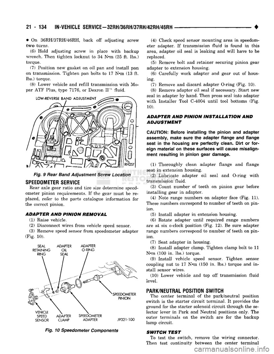
Fig. § Rear Band Adjustment Screw Location
SPEEDOMETER
SERVICE
Rear axle gear ratio and tire size determine speed
ometer pinion requirements. If the gear must be re
placed, refer to the parts catalogue information for
the correct pinion.
ADAPTER
AND
PINION REMOWAL
(1) Raise vehicle.
(2) Disconnect wires from vehicle speed sensor.
(3) Remove speed sensor from speedometer adapter
(Fig. 10). SEAL ADAPTER ADAPTER
RETAINING OIL O-RING
SPEED ADAPTER SPEEDOMETER
SENSOR CLAMP ADAPTER J932M00
Fig. 10 Speedometer Components (4) Check speed sensor mounting area in speedom
eter adapter. If transmission fluid is found in this area, adapter oil seal is leaking and will have to be
replaced. (5) Remove bolt and retainer securing pinion gear
adapter to extension housing. (6) Carefully work adapter and gear out of hous
ing. (7) Remove and discard adapter O-ring (Fig. 10).
(8) Remove adapter oil seal if necessary. Start new
seal in adapter by hand. Then press seal into adapter
with Installer Tool C-4004 until tool bottoms (Fig.
10).
ADAPTER AND PINION INSTALLATION AND
ADJUSTMENT
CAUTION:
Before installing
the
pinion
and
adapter
assembly,
make sure
the
adapter flange
and
flange
seat
in the
housing
are
perfectly clean. Dirt
or
for
eign
material
on
these surfaces
will
cause misalign ment resulting
in
pinion gear damage.
(1) Thoroughly clean adapter flange and flange
seat in extension housing.
(2) Lubricate adapter oil seal and O-ring with
transmission fluid.
(3) Count number of teeth on pinion gear before
installing gear in adapter.
(4) Note range numbers on adapter face (Fig. 11).
These numbers correspond to number of teeth on pin ion.
(5) Install adapter in extension housing.
(6) Rotate adapter until required range numbers
are at six o-clock position (Fig. 12). Be sure adapter
range numbers correspond to number of teeth on pin ion.
(7) Seat adapter in housing.
(8) Install adapter clamp. Tighten clamp bolt to 11
N*m (100 in. lbs.) torque.
(9) Install vehicle speed sensor. Tighten sensor
coupling nut to 17 N*m (150 in. lbs.) torque and in
stall sensor wires.
(10) Lower vehicle and top off transmission fluid
level.
PARK/NEUTRAL
POSITION SWJTCH
The center terminal of the park/neutral position
switch is the starter circuit terminal. It provides the
ground for the starter solenoid circuit through the se
lector lever in Park and Neutral positions only. The
outer terminals on the switch are for the backup
lamp circuit.
SWITCH TEST To test the switch, remove the wiring connector.
Then test continuity between the center terminal