1993 DODGE TRUCK oil type
[x] Cancel search: oil typePage 160 of 1502
•
REAR
SUSPENSION
AND
AXLE
3 - 33
WHEEL BEARING SERVICE
REMOVAL (1) Remove the axle shaft, refer to the removal
procedure. (2) Remove the nut lock and adjustment nut.
(3) Remove the hub and drum assembly. The outer
wheel bearing will slide out as the hub is being re
moved. (4) Place hub on bench and remove inner grease
seal. Discard seal. (5) Remove inner wheel bearing. Inspect wheel
bearings for wear. Replace as necessary.
CLEANING AND INSPECTION (1) Thoroughly clean both wheel bearings and in
terior of the hub. Remove all of the residual lubri cant. (2) To clean the bearings:
• Soak them in an appropriate cleaning solvent
• Strike the flat of each bearing against a hardwood
block several times • Flush bearing between strikes
• Repeat the procedure above until each bearing is clean
• Dry the bearings with compressed air but do not
spin them (3) After cleaning, apply engine oil to each bear
ing. (4) Rotate each bearing slowly while applying
downward force. Examine the rollers for pitting and
roughness. Replace worn or otherwise defective bear
ings.
If a bearing has pitted and/or rough surfaced
rollers, replace both the bearing and bearing cup. (5) If reusable, remove the engine oil from each
bearing. Pack each bearing with multi-purpose
NLGI, grade 2, EP-type lubricant. Ensure that lubricant is forced into all the cav
ities between the bearing cage and rollers.
INSTALLATION (1) If a bearing and cup must be replaced, remove
the cup from the hub bore. Use a brass drift or an appropriate removal tool to tap out the cup. (2) Install the replacement bearing cup(s) with an
appropriate installation tool.
(3) Apply lubricant to surface area of the hub bore.
Install the inner wheel bearing in the hub. Install a
replacement bearing seal with an appropriate seal installation tool. (4) Inspect the bearing and seal contact surfaces on
the axle for burrs and/or roughness.
(5) Remove all the rough contact surfaces from the
axle.
Apply a coating of multi-purpose NLGI, grade
2,
EP-type lubricant to the axle.
CAUTION:
Use care to prevent the inner
wheel
bear
ing
and bearing
seal
from contacting the axle
threads
during installation. Otherwise, the
threads,
bearing,
and
seal
could
be
damaged.
(6) Carefully slide the hub onto the axle. Install
the outer wheel bearing, the locktab and outer wheel
bearing locknut.
(7) Tighten the adjustment nut to 163-190 Nnn
(120-140 ft. lbs.) torque while rotating the wheel. (8) Loosen the adjustment nut 1/3 of-a-turn (120
degrees) to provide 0.001-inch to 0.008-inch wheel
bearing end play.
(9) Tap the nut lock into the spindle keyway and
adjustment nut.
(10) Install the axle shaft, refer to the installation
procedure.
COMPLETE AXLE REMOVAL/INSTALLATION
REMOVAL It is not necessary to remove the complete axle
from the vehicle for routine or differential service. If
the differential housing or axle shaft tubes are dam aged, the complete axle can be removed and in
stalled.
(1) Raise the rear of the vehicle until the rear
wheels are not contacting the surface. Support the
vehicle body at the front of the rear springs.
(2) Use a wooden block to retain the brake pedal
in the up position.
(3) Remove the axle shafts, wheels, hubs and
brake drums. If necessary, refer to the applicable re moval procedures.
(4) Disconnect the brake line and cap the fittings
to prevent loss of brake fluid. (5) Disconnect the parking brake cables.
Scribe installation alignment reference marks
on drive shaft U-joint and on pinion yoke. (6) Disconnect the drive shaft U-joint from the pin
ion yoke. Secure it in an upright position to prevent
damage to the U-joint.
(7) Remove the rear shock absorbers and the rear
spring U-bolts from the axle. (8) Remove the rear axle from the vehicle.
INSTALLATION (1) If the differential housing cover was removed,
ensure differential housing and cover mating sur
faces are clean.
(2) If cover was removed, apply a bead of MOPAR
Silicone Rubber Sealant around the cover bolt circle.
Install the differential housing cover. Tighten the
cover bolts to 47 N»m (35 ft. lbs.) torque. Install the axle gear ratio identification tag under one of
the cover bolts.
(3) With the vehicle body supported at the front of
the rear springs, position the axle under the rear springs.
Page 209 of 1502
5
- 22
BRAKES
POWER BRAKE
VACUUM
PUMP—DIESEL ENGINE
INDEX
page
General
Information
22
Low
Vacuum
Warning
Switch
22
Pump
Adapter
Replacement
. 25
Vacuum
Pump
Diagnosis
..................
23
Vacuum
Pump
Operation
..................
23
page
Vacuum
Pump
Replacement
24
Vacuum
Pump
Serviceability
22
Vacuum—Steering
Pump
Assembly
Installation
. . 26
Vacuum—Steering
Pump
Assembly
Removal
... 23
GENERAL
INFORMATION
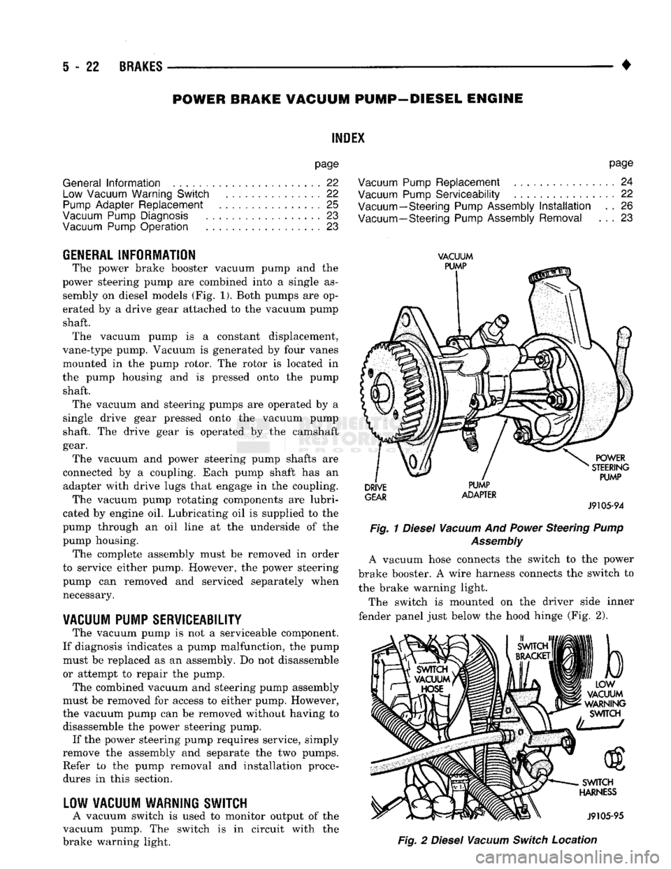
The power brake booster vacuum pump
and the
power steering pump
are
combined into
a
single
as
sembly
on
diesel models
(Fig. 1).
Both pumps
are op
erated
by a
drive gear attached
to the
vacuum pump shaft. The vacuum pump
is a
constant displacement,
vane-type pump. Vacuum
is
generated
by
four vanes
mounted
in the
pump rotor.
The
rotor
is
located
in
the pump housing
and is
pressed onto
the
pump shaft. The vacuum
and
steering pumps
are
operated
by a
single drive gear pressed onto
the
vacuum pump
shaft.
The
drive gear
is
operated
by the
camshaft
gear. The vacuum
and
power steering pump shafts
are
connected
by a
coupling. Each pump shaft
has an
adapter with drive lugs that engage
in the
coupling. The vacuum pump rotating components
are
lubri
cated
by
engine
oil.
Lubricating
oil is
supplied
to the
pump through
an oil
line
at the
underside
of the
pump housing. The complete assembly must
be
removed
in
order
to service either pump. However,
the
power steering
pump
can
removed
and
serviced separately when necessary.
VACUUM
PUMP
SERVICEABILITY
The vacuum pump
is not a
serviceable component.
If diagnosis indicates
a
pump malfunction,
the
pump must
be
replaced
as an
assembly.
Do not
disassemble
or attempt
to
repair
the
pump.
The combined vacuum
and
steering pump assembly
must
be
removed
for
access
to
either pump. However,
the vacuum pump
can be
removed without having
to
disassemble
the
power steering pump. If
the
power steering pump requires service, simply
remove
the
assembly
and
separate
the two
pumps. Refer
to the
pump removal
and
installation procedures
in
this section.
LOW
VACUUM
WARNING
SWITCH
A vacuum switch
is
used
to
monitor output
of the
vacuum pump.
The
switch
is in
circuit with
the
brake warning light.
VACUUM
PUMP
DRIVE
GEAR
PUMP
ADAPTER
POWER
STEERING
PUMP
J9105-94
Fig.
1
Diesel
Vacuum
And
Power
Steering
Pump
Assembly
A vacuum hose connects
the
switch
to the
power
brake booster.
A
wire harness connects
the
switch
to
the brake warning light.
The switch
is
mounted
on the
driver side inner
fender panel just below
the
hood hinge
(Fig. 2),
b
LOW
VACUUM
WARNING
SWITCH
SWITCH
HARNESS
J9105-95
Fig.
2
Diesel
Vacuum
Switch
Location
Page 255 of 1502
6
- 2
CLUTCH
•
CLUTCH DIAGNOSIS
INDEX
page
Clutch Problem
Causes
, 2
General
Diagnosis
Information
2
GENERAL
DIAGNOSIS INFORMATION
Unless the cause of a clutch problem is obvious, a
road test and component inspection will be required
for accurate diagnosis. A road test will help determine the type of fault
while component inspection will identify the problem component. During a road test, drive the vehicle at normal
speeds. Shift the transmission through all gear
ranges and observe clutch action. If chatter, grab, slip, or improper release is experi
enced, remove and inspect the clutch components.
However, if the problem is noise or hard shifting,
further diagnosis is needed. The transmission or an
other driveline component may actually be at fault. Careful observation during a road test will help
narrow the problem area.
CLUTCH PROBLEM
CAUSES
CONTAMINATION Fluid contamination is one of the more common
causes of clutch malfunctions. Oil, water, or clutch
fluid on the clutch contact surfaces will result in
faulty operation. The usual result is chatter, slip, or
grab.
During inspection, note if any components are con
taminated with oil, hydraulic fluid, or water/road splash.
Oil contamination indicates a leak at either the
rear main seal or transmission input shaft.
Oil leakage produces a residue of oil on the hous
ing interior and on the clutch cover and flywheel.
Heat buildup caused by slippage between the cover,
disc and flywheel, can sometimes bake the oil residue
onto the components. The glaze-like residue ranges
in color from amber to black.
Road splash contamination means dirt and water
are entering the clutch housing due to loose bolts,
housing cracks, vent openings, or through the slave
cylinder opening. Driving through deep water pud
dles can force water/road splash into the housing
through such openings.
An additional problem caused by water contamina
tion and especially by steam cleaning, involves
clutch disc sticking and poor release. Water and steam vapors can be absorbed by the
clutch facing material. If the vehicle sits idle for long
page
Inspection
and
Diagnosis
Charts 5
periods after water contamination, the force exerted
by the pressure plate may cause the disc to bond it self to the flywheel or pressure plate.
Frequently, the only remedy for the above condi
tion is component replacement. To avoid this prob
lem, a vehicle should be driven as soon as possible to
heat and dry the clutch components.
Clutch fluid leaks are from a loose or damaged
slave cylinder line or connection. However, clutch
fluid leaks will usually be noted and corrected before severe contamination occurs.
CLUTCH MISALIGNMENT
Clutch components must be in proper alignment
with the crankshaft and transmission input shaft.
Misalignment caused by excessive runout or warpage of any clutch component will cause grab, chatter and improper clutch release.
Flywheel
Runout
Common causes of runout are heat warping, im
proper machining, mounting the flywheel on a dirty crankshaft flange, incorrect bolt tightening, or im
proper seating on the crankshaft flange shoulder.
Very light scratches or surface roughness on the
flywheel face can be cleaned up by scuff sanding with 180 grit emery cloth. However, if the surface is
warped or severely scored, replace the flywheel.
Do not machine the flywheel. The flywheel
face is manufactured with a unique surface con
tour. Machining would negate this feature and could result in unsatisfactory operation.
Clean the crankshaft flange before mounting the
flywheel. Dirt and grease on the flange surface may cock the flywheel causing runout.
Use new bolts when remounting a flywheel and se
cure the bolts with Mopar Lock And Seal, or Loctite
242.
Tighten flywheel bolts to specified torque only.
Overtightening could distort the flywheel hub caus
ing runout.
Clutch
Cover
And Disc
Runout
Check the clutch disc before installation. Axial
(face) runout of a new disc should not exceed 0.5 mm
(0.020 in.). Measure runout about 6 mm (1/4 in.)
from the outer edge of the disc facing. Obtain an other disc if runout is excessive.
Page 262 of 1502
•
CLUTCH
6 - 9 CLUTCH GRAB/CHATTER
Condition
Found
Cause
T
Correction
1.
Clutch
disc
facing covered
with
oil, grease, or clutch fluid. a) Oil leak at
rear
main or input
shaft seal.
b) Too much grease applied to
splines
or
disc
and input shaft. a) Correct leak and replace
disc
(do not clean and reuse the
disc).
b) Apply lighter grease coating to splines and replace
disc
(do not clean and reuse the disc).
2. Clutch
disc
and/or cover warped, or
disc
facings
exhibit
unusual
wear or appear to be
wrong type. Incorrect or substandard parts.
Replace
disc
and/or cover
with
correct parts.
3. Clutch master or slave cylinder plunger dragging-binding. a) Master or slave cylinder
components worn or corroded. a) Replace both cylinders as
assembly
(and reservoir).
4. No
fault
found
with
clutch
components.
a) Problem actually
related
to
suspension
or driveline
component.
b) Engine
related
problem. a)
Further
diagnosis
required.
Check
engine/transmission
mounts,
propeller shafts and U-joints, tires,
suspension
attaching parts and other
driveline components as needed.
b) Check EFI and igniton
systems.
5.
Partial
engagement of clutch
disc
(one side worn-opposite
side
glazed and lightly worn). a) Clutch pressure
plate
position
setting incorrect or modified.
b) Clutch cover, spring, or release fingers bent, distorted (rough
handling,
improper assembly).
c) Clutch
disc
damaged or distorted.
d) Clutch misalignment. a) Replace clutch cover and
disc.
b) Replace clutch cover and
disc.
c) Replace
disc.
d) Check alignment and runout of flywheel,
disc,
or cover and/or clutch
housing.
Correct as
necessary.
J9006-23
Page 293 of 1502
7 - 22
COOLING
SYSTEM
•
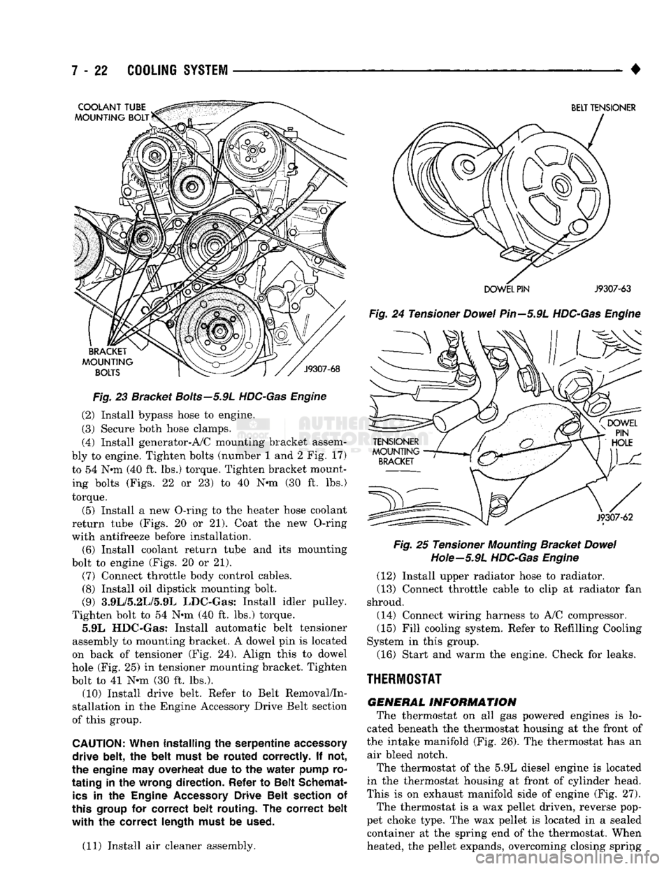
Fig.
23 Bracket
Bolts—5.9L
HDC-Gas Engine
(2) Install bypass hose to engine.
(3) Secure both hose clamps.
(4) Install generator-A/C mounting bracket assem
bly to engine. Tighten bolts (number 1 and 2 Fig. 17)
to 54 Nnn (40 ft. lbs.) torque. Tighten bracket mount ing bolts (Figs. 22 or 23) to 40 N-m (30 ft. lbs.)
torque.
(5) Install a new O-ring to the heater hose coolant
return tube (Figs. 20 or 21). Coat the new O-ring
with antifreeze before installation. (6) Install coolant return tube and its mounting
bolt to engine (Figs. 20 or 21). (7) Connect throttle body control cables.
(8) Install oil dipstick mounting bolt.
(9) 3.9L/5.2L/5.9L LDC-Gas: Install idler pulley.
Tighten bolt to 54 Nnn (40 ft. lbs.) torque. 5.9L HDC-Gas: Install automatic belt tensioner
assembly to mounting bracket. A dowel pin is located
on back of tensioner (Fig. 24). Align this to dowel
hole (Fig. 25) in tensioner mounting bracket. Tighten
bolt to 41 N-m (30 ft. lbs.). (10) Install drive belt. Refer to Belt Removal/In
stallation in the Engine Accessory Drive Belt section
of this group.
CAUTION:
When installing
the
serpentine
accessory
drive belt,
the
belt must
be
routed correctly.
If not,
the engine
may
overheat
due to the
water pump
ro
tating
in the
wrong direction. Refer
to
Belt Schemat
ics
in the
Engine
Accessory
Drive Belt section
of
this
group
for
correct belt routing.
The
correct belt
with the
correct length must
be
used.
(11) Install air cleaner assembly.
BELT TENSIONER
DOWEL PIN
J9307-63
Fig.
24 Tensioner
Dowel
Pin—5.9L
HDC-Gas Engine Fig.
25 Tensioner
Mounting
Bracket
Dowel
Hote—5.9L
HDC-Gas Engine
(12) Install upper radiator hose to radiator.
(13) Connect throttle cable to clip at radiator fan
shroud.
(14) Connect wiring harness to A/C compressor. (15) Fill cooling system. Refer to Refilling Cooling
System in this group.
(16) Start and warm the engine. Check for leaks.
THERMOSTAT
GENERAL
INFORMATION
The thermostat on all gas powered engines is lo
cated beneath the thermostat housing at the front of
the intake manifold (Fig. 26). The thermostat has an air bleed notch.
The thermostat of the 5.9L diesel engine is located
in the thermostat housing at front of cylinder head.
This is on exhaust manifold side of engine (Fig. 27). The thermostat is a wax pellet driven, reverse pop
pet choke type. The wax pellet is located in a sealed container at the spring end of the thermostat. When
heated, the pellet expands, overcoming closing spring
Page 350 of 1502
•
BATTERY/STARTER/GENERATOR
SERVICE
8B - 9
Load
Test
(Amps)
cold
Cranking
Rating
@ 0°F
Reserve
Capacity
300 Amp 600 Amp 120 Minutes
405 Amp 810 Amp 133 Minutes
535 Amp 1075 Amp
170 Minutes
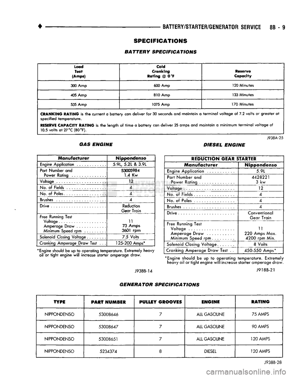
CRANKING
RATING
is the
current
a
battery
can
deliver
for 30
seconds
anej
maintain
a
terminal
voltage
of 7.2
volts
or
greater
at
specified
temperature.
RESERVE
CAPACITY RATING
is the
length
of
time
a
battery
can
deliver
25
amps and maintain
a
minimum
terminal
voltage
of
10.5 volts
at
27 °C (80
°F).
J938A-25
GAS ENGINE DIESEL ENGINE
Manufacturer
Nippondenso
Engine
Application 5.9L, 5.2L
&
3.9L
Part Number and
53005984
Power Rating
1.4
Kw
Voltage
12
No.
of
Fields 4
No.
of
Poles. 4
Brushes
4
Drive Reduction
Gear
Train
Free
Running Test Voltage 11
Amperage Draw 73 Amps
Minimum Speed
rpm
3601
rpm
Solenoid
Closing Voltage 7.5 Volts
Cranking Amperage Draw Test
. . .
125-200
Amps*
*
Engine
should be up to operating
temperature.
Extremely heavy oil
or
tight engine
will
increase
starter
amperage draw.
J938B-14
REDUCTION
GEAR
STARTER
Manufacturer
Nippondenso
Engine
Application 5.9L
Part Number
and
Power Rating
4428221
3
kw
Voltage
12
No.
of
Fields
4
No.
of
Poles 4
Brushes
4
Drive Conventional
Gear Train
Free
Running Test Voltage
Amperage Draw
Minimum Speed
rpm
11
220 Amps Max.
4200
rpm Min.
Solenoid
Closing Voltage 8 Volts
Cranking Amperage Draw Test
. .
450-550
Amps*
*
Engine
should
be up to
operating
temperature.
Extremely heavy oil or tight engine
will
increase
starter
amperage draw.
J918B-21
GENERATOR SPECIFICATIONS
TYPE
PHUT
HUMSIR
PULLEY
GROOVES
ENGINE
RATING
NIPPONDENSO
53008646
7
ALL GASOLINE 75 AMPS
NIPPONDENSO
53008647
7
ALL GASOLINE 90 AMPS
NIPPONDENSO
53008651
7
ALL GASOLINE
120
AMPS
NIPPONDENSO
5234374
8
DIESEL
120 AMPS
J938B-28
SPECIFICATIONS
BATTERY SPECIFICATIONS
Page 361 of 1502
8D
- 10
IGNITION
SYSTEMS
• Arcing at the tower will carbonize the cable boot,
which if it is connected to a new ignition coil, will cause the coil to fail. If the secondary coil cable shows any signs of dam
age,
it should be replaced with a new cable and new
terminal. Carbon tracking on the old cable can cause
arcing and the failure of a new ignition coil.
ENGINE
COOLANT
TEMPERATURE
SENSOR
TEST
To perform a complete test of this sensor and its
circuitry, refer to the DRB II diagnostic scan tool.
Also refer to the appropriate Powertrain Diagnostics
Procedures manual. To test the sensor only, refer to
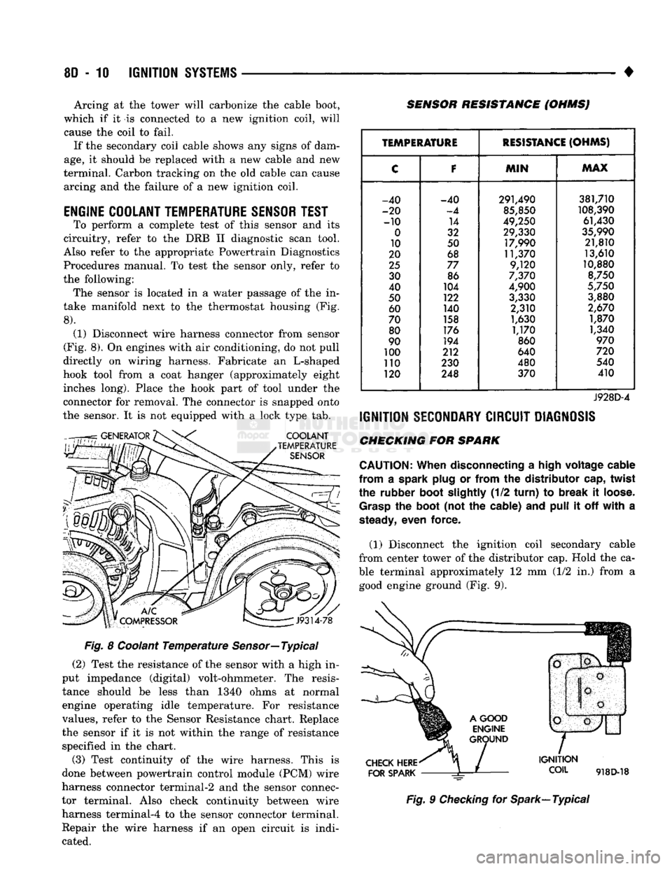
the following: The sensor is located in a water passage of the in
take manifold next to the thermostat housing (Fig.
8).
(1) Disconnect wire harness connector from sensor
(Fig. 8). On engines with air conditioning, do not pull
directly on wiring harness. Fabricate an L-shaped
hook tool from a coat hanger (approximately eight inches long). Place the hook part of tool under the
connector for removal. The connector is snapped onto
the sensor. It is not equipped with a lock type tab.
COOLANT
TEMPERATURE
SENSOR
SENSOR RESISTANCE (OHMSJ
V
J9314-78
Fig. 8 Coolant Temperature Sensor—Typical (2) Test the resistance of the sensor with a high in
put impedance (digital) volt-ohmmeter. The resis tance should be less than 1340 ohms at normal
engine operating idle temperature. For resistance
values, refer to the Sensor Resistance chart. Replace
the sensor if it is not within the range of resistance specified in the chart.
(3) Test continuity of the wire harness. This is
done between powertrain control module (PCM) wire
harness connector terminal-2 and the sensor connec
tor terminal. Also check continuity between wire harness terminal-4 to the sensor connector terminal. Repair the wire harness if an open circuit is indi
cated.
TEMPERATURE
RESISTANCE
(OHMS)
C
F
MIN
MAX
-40 -40 291,490 381,710
-20
-4
85,850
108,390
-10 14
49,250 61,430
0
32 29,330
35,990
10 50 17,990 21,810
20 68 11,370 13,610
25
77 9,120 10,880
30 86
7,370
8,750
40 104
4,900
5,750
50 122
3,330 3,880
60 140 2,310
2,670
70 158
1,630 1,870
80 176
1,170 1,340
90 194
860
970
100 212 640
720
110 230 480 540
120 248 370 410
J928D-4
IGNITION
SECONDARY
CIRCUIT
DIAGNOSIS
CHECKING FOR SPARK
CAUTION:
When
disconnecting a
high
voltage
cable
from
a spark
plug
or
from
the
distributor
cap,
twist
the rubber
boot
slightly
(1/2
turn)
to
break
it
loose.
Grasp
the
boot
(not the cable) and
pull
it off
with
a
steady,
even force.
(1) Disconnect the ignition coil secondary cable
from center tower of the distributor cap. Hold the ca
ble terminal approximately 12 mm (1/2 in.) from a good engine ground (Fig. 9).
CHECK
HERE
FOR
SPARK
IGNITION
COIL
918D-18
Fig. 9 Checking for Spark—Typical
Page 367 of 1502
8D
- 16
IGNITION
SYSTEMS
• other operating conditions are causing engine over
heating. (The heat range rating refers to the operat
ing temperature of a particular type spark plug.
Spark plugs are designed to operate within specific
temperature ranges. This depends upon the thickness and length of the center electrodes porcelain insula
tor.)
GROUND
ELECTRODE
CENTER
ELECTRODE
DISSOLVED
J908D-14 Fig. 26 Preignition Damage
SPARK
PLUG
OVERHEATING
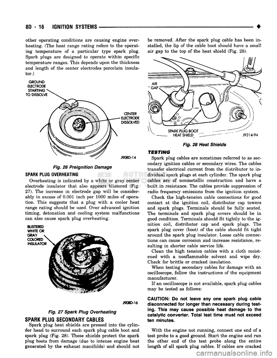
Overheating is indicated by a white or gray center
electrode insulator that also appears blistered (Fig.
27).
The increase in electrode gap will be consider
ably in excess of 0.001 inch per 1000 miles of opera
tion. This suggests that a plug with a cooler heat
range rating should be used. Over advanced ignition
timing, detonation and cooling system malfunctions can also cause spark plug overheating.
BLISTERED
WHITE
OR
J908D-16
Fig. 27 Spark Plug Overheating
SPARK
PLUG
SECONDARY
CABLES
Spark plug heat shields are pressed into the cylin
der head to surround each spark plug cable boot and spark plug (Fig. 28). These shields protect the spark
plug boots from damage (due to intense engine heat
generated by the exhaust manifolds) and should not be removed. After the spark plug cable has been in
stalled, the lip of the cable boot should have a small
air gap to the top of the heat shield (Fig. 28).
Fig.
28 Heat
Shields
TESTING
Spark plug cables are sometimes referred to as sec
ondary ignition cables or secondary wires. The cables
transfer electrical current from the distributor to in dividual spark plugs at each cylinder. The spark plug
cables are of nonmetallic construction and have a
built in resistance. The cables provide suppression of radio frequency emissions from the ignition system.
Check the high-tension cable connections for good
contact at the ignition coil, distributor cap towers and spark plugs. Terminals should be fully seated.
The terminals and spark plug covers should be in good condition. Terminals should fit tightly to the ig
nition coil, distributor cap and spark plugs. The spark plug cover (boot) of the cable should fit tight
around the spark plug insulator. Loose cable connec
tions can cause corrosion and increase resistance, re sulting in shorter cable service life. Clean the high tension cables with a cloth moist
ened with a nonflammable solvent and wipe dry.
Check for brittle or cracked insulation. When testing secondary cables for damage with an
oscilloscope, follow the instructions of the equipment
manufacturer. If an oscilloscope is not available, spark plug cables
may be tested as follows:
CAUTION:
Do not leave any one
spark
plug
cable
disconnected
for
longer
than
necessary
during test
ing.
This
may
cause
possible
heat
damage
to the
catalytic converter. Total test
time
must
not exceed
ten
minutes.
With the engine not running, connect one end of a
test probe to a good ground. Start the engine and run the other end of the test probe along the entire length of all spark plug cables. If cables are cracked